Ebmpapst CN1083 Manual

Operating and Maintenance Instructions
210-OMI12422_Iss3.doc ORIGINAL INSTRUCTIONS Page 1 of 9
ebm-papst UK Ltd, 2012
Chelmsford Business Park Chelmsford Essex CM2 5EZ
Telephone: +44(0)1245468555 Fax: +44(0)1245466336
e-mail [email protected]bmpapst.com
CN1083
Table of Contents
Introduction .............................................................................................................................................................. 2
Specification ............................................................................................................................................................ 2
Connection Details (see “Terminal Block Use” below”) ........................................................................................... 2
Fan Compatibility ..................................................................................................................................................... 3
Mechanical Outline .................................................................................................................................................. 3
Safety ...................................................................................................................................................................... 3
EMC Compliance..................................................................................................................................................... 3
ESD ......................................................................................................................................................................... 4
Installation ............................................................................................................................................................... 4
Operation ................................................................................................................................................................. 6
Fan Speed Control: ............................................................................................................................................. 6
Anti–Frost Supply Fan Shut-Off .......................................................................................................................... 6
Summer Bypass Relay: ....................................................................................................................................... 6
Filter Maintenance Alarm .................................................................................................................................... 6
Fan Monitor: ........................................................................................................................................................ 6
Alarm Relay:........................................................................................................................................................ 6
Power-up Check.................................................................................................................................................. 6
Maintenance and Servicing ..................................................................................................................................... 6
Terminal Block Use ................................................................................................................................................. 7
PCB Component Location ....................................................................................................................................... 8
Declaration of Conformity ........................................................................................................................................ 9
The most recent version of this document may be downloaded at: www.ebmpapst.co.uk/instructions
Part No
CN108
3
Description
Commercial H U
(Heat ecovery Unit)
Controller
Issue
Date
Bug no
Comments
1
19 July 2012
1206
Add CE front sheet
2
31
Jan 2013
1206
Clarify instructions
3
6
Apr
2013
1
9
15
Rotary Switches
S
2
&
S3 operation
&
Supply
Current

Operating and Maintenance Instructions
210-OMI12422_Iss3.doc ORIGINAL INSTRUCTIONS Page 2 of 9
ebm-papst UK Ltd, 2012
Chelmsford Business Park Chelmsford Essex CM2 5EZ
Telephone: +44(0)1245468555 Fax: +44(0)1245466336
e-mail [email protected]bmpapst.com
CN1083
Introduction
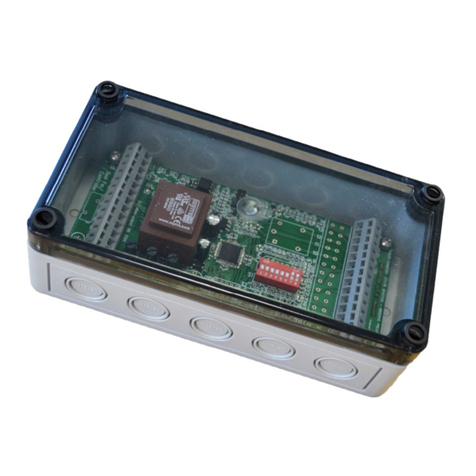
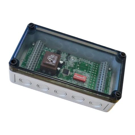
Commercial HRU (Heat Recovery Unit) Controller, mains powered with enclosure, controls two fans selecting
Stop/Run and Low/High speed. Speeds preset by on-board trimmers, independent Low and High speed setting
for each fan. Selection of Stop/Run and Low/High speed by switched 230VAC and volt-free inputs. With
indicators and alarm outputs. Configurable options set by on-board DIP switches. Timer based Filter Maintenance
Alarm. Summer Bypass Relay for damper control and Anti-Frost shut off, temperature sensors SN1060 included.
Specification
CN
108
3
Supply Voltage
207
–
253 V
AC
AC line Frequency
47
–
63 Hz
Supply C
urrent
Controller
1
5
mA
, plus Fan
s
if wired via PCB 13A max.
Alarm and Filter elay
Contact
rating
, 1
00mA
max,
60VDC max
Summer Bypass elay
Contact rating
, 5A max, 230VAC
or 24VDC
max.
Temperature Sensors
SN1060 thermistor sensor assemblies, 2m lead
length
Operating Environment
-
30 to 60
°C
, IP66 Enclosure
Connection Details (see “Terminal Block Use” below”)
Mains Connector J1
Pin
Function
SL1
1
Switched Live 1,
Low/High fan speed
Select
i
nput
SL2
2
Switched Live 2,
Stop/Run control i
nput (shipp
ed with link to 230VAC Live to
Run
)
L
3
230VAC, Live (for
Stop/Run control
link)
L
4
230VAC, Live (
Supply
to Fan)
L
5
230VAC, Live (Input)
L
6
230VAC, Live (
Supply
to Fan)
N
7
230VAC, Neutral (spare)
N
8
230VAC, Neutral (
Supply
to Fan)
N
9
230VAC, N
eutral (Input)
N
10
230VAC, Neutral (
Supply
to Fan)
E
11
Earth (
Supply
to Fan)
E
12
Earth (Input)
E
13
Earth (Supply to Fan)
E
14
Earth (spare)
Control Connector One, J2
Pin
Function
1
Alarm Relay, Contact A
(Contacts Closed = No Alarm)
2
Alarm Re
lay, Contact B
3
Fan 1 Speed Control PWM
Output
Supply
Fan
4
Fan 1 Tachometer Open Collector / Relay Input
5
Fan 1 GND / 0V
6
Fan 2 Speed Control PWM
Output
Extract
Fan
7
Fan 2 Tachometer Open Collector / Rela
y Input
8
Fan 2 GND / 0V
9
BMS Lo
w/High fan speed
Select Input, Volt Free Contacts
10
0V for BMS
11
Stop/Run control i
nput, Volt Free Contacts (shipped with link to 0V to
Run
)
12
0V for Stop/Run
13
Remote Low/High fan speed
Select Input, Volt Free Contacts
14
0V for Remote Low/High
Note: all “0V” terminals on J2 & J3 are commoned.

Operating and Maintenance Instructions
210-OMI12422_Iss3.doc ORIGINAL INSTRUCTIONS Page 3 of 9
ebm-papst UK Ltd, 2012
Chelmsford Business Park Chelmsford Essex CM2 5EZ
Telephone: +44(0)1245468555 Fax: +44(0)1245466336
e-mail [email protected]bmpapst.com
CN1083
Control Connector Two, J3
Pin
Function
1
Filter Maintenance Relay, Contact A
2
Filter Maintenance Relay, Contact B
3
Thermistor 1
,
SN1060
,
first wire
.
Anti
-
Frost
Temperature
Sensor
4
Thermistor 1
,
SN106
0,
second wire
.
5
T
hermistor 2
,
SN1060
,
first wire
.
Summer Bypass
Temperature
Sensor
6
0V
(normally unused)
7
Low/High fan speed
Select Input 3, Volt Free Contacts
8
0V for Low/High fan speed
Select Input 3
9
24V
DC
Unregulated
Output, 25mA max.
10
S
ummer Bypass Relay, Normally Open Contact
11
Summer Bypass Relay, Common Contact
12
Summer Bypass Relay, Normally Closed Contact
13
Thermistor
2,
SN1060,
second wire
.
14
reserved
Fan Compatibility
Fan Speed control outputs compatible with EC 0-10V or Open Collector PWM speed controlled fans, 2kHz PWM,
maximum of 12 EC Fans per 0-10V output.
Tachometer / Relay input compatible with Open Collector tachometer or Relay Alarm fans.
Mechanical Outline
Enclosure 180(L) x 94(W) x 57(H), transparent lid for LED visibility, fixing centres 165 x 79mm
PCB 157mm x 71mm, Hole centres 146 x 60mm. Height 31mm max.
LED Identification LED “Fan1” and “Fan2” Run and Alarm, indicated by PCB silk screen legend
LED “En” Run Enable and LED “B” Fast, indicated by PCB silk screen legend
LED “FILTER” – filter maintenance LED, indicated by PCB silk screen legend
Trimmer Identification Trimmer indicated by PCB silk screen legend, R1, R2, R3 and R4
IP Rating IP66 with Enclosure.
Cable Glands Not included. Enclosure supplied, has “knock-outs” to suit 16mm or 20mm glands.
Safety
•Installation must be by qualified personnel in accordance with local applicable standards.
•This equipment must be Earthed.
•Access is limited to service personnel only. Live parts accessible when cover removed.
•Residual risk of contact with fan. Maintenance personnel should take due care and attention.
•Complies with Low Voltage Directive 37/23/EEC as amended by 93/68/EEC
•Complies with EN60335-1 - Specification for safety of household and similar electrical appliances
•Connector J1 Terminals SL1 and SL2, and Summer Bypass relay contacts may be live even with the
controller supply disconnected
•EC Fans use Capacitors to store mains voltage. Contact with the mains wiring must be avoided for 5
minutes following supply disconnection.
•If the Summer Bypass relay is used to switch mains voltage then the controller 0V should be connected to
Protective Earth and the supply should incorporate a residual-current circuit breaker.
EMC Compliance
BS EN61000-6-3:2007 (emissions), BS EN61000-6-2:2005 (immunity)
Radiated Emissions BS EN55022:2006, Class B, Radiated Immunity EN61000-4-3:2002 +A1+A2
Fast Transient Bursts EN61000-4-4:2004, Conducted Immunity EN61000-4-6:2007

Operating and Maintenance Instructions
210-OMI12422_Iss3.doc ORIGINAL INSTRUCTIONS Page 4 of 9
ebm-papst UK Ltd, 2012
Chelmsford Business Park Chelmsford Essex CM2 5EZ
Telephone: +44(0)1245468555 Fax: +44(0)1245466336
e-mail [email protected]bmpapst.com
CN1083
ESD
Many modern electronic components are susceptible to damage from Electro Static Discharge (Static Electricity).
During commissioning, avoid unnecessary contact with electronic components on PCB’s.
PCB’s which are Static Sensitive should be stored in anti-static packaging until installed.
Installation
General:
See “Safety” information above.
For connections, see Connection Details table above. Route control wiring separately from AC mains wiring.
Remove enclosure knock-outs as required to fit cable glands, taking care not to damage the PCB. Cable entry at
enclosure end is recommended.
Tools:
A 2.5mm flat screwdriver is recommended for the screw terminal block clamps and Variable Resistor adjustment.
A voltmeter is required during commissioning.
230VAC Supply:
Controller connection to 230VAC supply must be fused to 13A maximum.
The supply for single phase fans up to 13A total load may be connected via this control PCB, connect Fans to
230VAC output and Earth output terminals. For higher currents or 3-phase fans route supply direct to fans.
Fans:
Connect fan supply, speed control and tachometer leads, see table above for connections. If fan has a 10V
output wire cut back & insulate. If fans are Alarm Relay type (not Tachometer), connect fan relay between 0V and
tachometer Input. If fan monitoring is not required, then link tachometer Input to 0V to prevent alarms.
Temperature sensors:
Connect the two Thermistor cable assemblies SN1060 as shown in the table above. Normally both sensors
should be installed in the supply airflow input to the HRU.
Select Inputs:
Connect Run/Stop and Speed/Set-point select inputs as required for the application, see Tables below.
PCB Switches and Variable esistors:
Set DIP Switches and Variable Resistors as required, see tables and procedures below.
Potentiometers
RV1
Supp
ly Fan PWM Output Low Speed
, 20% to 100%
RV2
Supply Fan PWM Output High Speed
, 20% to 100%
RV3
Extract Fan PWM Output Low Speed
, 20% to 100%
RV4
Extract Fan PWM Output High Speed
, 20% to 100%
DIP Switch 1
Position
OFF
ON
1,
2
, 3
Maintenance Timer,
se
e table below
4
No High Speed
Start
Delay
.
High Speed
Start Delay, Three minute fixed timer.
5
No High Speed
Run
-
on.
High Speed
Run
-
on O
ff/ON, 20 minute fixed timer
6
RESERVED, MUST BE [Off]
7
Supply Fan
PWM, Open Collector
Supply Fan
PWM, 0
-
10V
8
Ext
ract
Fan PWM, Open Collector
Extract
Fan PWM, 0
-
10V

Operating and Maintenance Instructions
210-OMI12422_Iss3.doc ORIGINAL INSTRUCTIONS Page 5 of 9
ebm-papst UK Ltd, 2012
Chelmsford Business Park Chelmsford Essex CM2 5EZ
Telephone: +44(0)1245468555 Fax: +44(0)1245466336
e-mail [email protected]bmpapst.com
CN1083
DIP Switch Position
Filter Maintenance Timer
1
2
3
Off
Off
Off
Timer
Unused (no alarm)
Off
ON
Off
3 month
Off
Off
ON
6 month
Off
ON
ON
12 month
ON
-
-
Reset
DIP Switch 2, otary
Position
Anti
–
Frost
Supply Fan
Shut-Off Temperature °C
0
RESERVED
1
-
6
2
-
5
3
-
4
4
-
3
5
-
2
6
-
1
7
0
8
1
9
2
A
3
B
4
C
5
D
6
E
7
F
8
DIP Switch 3, otary
Position
Summe
r Bypass elay
Operate Temperature °C
0
RESERVED
1
1
6
2
1
7
3
1
8
4
1
9
5
20
6
21
7
2
2
8
2
3
9
2
4
A
2
5
B
2
6
C
2
7
D
2
8
E
2
9
F
30

Operating and Maintenance Instructions
210-OMI12422_Iss3.doc ORIGINAL INSTRUCTIONS Page 6 of 9
ebm-papst UK Ltd, 2012
Chelmsford Business Park Chelmsford Essex CM2 5EZ
Telephone: +44(0)1245468555 Fax: +44(0)1245466336
e-mail [email protected]bmpapst.com
CN1083
Operation
Fan Speed Control:
1) un Enable: Fans will not run unless both run enable signals (Switched Live and Volt Free) are active.
LED “En” will be illuminated if Run enabled, LED will flash mostly off if not. Unit is shipped with both
enables linked.
2) Low / High Speed: Fans will run at High speed if any High Speed signal (Switched Live or Volt Free) is
active, LED “B” illuminated. If the “High” potentiometer set speed is lower than the “Low” potentiometer
set speed the fan will continue at the “Low” set speed.
3) High Speed Delay Start: Enabled by DIP Switch. PWM Outputs will remain at “Low” speed after the
“High Speed” input becomes active, for the Delay Start timer period, 3 minutes. (exception - BMS input
responds immediately) If High Speed Delay timer is running LED “B” will flash, mostly Off.
4) Run-on: Enabled by DIP Switch. PWM Outputs will remain at “High” speed after the “High Speed” input
ceases to be active, for the run-on timer period, 20 minutes. (exception - BMS input responds
immediately) If run-on timer is running LED “B” will flash, mostly On.
Anti–Frost Supply Fan Shut-Off
The Supply Air Temperature is monitored by Thermistor 1. While the temperature is below that set by the Rotary
DIP Switch S2 the supply fan will shut off. Hysteresis is fixed, two degrees centigrade.
Summer Bypass Relay:
The Supply air temperature is monitored by Thermistor 2. While the temperature is above that set by Rotary DIP
Switch S3 the relay will switch over. Hysteresis is fixed, two degrees centigrade.
Filter Maintenance Alarm
The Filter Maintenance Alarm is generated by a timer.
The controller times the fan hours run, while the timer is running the Maintenance Relay contacts will be closed
and the Maintenance LED will not be illuminated. The timer will pause if fan run is not enabled.
When the timer reaches the Filter Maintenance Alarm Period set the Filter Maintenance Relay contacts will open
and the Filter LED will illuminate red.
The alarm will persist until reset by DIP switch setting. During Reset the HRU LED’s will flash. Return the switch
to the non-reset position for normal timer running.
The controller stores the hours run count in non-volatile memory so that the count continues following power
cycle.
Fan Monitor:
“FAN1” and “FAN2” LEDS, Green LED = Fan Running at 20% speed or above, Red LED = Fan Alarm
Alarm Relay:
Alarm Relay output: Contacts closed = No Alarm, Contacts Open = Fan Alarm or Thermistor Alarm or Power Fail.
Power-up Check
At power-up all LED’s will illuminate and Relays energise for a few seconds. The fan run will be checked unless
“Fan Stop” is selected.
Maintenance and Servicing
The PCB has no replaceable parts, if a fault develops return the PCB to the manufacturer.

Operating and Maintenance Instructions
210-OMI12422_Iss3.doc ORIGINAL INSTRUCTIONS Page 7 of 9
ebm-papst UK Ltd, 2012
Chelmsford Business Park Chelmsford Essex CM2 5EZ
Telephone: +44(0)1245468555 Fax: +44(0)1245466336
e-mail [email protected]bmpapst.com
CN1083
Terminal Block Use
The terminal blocks fitted are operated as follows:
Insert a 2.5mm or 3mm flat blade screwdriver fully into the upper hole as shown, to open the terminal wire entry.
Insert the wire into the lower hole, then remove the screwdriver to leave the wire clamped in the terminal.
Alternatively, open the wire entry by inserting the screwdriver fully from the opposite side of the connector as
shown
Insert the wire into the lower hole, then remove the screwdriver to leave the wire clamped in the terminal.
Check wire clamp has moved clear to
allow wire entry

Operating and Maintenance Instructions
210-OMI12422_Iss3.doc ORIGINAL INSTRUCTIONS Page 8 of 9
ebm-papst UK Ltd, 2012
Chelmsford Business Park Chelmsford Essex CM2 5EZ
Telephone: +44(0)1245468555 Fax: +44(0)1245466336
e-mail [email protected]bmpapst.com
CN1083
PCB Component Location
Key PCB components are shown below
J1 Pin1 High Speed un Enabled Filter S1 S2 S3
LED “B” LED “En” LED
Live Circuit SELV Circuit
Live Circuit
1 3 Fan1 un Fan2 un NTC1 Alarm J3 Pin1
2 4 LED LED LED
Fan1 Alarm Fan2 Alarm NTC2 Alarm J2 Pin1
LED LED LED
otary DIP Switch position numbering

Operating and Maintenance Instructions
210-OMI12422_Iss3.doc ORIGINAL INSTRUCTIONS Page 9 of 9
ebm-papst UK Ltd, 2012
Chelmsford Business Park Chelmsford Essex CM2 5EZ
Telephone: +44(0)1245468555 Fax: +44(0)1245466336
e-mail [email protected]bmpapst.com
CN1083
Declaration of Conformity
06/04/2016 11:43:43
Table of contents
Other Ebmpapst Controllers manuals