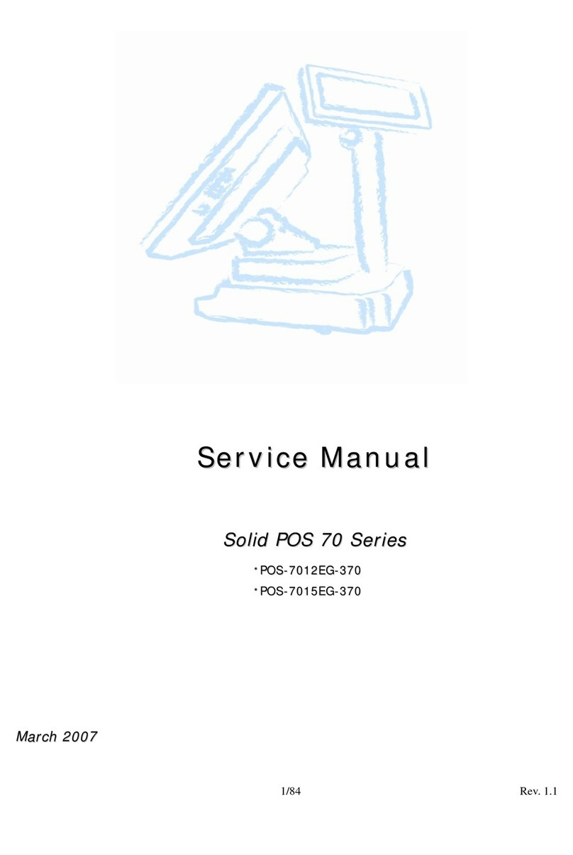
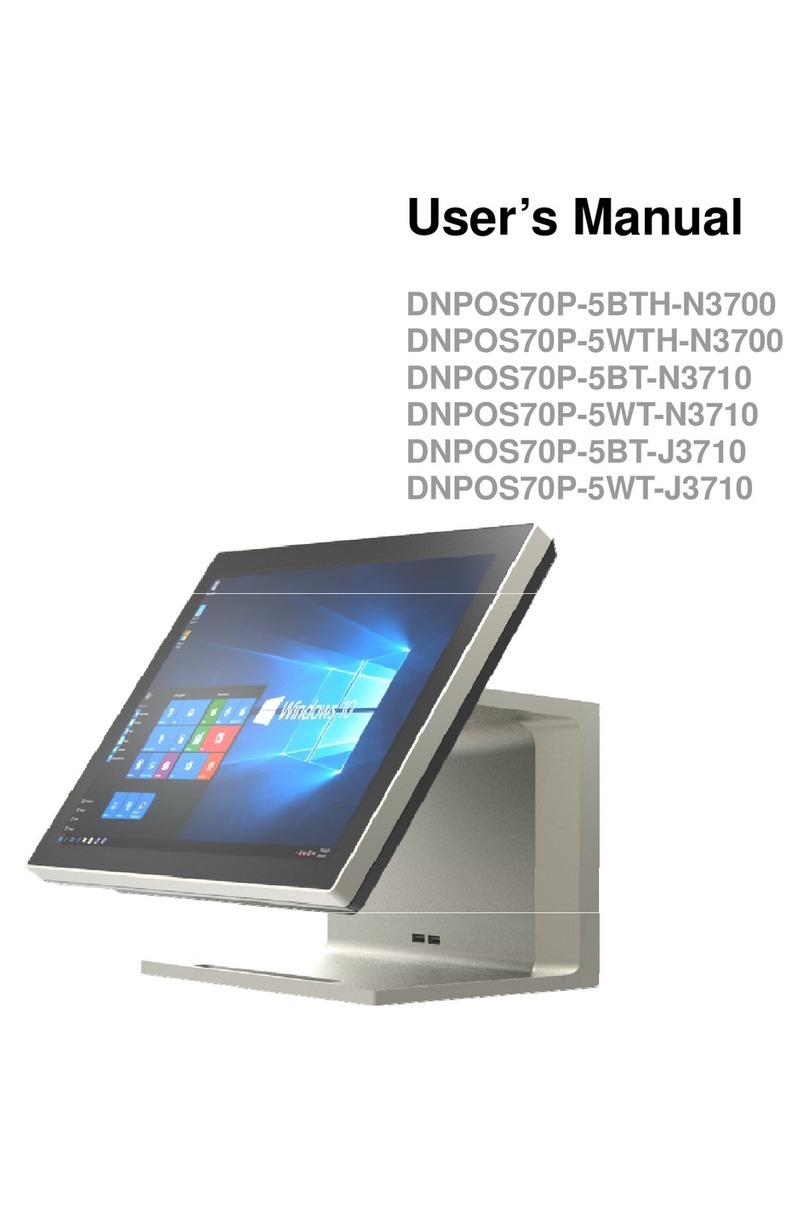
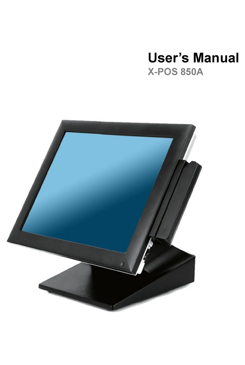
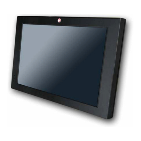
EBN POS-7012EG-370 User manual

EBN Technology Corp.
3/20/2007 1/84 Rev. 1.1
S
Se
er
rv
vi
ic
ce
e
M
Ma
an
nu
ua
al
l
S
So
ol
li
id
d
P
PO
OS
S
7
70
0
S
Se
er
ri
ie
es
s
*
*P
PO
OS
S-
-7
70
01
12
2E
EG
G-
-3
37
70
0
*
*P
PO
OS
S-
-7
70
01
15
5E
EG
G-
-3
37
70
0
M
Ma
ar
rc
ch
h
2
20
00
07
7
©Copyright 2007 by EBN Techno ogy Corp. A Rights Reserved.

EBN Technology Corp.
3/20/2007 2/84 Rev. 1.1
Contents
1 Chapter 1 : Troubleshooting ........................................................................................................... 4
1.1 Symptoms and Solutions .......................................................................................................... 4
1.2 BIOS Upgrade ......................................................................................................................... 7
2 Chapter 2 : Disassembly , Assembly............................................................................................... 9
2.1 Main Unit ................................................................................................................................ 9
2.1.1 Front Bezel + Sponge Bezel .................................................................................... 9
2.1.2 Touch Panel + Touch Screen Holder...................................................................... 10
2.1.3 LCD, AUO 15” 1024 x 768 ................................................................................... 12
2.1.4 MSR (Refer to 2.5.4)............................................................................................. 13
2.1.5 Mother Board (Refer to 2.3) .................................................................................. 13
2.1.6 EMI Chassis.......................................................................................................... 14
2.1.7 Key Lock Set ........................................................................................................ 15
2.2 Base Unit............................................................................................................................... 18
2.2.1 Base Housing ........................................................................................................ 18
2.2.2 Swivel Housing Rear / Front ................................................................................. 21
2.2.3 P/S 220W W/PFC.................................................................................................. 22
2.2.4 I/O Board .............................................................................................................. 25
2.2.5 Jumper Cover........................................................................................................ 27
2.3 Boards ................................................................................................................................... 28
2.3.1 Main Board ........................................................................................................... 28
2.3.2 Bridge Board......................................................................................................... 30
2.3.3 Inverter ................................................................................................................. 31
2.3.4 Touch Control Board............................................................................................. 32
2.3.5 Button Board (For POS 75) ................................................................................... 33
2.4 Cables ................................................................................................................................... 34
2.4.1 Cable, M/B To Inverter.......................................................................................... 34
2.4.2 Cable, M/B To Touch Control BD ......................................................................... 35
2.4.3 Cable, M/B To Speaker ......................................................................................... 37
2.4.4 Cable, M/B To I/O BD 100P ................................................................................. 38
2.4.5 Cable, M/B To HDD 80P....................................................................................... 39
2.4.6 Cable, 2nd VGA to I/O Board................................................................................ 39
2.4.7 Cable, M/B To I/O BD 20P USB ........................................................................... 41
2.4.8 Cable, M/B To Button Board................................................................................. 41
2.4.9 Cable, LCD to Bridge Board ................................................................................. 42
2.5 Main & Base Unit assembly .................................................................................................. 44
2.6 Accessories............................................................................................................................ 47
EBN Technology Corp.
3/20/2007 3/84 Rev. 1.1
2.6.1 HDD ..................................................................................................................... 47
2.6.2 Pole Display.......................................................................................................... 48
2.6.3 MSR ..................................................................................................................... 51
2.6.4 MSR+ I Button...................................................................................................... 53
2.6.5 MSR+ Smart Card................................................................................................. 55
2.6.6 2nd Display W/ Touch........................................................................................... 59
2.6.7 RFID..................................................................................................................... 65
2.6.8 Compact Flash ...................................................................................................... 67
2.6.9 Smart Card ............................................................................................................ 69
2.6.10 I Button................................................................................................................. 71
2.6.11 Mini PCI Wireless LAN ........................................................................................ 73
3 Chapter 3 : Spare parts list............................................................................................................ 76
3.1 Main Unit .............................................................................................................................. 76
3.1.1 Explode of Main Unit............................................................................................ 76
3.1.2 Main Unit Parts list & quotation............................................................................ 76
3.2 Base Unit............................................................................................................................... 78
3.2.1 Explode of Base Unit ............................................................................................ 78
3.2.2 Base Unit Parts list & quotation............................................................................. 79
3.3 Cables ................................................................................................................................... 79
3.4 Accessories............................................................................................................................ 81
3.4.1 Power Cord ........................................................................................................... 81
3.4.2 HDD ..................................................................................................................... 81
3.4.3 Pole Display.......................................................................................................... 81
3.4.4 MSR ..................................................................................................................... 82
3.4.5 2nd Display........................................................................................................... 82
3.4.6 OS......................................................................................................................... 83
3.4.7 RFID..................................................................................................................... 83
3.4.8 Compact Flash ...................................................................................................... 83
3.4.9 Memory ................................................................................................................ 83
3.4.10 Smart Card +MSR 3T RS232 ................................................................................ 83
3.4.11 I Button +MSR 2T KB .......................................................................................... 84
3.4.12 Wireless LAN ....................................................................................................... 84

EBN Technology Corp.
3/20/2007 4/84 Rev. 1.1
1Chapter 1 : Troubleshooting
1.1 Symptoms and Solutions
Error Code
Symptom Check Points Detail Steps
1001 NO BOOT with
Power On
1.RAM
2.CPU
3.MB(2.3.1)
1. Check LED Light (Upper Left) should be on
2. If yes to item 1, open upper case, check if RAM well plugged
on the memory slot
3. Check golden finger cleanness, if
not clean, use pencil eraser
to clean golden finger
4. If still fail, replace with another RAM for testing
5. If fail, replace with another CPU for testing
6. If fail, replace with another mother board for testing
7. If fail, RMA system to EBN
1002 NO POWER
1. Power cord
2. Power button
board (2.3.5)
3. Power button
cable(2.3.7.8)
4. MB (2.3.1)
5.Power
Supply(2.2.3)
1. Check Power Cord is well plugged or not
2. If yes to item 1, open upper case, check if power button
damaged, if yes, replace with another power button board (POS
75) or replace with another MB(POS 72)
3. If power button not damaged, check if power button cable to
MB well plugged.
4. If fail, replace with another power button cable
5. If fail, replace with another MB(POS 75) for testing
6. If fail, replace with another power supply for testing
7. If fail, System RMA to EBN
1003 System HANG
Up
1.RAM
2.CPU
3.MB(2.3.1)
1
. Check golden finger cleanness, if not clean, use pencil eraser
to clean golden finger
2. If still fail, replace with another RAM for testing
3. If fail, replace with another CPU for testing
4. If fail, replace with another mother board for testing
5. If fail, System RMA to EBN
1004 LCD Blank
1.Bridge Board to
LCD Cable(2.3.7.9)
2.Bridge Board
(2.3.2)
3.MB(2.3.1)
1. Shut Down Power
2. Open upper case, check cable between bridge board and LCD
well connected or not. Replace with another LCD cable for
testing
3. If fail, replace with another bridge board
4. If fail, replace with another mother board
5. If fail, System RMA to EBN

EBN Technology Corp.
3/20/2007 5/84 Rev. 1.1
Error Code
Symptom Check Points Detail Steps
1005 LCD Turn
Black
1. Inverter to LCD
cable,
2. Inverter to MB
cable, (2.3.7.1)
3. Inverter board
4. MB(2.3.1)
5. LCD(2.1.3)
1. Shut down power
2. Open upper case, check cable between inverter and LCD we
ll
connected or not.
4. If fail, check cable between inverter and mother board well
connected or not. Replace with another inverter and MB cable
for testing
5. If fail, replace with another inverter board for testing
6. If fail, replace with another mother board for testing
7. If fail, System RMA to EBN
1006 HDD Unstable
1. HDD (2.5.2)
2. HDD Cable
(2.3.7.5)
3. MB(2.3.1)
1. Shut down power
2. Open HDD Cover, check HDD 80pin cable and HDD power
cable well connected or not
3. If fail, replace with another HDD for testing
4. If fail, open upper case, check cable between HDD and
Mother board well connected or not
5. If fail, replace with another mother board for testing
6. If fail, system RMA to EBN
1007
Error
Message:
CMOS
checksum error
1. On Board
Battery(2.3.6)
2. MB(2.3.1)
1. Shut down power
2. Open upper case, check on board battery well connected /
damage or not
3. If fail, replace with another battery
4. If fail, replace with another mother board
5. If fail, system RMA to EBN
1008 Touch Fail
1. Driver (NA)
2. Control board to
MB cable (2.3.7.2)
3.Touch control
board(2.3.4)
4.MB(2.3.1)
5.Touch panel(2.1.2)
1. Reinstall touch driver, working mode select "PnP"
2. If fail, shut down power
3. Open upper case, check if cable between touch panel and
touch control board well connected.(Replace the cable with
touch panel at item 10)
4. If fail, check if cable between touch control board and MB
well
connected. Replace with another touch control board to MB
cable
5. Check if switch (# 3) on touch control board at "On" position
6. If fail, check M/B JP10 jumper setting to 2-3
7. If fail, replace with another touch control board
8. If fail, replace with another M/B for testing
9. Replace with another touch panel for testing
10. RMA system to EBN

EBN Technology Corp.
3/20/2007 6/84 Rev. 1.1
Error Code
Symptom Check Points Detail Steps
1009 Boot Up K/B
Malfunction
1.100PIN Cable
2.MB(2.3.1)
1. Shut down power
2. Check keyboard cable connection
3. If fail, replace with another keyboard for testing
4. If fail, open upper case, check 100 pin cable betwee
n IO board
and MB well connected or not
5. If fail, replace with another MB for testing
6. If fail, system RMA to EBN
1010 PS/2 Mouse
Fail
1.100PIN Cable
2.MB(2.3.1)
1. Shut down power
2. Check mouse cable connection
3. If fail, replace with another mouse
4. If fail, open upper case, check 100 pin cable between IO board
and MB well connected or not
5. Replace with another MB for testing
6. If fail, system RMA to EBN
1011 MSR Fail
1. MSR to MB
Cable(2.5.4)
2. MB(2.3.1)
1. Shut down power
2. Open upper case, check if MSR cable goes underneath
inverter and well connected to MB location (CN12). Note: the
cable must go through EMI chassis breach
3. If fail, replace with another MSR
4. If fail, RMA MSR to EBN
1012 COM Port Fail
1. Jumper setting
2. 100PIN cable
3. MB(2.3.1)
1. Shut down power
2. Move to Bottom side, open jumper setting cover, check if
jumper setting same with default setting chart. Note: If device
connector is with voltage, jumper setting needs to change to 5V
or 12V based on different device definition
3. If fail, open upper case, check 100pin cable to MB well
connected or not
4. If fail, replace with another MB for testing
5. If fail, RMA system to EBN
1013 USB Fail
1. Device Check
2. USB cable
3. MB(2.3.1)
1. Shut down power
2. Check device cable to USB port well connected or not
3. If fail, replace with another device
4. If fail, open upper case, check USB Cable to MB location
(CN11) well connected or not
5. If fail, replace with another MB for testing
6. If fail, RMA system to EBN

EBN Technology Corp.
3/20/2007 7/84 Rev. 1.1
1.2 BIOS Upgrade
1. Boot the system with a bootable floppy disk
a. A Windows 98/ME startup disk can be used
b.Or you can create an MS-DOS startup disk under Windows XP, to create an MS-DOS startup disk
under
Windows XP, right click on the 3 ½ floppy drive icon under my computer and select format. On the
format
dialog box, check the box next to “Create MS-DOS startup disk” and then click the start button to make
a
MS-DOS startup disk..
2. Once you boot off of the bootable floppy disk, replace the bootable floppy disk with the floppy disk
containing
the bios files.
3. To update the BIOS using the example above you would type the following command.
a. A:\F82744 s171r21.rom, then push the enter key.
b. Follow the onscreen prompts to update the BIOS.
4. DO NOT TURN OFF THE POWER or RESET/REBOOT the SYSTEM before the BIOS update is
completed, stopping the BIOS UPATE before it is completed will cause the system to become
non-functional.
F82744.exe = BIOS FLASH UTILITY

EBN Technology Corp.
3/20/2007 8/84 Rev. 1.1
5. Reboot the system once the bios update has been completed.
Note:
The BIOS contained here are exclusively for EBN POS72/75 only. EBN assumes no responsibility for any
damages resulting from improper use or lack of technical expertise.

EBN Technology Corp.
3/20/2007 9/84 Rev. 1.1
2Chapter 2 : Disassembly , Assembly
2.1 Main Unit
2.1.1 Front Bezel + Sponge Bezel
Item Photo Description
1
1. Use screw driver to open upper case.
2. 2 screws needs to be removed
2
1. Remove 2 screws
2. Remove cover bracket
3
1. Remove 2 screws from MSR cover
2. Remove 2 screws from inverter
3. Remove 3 cables from inverter
4
1. Remove 4 screws
1
2
3

EBN Technology Corp.
3/20/2007 10/84 Rev. 1.1
Item Photo Description
5
1. Separate front and back cover
6
1. Remove 12 screws
2. Remove speaker tape
7
1. Turn to front side
2. Remove and replace with another
front bezel
2.1.2 Touch Panel + Touch Screen Holder
Item Photo Description
1
1. Follow 2.1.1 item 1 to 7 turn to
Front side and remove front bezel
2. Remove 3 screws

EBN Technology Corp.
3/20/2007 11/84 Rev. 1.1
Item Photo Description
2
1. Turn to back side and remove tape
3
1. Turn to front side and remove touch
panel module
2. Replace with another touch panel
module

EBN Technology Corp.
3/20/2007 12/84 Rev. 1.1
2.1.3 LCD, AUO 15” 1024 x 768
Item Photo Description
1
1. Follow 2.1.2 item 1 to item 3 (action
1)
2. Turn to back side
3. Remove 4 screws
2
1. Cut plastic string
3
1. Remove 2 inverter cables
2. Remove LCD cable from LCD
chassis
3. Remove LCD chassis
4
1. Remove tape
2. Remove LCD cable
1
1
2
1
2

EBN Technology Corp.
3/20/2007 13/84 Rev. 1.1
Item Photo Description
5
1. Remove 2 screws from left LCD
holder
2. Remove 2 screws from right LCD
holder
3. Remove and replace with another
LCD
2.1.4 MSR (Refer to 2.5.4)
2.1.5 Mother Board (Refer to 2.3)

EBN Technology Corp.
3/20/2007 14/84 Rev. 1.1
2.1.6 EMI Chassis
Item Photo Description
1
1. Remove 2 screws
2
1. Open upper case
2. Remove 7 screws
3
1. Remove and replace another EMI
chassis

EBN Technology Corp.
3/20/2007 15/84 Rev. 1.1
2.1.7 Key Lock Set
Item Photo Description
1
1. Follow 2.1.6 item 1 to 3 remove
EMI chassis
2
1. Remove 2 screws
2. Remove cover bracket
3
1. Remove 2 antennas
2. Remove tape
4
1. Remove 4 screws

EBN Technology Corp.
3/20/2007 16/84 Rev. 1.1
Item Photo Description
5
1. Separate front cover from back cover
6
1. Remove 4 screws from hinge
7
1. Set upper case vertically
2. Remove back hinge cover
8
1. Set upper case horizontally
2. Remove front hinge cover
1
2
1
2

EBN Technology Corp.
3/20/2007 17/84 Rev. 1.1
Item Photo Description
9
1. Remove 3 screws at left hinge
2. Remove 3 screws at right hinge
10
1. Separate upper case from bottom
case
2. Pull out cables from upper case
11
1.Remove and replace with another key
lock set (W/ LCD Hinge Assembly /
LCD Base)

EBN Technology Corp.
3/20/2007 18/84 Rev. 1.1
2.2 Base Unit
2.2.1 Base Housing
Item Photo Description
1
1. Remove 4 screws from hinge front
side
2
1. Set upper case vertically
2. Remove back hinge cover
3
1.Set top upper case horizontally
2.Remove front hinge cover
4
1. Remove 3 screws at left hinge
2.Remove 3 screws at right hinge
1
2

EBN Technology Corp.
3/20/2007 19/84 Rev. 1.1
Item Photo Description
5
1.Separate upper case from bottom case
2.Pull out cables from upper case
6
1. Turn the bottom case to the bottom
side
2. Remove 2 screws to take off the kit
cover
7
1. Turn the bottom case top side
2. Take off kit cover
8
1. Turn the bottom case to the bottom
side
2. Remove 4 screws
3. Remove 4 Plastic foot

EBN Technology Corp.
3/20/2007 20/84 Rev. 1.1
Item Photo Description
9
1. Turn to the rear side of the bottom
case
2. Remove 2 screws to open the HDD
cover
10
1. Remove and replace with another
base housing from base chassis
This manual suits for next models
1
Table of contents
Other EBN Touch Terminal manuals

EBN
EBN X-POS956 User manual

EBN
EBN X-POS 850 User manual

EBN
EBN SPPC70-5B-C1G User manual

EBN
EBN POS60-8B-C1G User manual

EBN
EBN DNPOS70P-5BTH-N3700 User manual

EBN
EBN X-POS 850A User manual

EBN
EBN POS50A-5B-LX800 User manual

EBN
EBN Solid POS 70 Series User manual

EBN
EBN EZPPC70-2B-C1G User manual

EBN
EBN BPC65-B-A16G User manual