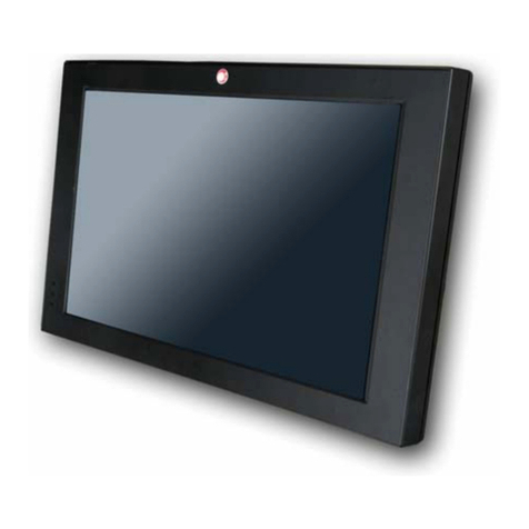
EBN X-POS956 User manual

User’s Manual
X-POS956


I
Copyrights
©2014 All rights reserved. The information in
this document is subject to change without
prior notice in order to improve reliability,
design and function and does not represent a
commitment on the part of the manufacturer.
This document contains proprietary
information protected by copyright. All
rights are reserved. No part of this
manual may be reproduced by any
mechanical, electronic, or other means in
any form without prior written permission
of the manufacturer.
All trademarks are property of their
respective owners
Liability Disclaimer
In no event will the manufacturer be liable
for direct, indirect, special, incidental, or
consequential damages arising out of the
use or inability to use the product or
documentation, even if advised of the
possibility of such damages.
Regulatory
Information
CE mark compliance
This device complies with EMC Directive
2004/108/EC issued by the Commission of
the European Community.
Warning: This a Class B product. In a
domestic environment this product
may cause radio interference, in which
case the user may be required to take
adequate measures
Safety Statement for Lithium
Battery

II
Contents
Copyrights...............................................................................................................I
Liability Disclaimer.................................................................................................I
Regulatory Information..........................................................................................I
CE mark compliance ....................................................................................I
Safety Statement for Lithium Battery..........................................................I
Contents.................................................................................................................II
1. Hardware Setup.................................................................................................1
1.1. Packing Contents..................................................................................1
1.2. Quick Tour.............................................................................................2
Front View and Rear View....................................................................2
Back Panel I/O.......................................................................................2
1.3. Basic Peripherals Installation..............................................................3
Power Adapter ......................................................................................3
Computer Mouse and Computer Keyboard........................................3
USB ODD...............................................................................................4
LAN Cable .............................................................................................4
Cash Drawer..........................................................................................4
Customer Display.................................................................................4
MSR........................................................................................................8
2nd Display ...........................................................................................9
1.4. Turn on the device..............................................................................18
2. RAID Configuration .........................................................................................19
2.1. For Microsoft Windows XP.................................................................27
2.2. For Microsoft Windows Embedded POSReady................................30
2.3. For Microsoft Windows 7、Windows 8.............................................33
3. Basic Driver Installation..................................................................................34
3.1. Before the installation........................................................................34
3.2. Chipset Software Installation.............................................................34
3.3. VGA Driver Installation.......................................................................37
3.4. Touch Screen Driver (Only for Windows XP)....................................41
Single touch for Windows XP...................................................................41
3.5. LAN Driver Installation.......................................................................43
3.6. Audio Driver Installation.....................................................................46
3.7. Cash Drawer Driver Installation.........................................................49
3.8 Cash Drawer function introduction....................................................56
Cash Drawer Configuration...............................................................56
Open Cash Drawer service ................................................................57
Open Cash Drawer .............................................................................58
Cash Drawer Status............................................................................59
III
Wait For Drawer Close .......................................................................59
Beeper/Speaker Configuration..........................................................60
Close Cash Drawer Service ...............................................................61
5. I/O Definition....................................................................................................62
4.1. Power Connector.................................................錯誤! 尚未定義書籤。
4.2. Serial Port.............................................................錯誤! 尚未定義書籤。
4.3. Cash Drawer.........................................................錯誤! 尚未定義書籤。
6 Specification.....................................................................................................64


Chapter 1
1
1.
1. Hardware Setup
1.1. Packing Contents
1. X-POS956 X 1 4. Drive and Utility DVD X 1
2. Power Adapter X 1
3. Power Cord X 1

Chapter 1
2
1.2. Quick Tour
Front View and Rear View
LED Indicator
The Power indicator will glow green when power is on.
Back Panel I/O
Power indicator
HDD Cover
MSR Mounting
Hole Cover
Customer Display
Mounting Hole Cover

Chapter 1
3
1.3. Basic Peripherals Installation
1. All cables and wires from peripherals to the POS device are recommended to
be fed through the base in the direction as shown below.
WARNING: Before the cable cover is removed, please make sure the
power is off!
Power Adapter
Connect the DC cable to the DC in jack.
Computer Mouse and Computer Keyboard
Connect your computer mouse and keyboard to USB or the KB/MS port, depends
on which type of computer mouse/keyboard used.

Chapter 1
4
USB ODD
Connect your USB ODD to USB port.
LAN Cable
Connect one end of RJ-45 LAN cable to the LAN 1 or LAN 2 port on the back
panel of the device, another end to your internet device.
Cash Drawer
Connect one end of RJ-12 cable to the Cash Drawer port on the back panel of the
device, another end to your cash drawer.
Customer Display
A. Hardware Installation
1. Remove the two screws fixing the customer display cover and then remove the
cover.

Chapter 1
5
2. Adjust the hinge of the customer display, and then connect to the device as
shown below.
3. Mount the customer display to the device and tighten the two M3 screws.
B. Customer Display Power Supply Configuration
Caution: Never enable the power supply without the customer display installed and be
sure to disable the power supply before removing the customer display.
1. Power up the X-POS956, and press the DEL key to enter BIOS before the Windows
screen appear.

Chapter 1
6
2. Under BIOS screen, use the or key on your computer keyboard to move to
the Advanced tab, and then use the or key on your computer keyboard to
select Super IO Configuration then press ENTER key.
3. Use the or key to highlight the Serial Port 6 Configuration, and the press
ENTER key.

Chapter 1
7
4. Use the or key to select the COM Voltage, and the press ENTER key.
Use the or key to highlight 12V and press ENTER key.
5. Press F10 key, highlight Yes and press ENTER key.

Chapter 1
8
MSR
1. Remove the two screws fixing the MSR cover.
2. Remove the MSR cover from the device.
3. Connect the connectors of the MSR assembly to the device.
4. Tighten the two M3 screws to fix the MSR assembly.

Chapter 1
9
2nd Display
Before installation, make sure that the all item listed below are ready.
Base Type 2nd Display Kit:
A.
2nd Display (12” or 15”)
F.
base bracket
B.
2nd display base
G.
M3 screw X 4
C.
2nd display support
H.
M4 screw X 2
D.
Plastic bush
I.
VGA Cable
E.
Plastic spacer
Pole Type 2nd Display Kit:
A.
2nd Display (8.4” or 10”)
G.
base bracket
B.
2nd Display Mount
H.
Plastic spacer
C.
2nd display support
I.
M3 screw X 4
D.
2nd display base
J.
M4 screw X 2
E.
Plastic pole (long)
K.
USB Cable (for USB type 2nd Display only)
F.
Plastic pole (short)
L.
VGA Cable (for VGA type 2nd Display only)

Chapter 1
10
Base Type 2nd Display Kit Installation:
1. Install the 2nd display base (item B.) onto the X-POS956 by M4 screw X 2
(Item H.) as shown.
2. Insert the plastic bush into the base as shown. Feed the blue connector of the
VGA cable (item I.) through the base of the device as shown below.
3. Remove the film on the back of the plastic spacer (item E.); and then stick the
spacer to the base bracket (item F.) as shown.
Feed the blue connector of the VGA cable (item I.) through the base bracket.
Connect heads of all the cables to the ports of the back I/O panel of the POS
device.
4. Feed the black head (with power connector) of the VGAcable through the 2nd
display support (item C.).

Chapter 1
11
5. Connect the black head (with power connector) and the power connector of the
VGA cable to the VGAport and power input jack of the back I/O panel of the 2nd
display, and then tighten the four M3 screws to fix the 2nd display support onto
the 2nd display as shown below.
6. Insert the 2nd display onto the base of the device.
7. Push the base holder bracket into the base, and then tighten the two M4
screws to fix the 2nd display.

Chapter 1
12
Pole Type 2nd Display Kit Installation:
1. Install the 2nd display base (item D.) onto the X-POS956 by M4 screw X 2
(Item I.) as shown.
2. Insert the plastic bush into the base. Feed the Type A USB connector of the
USB cable (item K.) or the blue connector of the VGA cable (item L.) through the
base of the device as shown below.
3. Remove the film on the back of the plastic spacer (item H.); and then stick the
spacer to the base bracket (item G.) as shown.
Feed the Type A USB connector of the USB cable (item K.) or the blue
connector of the VGA cable (item L.) through the base bracket.
4. Connect the Type A USB connector of the USB cable (item K.) or the blue
connector of the VGAcable (item L.) to the ports of the back I/O panel of the POS
device.

Chapter 1
13
5. Push the base holder bracket into the base, and then tighten the two M4
screws to fix the 2nd display.
6. Feed the Type B USB connector of the USB cable (item K.) or the black
connector of the VGAcable (with power connector) (item L.) through plastic poles
(item E. and F.) and install the plastic poles as shown below.
7. Feed the Type B USB connector of the USB cable (item K.) or the black
connector of the VGAcable (with power connector) (item L.) through the 2nd

Chapter 1
14
Display Mount (item B.).
8. Connect the Type B USB connector of the USB cable (item K.) or the black
connector of the VGAcable (with power connector) (item L.) to the proper port of
the back I/O panel of the 2nd display, and then tighten the four M3 screws to fix
the 2nd display mount onto the 2nd display as shown below.
9. Install the 2nd display assembly as shown.
Table of contents
Other EBN Touch Terminal manuals

EBN
EBN POS50A-5B-LX800 User manual

EBN
EBN XPOS72-5B-A16G User manual

EBN
EBN EZPPC70-2B-C1G User manual

EBN
EBN X-POS 850A User manual

EBN
EBN DNPOS70P-5BTH-N3700 User manual

EBN
EBN DNPOS70P-5BTH-N3700 User manual

EBN
EBN BPC65-B-A16G User manual

EBN
EBN POS60-8B-C1G User manual

EBN
EBN Solid POS 70 Series User manual

EBN
EBN POS-7012EG-370 User manual
Popular Touch Terminal manuals by other brands

SkyBitz
SkyBitz 2009-MTX user manual

VICKING
VICKING WORKmate II user manual

PC-EFTPOS
PC-EFTPOS i5100 Quick reference guide

Rockwell Automation
Rockwell Automation Allen-Bradley PanelView Plus 7 Product information

Siemens
Siemens MOBY series user guide

Wasp
Wasp Point of Sale Hardware Quick start setup guide