Ebyte E32-DTU User manual

E32-DTU (433L20)

Chengdu Ebyte Electronic Technology Co.,Ltd. E32-DTU (433L20) user manual
Copyright ©2012–2021,Chengdu Ebyte Electronic Technology Co,;Ltd 1
Content
1.Introduction..................................................................................................................................................................2
1.1.Brief Introduction............................................................................................................................................. 2
1.2.Features.............................................................................................................................................................2
2. Operation.....................................................................................................................................................................3
3. Installation Specifications...........................................................................................................................................5
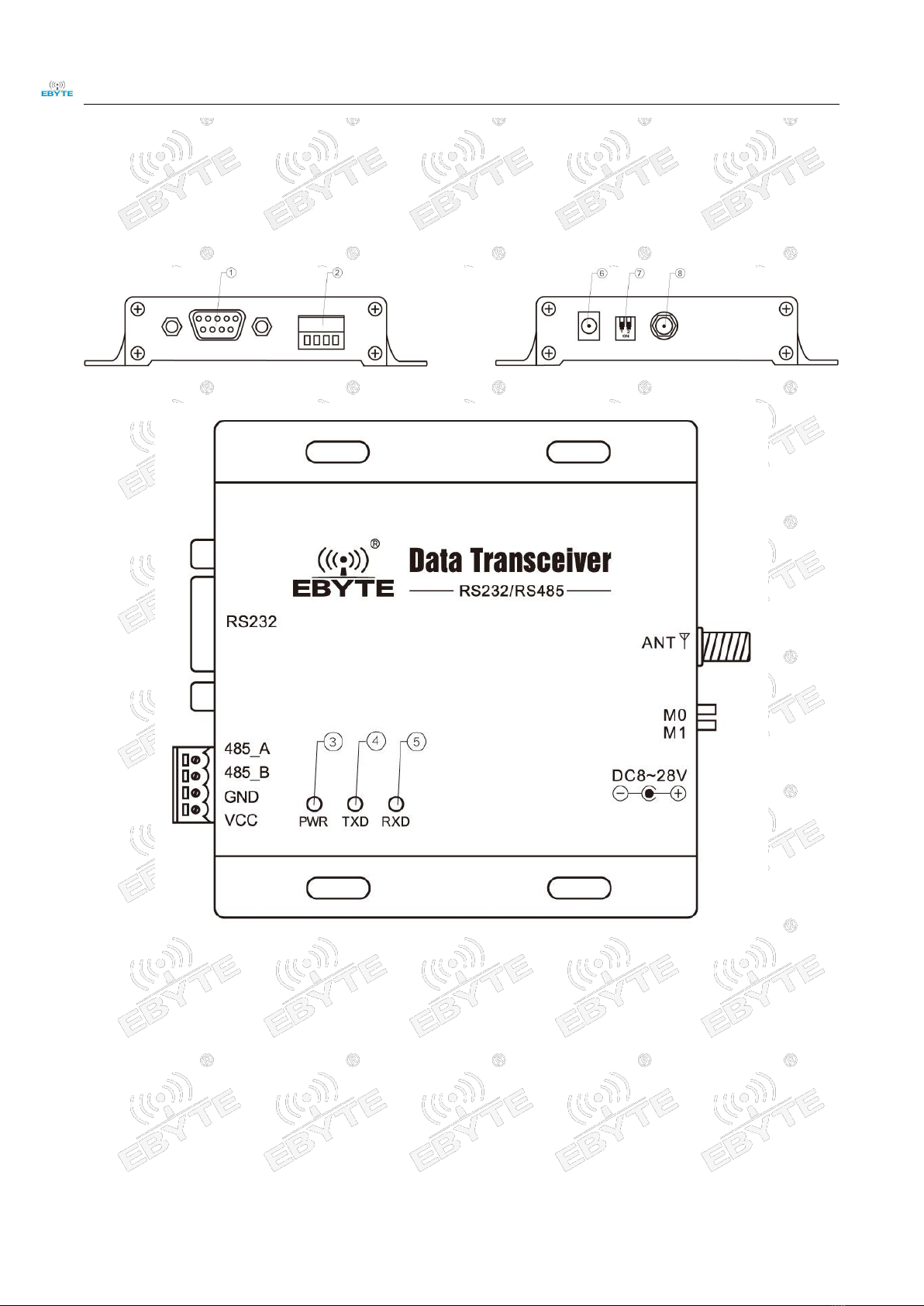
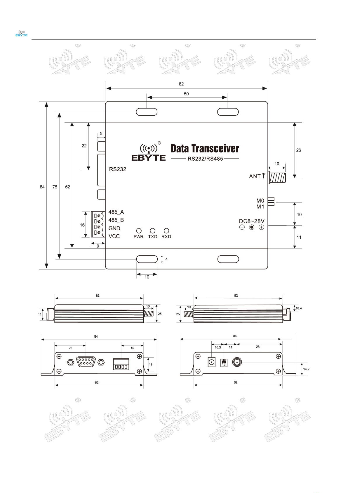
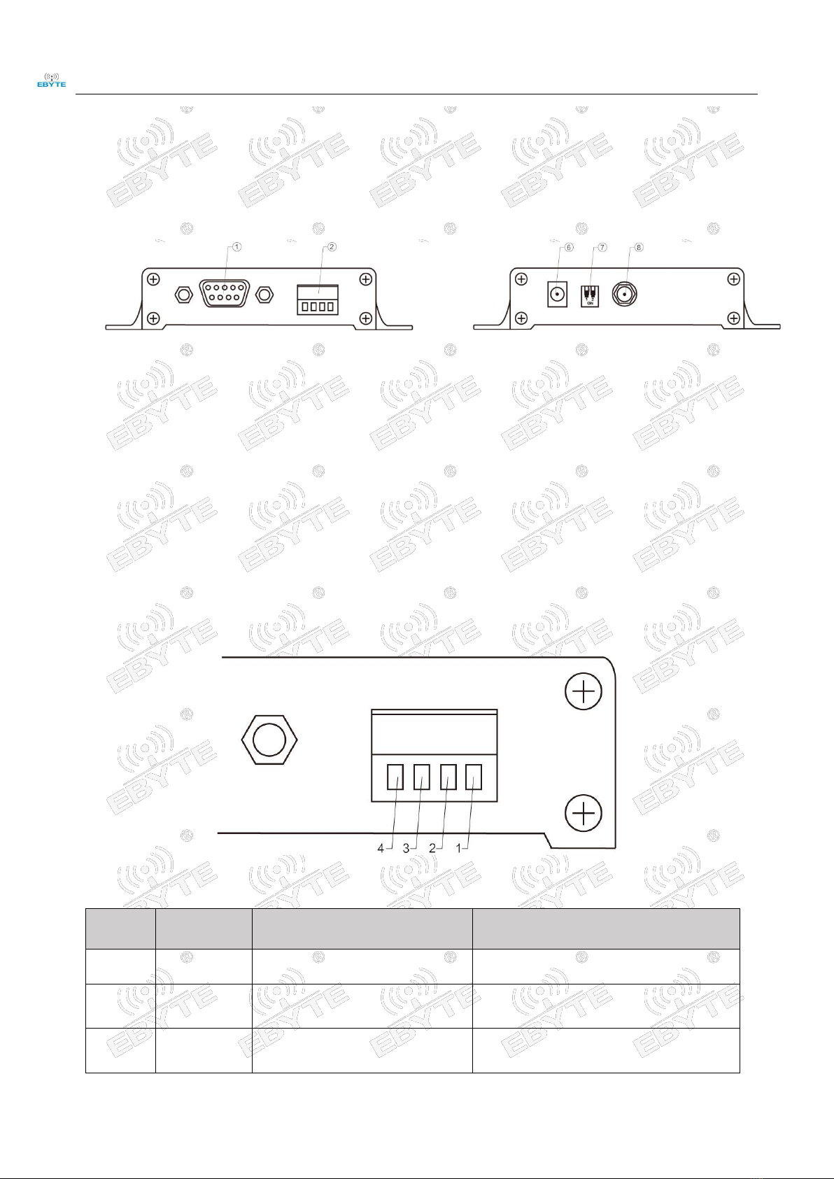
3.1.Structure............................................................................................................................................................5
3.2.Dimension.........................................................................................................................................................7
4.Interface Defination..................................................................................................................................................... 8
4.1.Power interface definition................................................................................................................................ 8
4.2.RS232 Interface definition................................................................................................................................8
4.3.RS485 Interface definition................................................................................................................................8
5. Technical indicators.................................................................................................................................................... 9
5.1.Model specifications.........................................................................................................................................9
5.2.General specification parameters..................................................................................................................... 9
5.3.Frequency range and channels........................................................................................................................10
5.4.Transmit power level...................................................................................................................................... 10
5.5.Air data rate.................................................................................................................................................... 10
5.6.Current parameters..........................................................................................................................................10
5.7.Transceiver Length and Sub-packing Mode...................................................................................................11
6. Operating mode.........................................................................................................................................................11
7. Connection diagram when programming................................................................................................................. 12
7.1.diagrammatic drawing.................................................................................................................................... 12
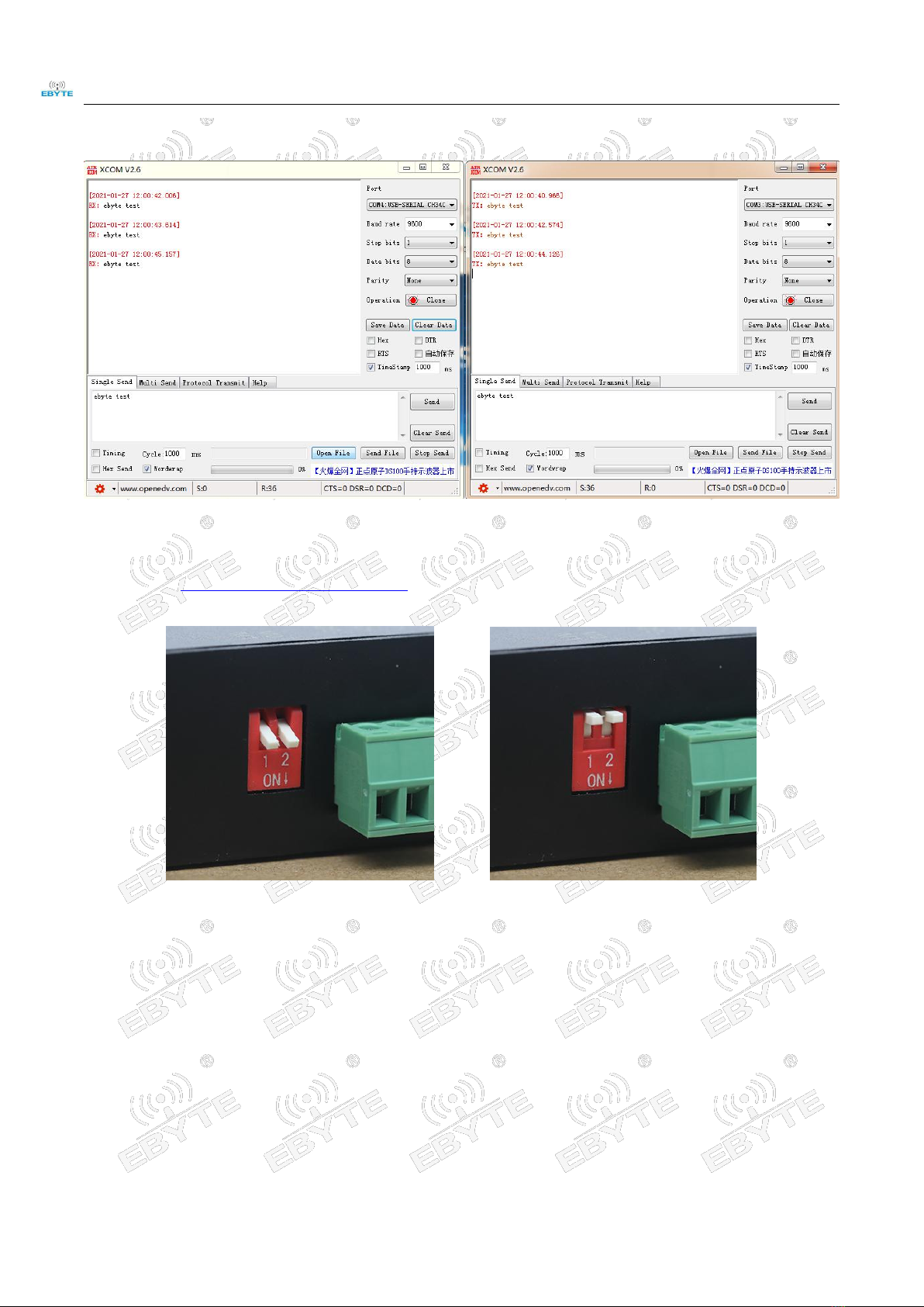
7.2.Parameter setting instruction.......................................................................................................................... 13
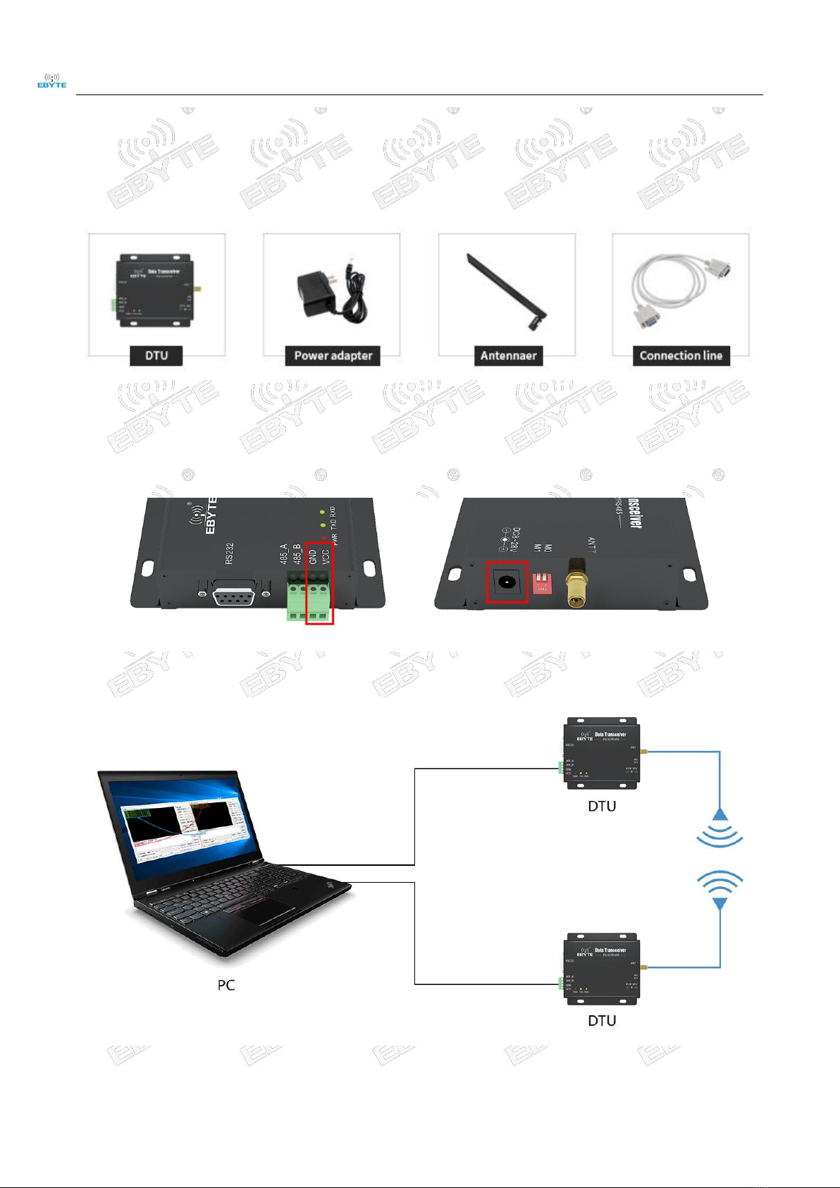
8. Connection diagram in test and application............................................................................................................. 14
9. E32-DTU series........................................................................................................................................................ 14
10.Practical application.................................................................................................................................................15
11.Note..........................................................................................................................................................................15
12.Important statement................................................................................................................................................. 16

Chengdu Ebyte Electronic Technology Co.,Ltd. E32-DTU (433L20) user manual
Copyright ©2012–2021,Chengdu Ebyte Electronic Technology Co,;Ltd 2
This manual may change with the continuous improvement of the product. Please refer to the latest version of the
instruction. Chengdu Ebyte Electronic Technology Co., Ltd. reserves all rights of final interpretation and modification of
this manual.
1.Introduction
1.1. Brief Introduction
E32-DTU (433L20) is a wireless data transceiver of 433M with standard RS232/RS485 connectors. They are
half-duplex. TX & RX modems with LoRa technology and transparent transmission mode. Voltage supply ranges from
8V to 28V, Working frequency: 425~450.5MHz (Default:433MHz).
The LoRa direct sequence spread spectrum technology enables the longer communication distance and better power
density concentration as well as superior anti-interference ability. The FEC algorism enables higher coding efficiency and
correction ability. The interfered data packets will be corrected proactively upon sudden interference, which significantly
improves reliability and communication distance. Without FEC, the interfered data packet will be dropped. The
transceivers feature data encryption and compression. The data transmitted in air features randomness, the rigorous
algorism makes data interception meaningless. The data compression function has possibility to reduce the data
transmission time, which in turn reduces the possibility of being interfered, thus improves the reliability and
communication efficiency.
1.2. Features
★All core components are originally imported, our transceiver modems have much advanced functions with smaller size
and lower cost.
★The top TX power is 100mW, all technical parameters meet European industrial standards.
★Temperature compensators are adopted to make the frequency stability better than ±1.5PPM.
★Operation temperature range: -40℃~+85℃, applicable for various harsh environment, it is real industrial grade
products.
★Aluminum alloy case, compact size, great heat dispersion; good shielding, prime electromagnetic compatibility and
strong anti-interference.
★Power reverse & overload protection and antenna surge protection functions significantly improve the reliability.
★Parameters can be configured by programming, such as TX power, frequency point, air data rate, address and so on.
★Ultra-low power consumption, standby current is only 28mA (even lower under power-saving and sleep modes), TX
current ≤0.2A .
★Embedded watch-dog and precise time layout, modem will restart automatically upon abnormal situation and work
with previous parameters.
★The transceivers adopt original SEMTECH SX1278 chip, customers highly comment the products because of the
super reliability.

Chengdu Ebyte Electronic Technology Co.,Ltd. E32-DTU (433L20) user manual
Copyright ©2012–2021,Chengdu Ebyte Electronic Technology Co,;Ltd 3
2. Operation
Main parts
1、First step is to mount antenna, then battery, making sure the dial switch is on its right status. User gets on the power
by choosing either VCC/GND or power adapter.
2、Using USB-(RS232) converter or USB-RS(485) converter or other way to link computer and DTU.

Chengdu Ebyte Electronic Technology Co.,Ltd. E32-DTU (433L20) user manual
Copyright ©2012–2021,Chengdu Ebyte Electronic Technology Co,;Ltd 4
3、Firing up two XCOMs, choosing Baud rate 9600bps, 8N1, the setting which serial port transmission can be
achieved.
4、User needs to open the mode switch first before link DTU with computer if the user want to modify parameters.
Firing up E32-DTU 数 传 电 台 配 置 软 件 (E32-DTU parameter configuration application) to modify related
parameters. The mode switch must be reopened to achieve transmission after the configuration.
Mode 0 Default Mode 3 Parameter setting

Chengdu Ebyte Electronic Technology Co.,Ltd. E32-DTU (433L20) user manual
Copyright ©2012–2021,Chengdu Ebyte Electronic Technology Co,;Ltd 5
3.Installation Specifications
3.1. Structure

Chengdu Ebyte Electronic Technology Co.,Ltd. E32-DTU (433L20) user manual
Copyright ©2012–2021,Chengdu Ebyte Electronic Technology Co,;Ltd 6
Pin
NO.
Name
Function
Description
1
DB-9 female socket
RS-232 interface
Standard RS-232 interface
2
3.81 terminal block
RS-485, power interface
Standard RS-485 interface and pressure line
power interface
3
PWR-LED
Power LED
Red, lit when the power is on
4
TXD-LED
Transmit LED
Yellow, blinks when sending data
5
RXD-LED
Receive LED
Yellow, blinks when receiving data
6
DC power interface
Power interface
In-line round hole, outer diameter 5.5mm,
diameter 2.5mm
7
DIP switch
DIP switch
Controlled by working mode
8
Antenna interface
SMA-K interface
external thread, 10mm, 50Ωcharacteristic
impedance

Chengdu Ebyte Electronic Technology Co.,Ltd. E32-DTU (433L20) user manual
Copyright ©2012–2021,Chengdu Ebyte Electronic Technology Co,;Ltd 7
3.2. Dimension
Unit:mm

Chengdu Ebyte Electronic Technology Co.,Ltd. E32-DTU (433L20) user manual
Copyright ©2012–2021,Chengdu Ebyte Electronic Technology Co,;Ltd 8
4.Interface Defination
4.1. Power interface definition
Users can choose ⑥DC power interface, using the power adapter supply with the interface of the 5.5mm outer
diameter , 2.5mm diameter ;
Also choose the VCC and GND terminal power supply, only choose any one of the power supply is OK;
E32-DTU can use 8~ 28V DC power supply, but it is recommended to use 12V or 24V DC power supply.
4.2. RS232 Interface definition
The E32-DTU can be connected to the device via RS-232 using the standard DB-9 interface.
4.3. RS485 Interface definition
E32-DTU can connect the 485_A terminal and 485_B terminal with the device RS-485 A terminal and B terminal.
★
Pin NO.
Definition
Function
Description
1
VCC
Crimping power interface, positive
8 ~ 28V DC, recommended 12V or 24V
2
GND
Crimping power interface, negative
The power supply negative pole is connected to
the system ground and the housing
3
485_B
RS-485 interface, interface B
The RS-485 interface B is connected to the
device interface B

Chengdu Ebyte Electronic Technology Co.,Ltd. E32-DTU (433L20) user manual
Copyright ©2012–2021,Chengdu Ebyte Electronic Technology Co,;Ltd 9
4
485_A
RS-485 interface, interface A
The RS-485 interface A is connected to the device
interface A
★Note: The transceiver will be in poor communication when connected to multiple devices , it is recommended to be
connected to a single device, please try to use parallel 120Ω resistor between 485_A terminal and 485_B.
5.Technical indicators
5.1. Model specifications
Model
Frequency
Transmit
power
Distance
Specifications
Application
Hz
W
km
E32-DTU
(433L20)
433
0.1
3
Strong penetration,
anti - interference
To the environment with small data,
long distance, many obstacles
★Note: Test condition: in clear and open air without shelters, 12V /2A power supply, 5dBi gain sucker antenna over 2
meters height from the ground, with the factory default parameters.
5.2. General specification parameters
NO.
Model
Specification
Description
1
Size(H*W*D)
82 * 62 * 25 mm
See more at 3.2 Dimension
2
Weight
131g
Tolerance: 4.5g
3
Temperature
-40℃~+70℃
Meet industrial level
4
Antenna impedance
50 Ω
Standard 50 Ω characteristic impedance
5
Supply voltage
+8 ~ +28V DC
It is recommended to use 12V or 24V
6
Communication interface
RS232/RS485
Standard DB9 hole / 3.81 terminal
block
7
Baud rate
Default 9600
from 1200 to 115200 bps
8
Address
Default 0
65536 configurable addresses

Chengdu Ebyte Electronic Technology Co.,Ltd. E32-DTU (433L20) user manual
Copyright ©2012–2021,Chengdu Ebyte Electronic Technology Co,;Ltd 10
5.3. Frequency range and channels
Model
Default frequency
Frequency range
Channel spacing
Channels
MHz
MHz
MHz
E32-DTU
(433L20)
433
410~441
1
32,half duplex
★Note: In the same area when multiple data transceivers are communicating one to one at the same time, it is
recommended to set the channel spacing between each group of data transceivers at 2MHz or more.
5.4. Transmit power level
Model
10mW
25mW
50mW
100mW
E32-DTU (433L20)
√
√
√
√
★Note: The lower the transmit power, the closer the transmission distance, but the working current won’t be declined in
exact proportion ,it is recommended to use the maximum transmit power.
5.5. Air data rate
Model
Default air data
rate
Levels
Air data rate(bps)
bps
bps
E32-DTU (433L20)
2.4
6
0.3、1.2、2.4、4.8、9.6、19.2
★Note: The higher the air data rate, the faster the transmission rate, the transmission distance is also closer; when the
rate meets the requirements, the lower air data rate, the better quality.
5.6. Current parameters
Model
Transmitting current mA
Standby current mA
12V
24V
12V
24V
E32-DTU (433L20)
134
81
28
28

Chengdu Ebyte Electronic Technology Co.,Ltd. E32-DTU (433L20) user manual
Copyright ©2012–2021,Chengdu Ebyte Electronic Technology Co,;Ltd 11
★Note: It is recommended to retain more than 50% of the current margin when selecting the power supply, which will
help the data transceiver to work steadily for a long time.
5.7. Transceiver Length and Sub-packing Mode
Model
Buffer
Sub-package
E32-DTU (433L20)
512Byte
Automatically send 58 bytes per package
★Note:
1. When the receiving data is more than a single packet capacity, the beyond part will be automatically assigned
to the second transmission until it is completed;
2. The data transceiver can not receive data which is more than the buffer capacity;
6.Operating mode
E32-DTU(170L30) has four operating modes, if low power consumption is not required, normal communication is
recommended to configure the data transceiver for the normal mode (mode 0);
The factory default is normal mode (mode 0).
Categories
M1
M0
Description
Mode 0
Normal Mode
ON
ON
Open UART and RF,transparent transmission
is on
Mode 1
Wake-up Mode
ON
OFF
Air wake-up mode, the packet comes with a
wake-up code,
Mode 2
Power-saving Mode
OFF
ON
The air wake-up receive mode, saving receive
power, the mode can not be transmitted
Mode 3
Sleep Mode
OFF
OFF
Parameter setting using the configuration
software
★Note: no need to care about the wake-up mode (mode 1) and power saving mode (mode 2) if it doesn’t request low
power consumption.

Chengdu Ebyte Electronic Technology Co.,Ltd. E32-DTU (433L20) user manual
Copyright ©2012–2021,Chengdu Ebyte Electronic Technology Co,;Ltd 12
7.Connection diagram when programming
7.1. diagrammatic drawing
Mode
M1
M0
Description
Mode 3
Sleep Mode
Off
Off
Only be programmed using the
configuration software in the current mode
★Note:
1.programming can only be carried on in a specific mode(see above), if fails, please confirm the work mode.
2.If there’s no complicated programming, opening the E32-DTU 数传电台配置软件(E32-DTU parameter configuration
application) to modify parameters.

Chengdu Ebyte Electronic Technology Co.,Ltd. E32-DTU (433L20) user manual
Copyright ©2012–2021,Chengdu Ebyte Electronic Technology Co,;Ltd 13
7.2. Parameter setting instruction
Parameter
Description
Baud rate
The serial port baud rate of a wireless data station at work,1200bps~115200bps。
Odd-even
check
Support 8N1:no check ;8E1:even-check;8O1:odd-check;Both are 8-bit data bits and 1-bit stop bits.
Air data rate
(bps)
Wireless communication rate, also known as air baud rate air rate high, data transmission speed, transmission of the same
data time delay is small, but the transmission distance will become shorter.
Transmitting
power
In order to ensure the working efficiency, it is recommended to use the maximum power. If the transmitted power is
reduced, the communication distance will become shorter and the required current will be reduced
FEC
The lost or interfered data can be partially corrected by complex encoding, which can improve the equivalent receiving
sensitivity by about 3dBm. Turning off this function can reduce the communication delay.
Transmission
mode
Transparent transmission, and send-as-received fixed points: data is sent at fixed points according to the format
Wake Up
Time
There is no direct relationship with the communication delay. If the customer needs low-power applications, this option
shall be adjusted as required. In the power-saving mode, the longer the wake-up time, the lower the power consumption
of the receiving end, and the greater the communication delay.
IO driven
By default, select the internal TTL signal drive mode。
Station
Address
Internal address of wireless data station, stations with the same address as those independent of Modbus address can
communicate with each other. This feature can be used to realize software filtering grouping input range :0~65535,
decimal number.

Chengdu Ebyte Electronic Technology Co.,Ltd. E32-DTU (433L20) user manual
Copyright ©2012–2021,Chengdu Ebyte Electronic Technology Co,;Ltd 14
Frequency
Channel
It is equivalent to the working frequency of the wireless data transmission station. Each channel corresponds to its
different working frequency. Theoretically, different frequency channels cannot communicate with each other,
If there are
multiple groups of wireless data stations in the same area, the communication frequency interval is suggested to be
2~5MHz.
8. Connection diagram in test and application
9. E32-DTU series
Mode No.
Interface
Frequency Hz
Tx power dBm
Distance km
Function feature
E32-DTU (433L37)
RS232 RS485
433M
37
20
LoRa spread spectrum, long
distance, anti - interference
E32-DTU (868L30)
RS232 RS485
868M
30
8
LoRa spread spectrum, long
distance, anti - interference
E32-DTU (915L30)
RS232 RS485
915M
30
8
LoRa spread spectrum, long
distance, anti - interference
E32-DTU (170L30)
RS232 RS485
170M
30
8
Strong Penetration, LoRa
spread spectrum, anti -
interference
E32-DTU (868L20)
RS232 RS485
868M
20
3
LoRa spread spectrum, long
distance, anti - interference
E32-DTU (915L20)
RS232 RS485
915M
20
3
LoRa spread spectrum, long
distance, anti - interference

Chengdu Ebyte Electronic Technology Co.,Ltd. E32-DTU (433L20) user manual
Copyright ©2012–2021,Chengdu Ebyte Electronic Technology Co,;Ltd 15
E32-DTU (433L30)
RS232 RS485
433M
30
8
LoRa spread spectrum, long
distance, anti - interference
E32-DTU (433L27)
RS232 RS485
433M
27
5
LoRa spread spectrum, long
distance, anti - interference
E32-DTU (433L20)
RS232 RS485
433M
20
3
LoRa spread spectrum, long
distance, anti - interference
10. Practical application
The data transceiver of CDEBYTE is applied for all kinds of point to point, one point to multiple points wireless
data transmission system, such as smart home, Internet of things transformation, power load monitoring, distribution
network automation, hydrological and hydrological forecasting, water pipe network monitoring, urban street lamps
Monitoring, air defense alarm control, railway signal monitoring, centralized control of railway water supply, oil supply
pipe network monitoring, GPS system, remote meter reading, electronic crane, automatic reporting, seismic forecasting,
fire prevention, environmental monitoring and other industrial automation system, as shown below:
11. Note
1. Please keep the warranty card of the equipment which includes the factory number (and important technical
parameters) and is important for user's future maintenance and new equipment.
2. Transceiver during the warranty period, if the quality of the product itself rather than man-made damage or

Chengdu Ebyte Electronic Technology Co.,Ltd. E32-DTU (433L20) user manual
Copyright ©2012–2021,Chengdu Ebyte Electronic Technology Co,;Ltd 16
lightning and other natural disasters caused by damage, enjoys free warranty; please do not repair by yourself, the
problem and please contact with our company when problem occurring, we offer the first-class after-sales service.
3. Please do not operate the transceiver in some flammable places such as coal mines or near explosive atmospheres
(such as detonators).
4. Please use the appropriate DC power supply, high frequency interference ability, small ripple, and enough load
capacity are required; it’s better to have over current, over voltage protection and lightning protection and other functions
to ensure that transceiver working properly.
5. Please do not use it in the working environment beyond the transceiver environmental characteristics , such as
high temperature, humidity, low temperature, strong electromagnetic fields or dust larger environment.
6. Please do not continuously keep transceiver to transmit in full capacity, or the transmitter might be damaged.
7. Please connect the ground with the external ground of the power supply (such as PC, PLC, etc.) , otherwise it is
easy to burn out the communication interface; do not plug the interface with power supplying.
8. When testing, please connect the antenna or 50 Ω load, otherwise transceiver will be damaged easily ;the
distance from the antenna is better than 2 meters, so as to avoid harm, please do not touch the antenna when transmitting.
9. Wireless data transceiver has different communication distance in different environments, communication
distance is influenced by temperature, humidity, obstacle density, obstacle volume and electromagnetic environment; in
order to ensure stable communication, it is recommended to reserve at least 50 % of the communication distance.
10. When communication distance is not perfect, it is recommended to improve the antenna quality and the
11. When choosing power supply, it is recommended to keep at least 50% current left and the ripple must not
exceed 100mV.
12. Important statement
1. CDEBYTE reserves the right of final interpretation and modification of all the contents of this manual.
2. As the hardware and software products continuously improving, this manual may subject to change without notice,
please refer to the latest version.
3. Everyone is responsible for protecting the environment: to reduce the use of paper, we only provide electronic
documents of the English manual, if necessary, please go to our official website to download; In addition, for special
requirements, we agree to offer certain amount of documents according to order quantity, not every data transceiver are
supplied with one manual, please understand;
Revision history
Version
Date
Description
Issued by
1.0
2018/8/30
Initial version
huaa
1.1
2019/4/2
Model No. split
molly

Chengdu Ebyte Electronic Technology Co.,Ltd. E32-DTU (433L20) user manual
Copyright ©2012–2021,Chengdu Ebyte Electronic Technology Co,;Ltd 17
1.3
2020/12/24
Model No. split
LI
1.4
2021/1/27
Model No. split
LY
About us
Technical support: support@cdebyte.com
Documents and RF Setting download link: www.ebyte.com
Thank you for using Ebyte products! Please contact us with any questions or suggestions: info@cdebyte.com
-------------------------------------------------------------------------------------------------
Fax: 028-64146160
Web: www.ebyte.com
Address:BuildingB5,MouldIndustrialPark,199#XiquAve,WestHigh-techZone,Chengdu,611731,Sichuan,China
Other manuals for E32-DTU
3
This manual suits for next models
1
Table of contents
Other Ebyte Modem manuals

Ebyte
Ebyte E70-DTU User manual

Ebyte
Ebyte E78-DTU(470LN22) User manual

Ebyte
Ebyte E90-DTU User manual

Ebyte
Ebyte Wireless Modem User manual

Ebyte
Ebyte E90-DTU User manual

Ebyte
Ebyte E851-RTU User manual

Ebyte
Ebyte ECAN-401S User manual

Ebyte
Ebyte E870-E1 User manual

Ebyte
Ebyte ME31-XAAX0440 User manual

Ebyte
Ebyte E810-DTU User manual

Ebyte
Ebyte E851-RTU User manual

Ebyte
Ebyte E821-RTU User manual

Ebyte
Ebyte E90-DTU User manual

Ebyte
Ebyte ME31-XXXA0006 User manual

Ebyte
Ebyte ME31-XXAX0060 User manual

Ebyte
Ebyte E90-DTU User manual

Ebyte
Ebyte E180-DTU User manual

Ebyte
Ebyte M31 Series User manual

Ebyte
Ebyte E34-DTU User manual

Ebyte
Ebyte E840-DTU User manual