Ecco DuoBeam User manual

Page 1 of 12
IMPORTANT! Read all instructions before installing and using. Installer: This manual must be
delivered to the end user. This manual assumes installation by a suitably qualied Automotive Technician.
The ECCO LED DuoBeam™ uses state of the art LEDs and optics
to provide superior optical output. The rugged design and long
life capabilities make it virtually maintenance free. When properly
configured, the DuoBeam™ will exceed SAE Class 1 and California
Title 13 requirements.
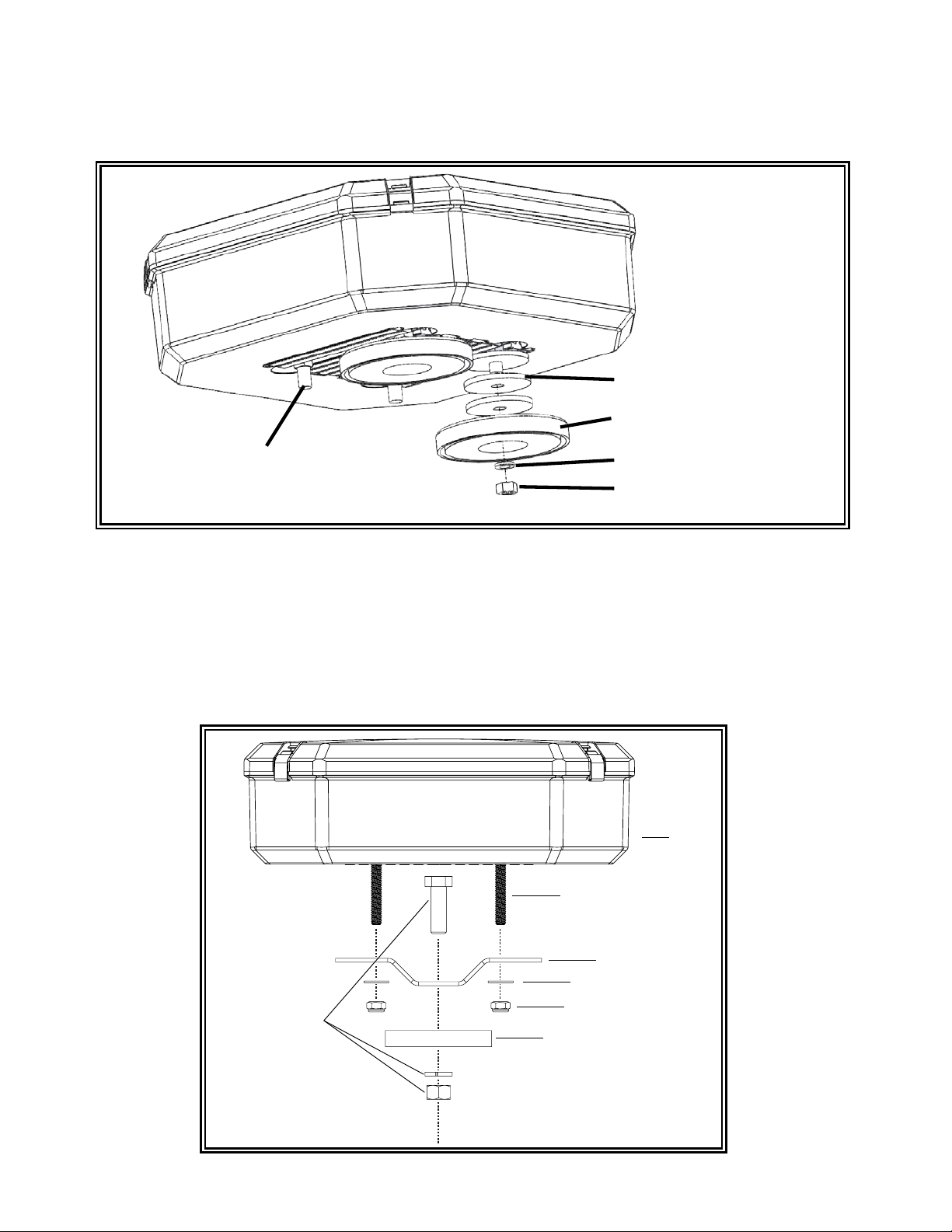
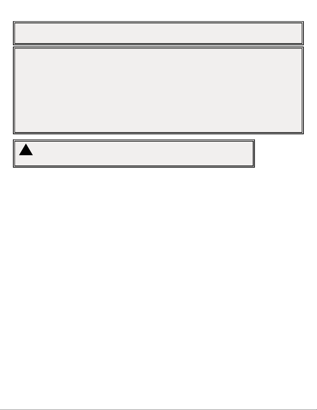
Unpacking and Pre-Installation:
Carefully remove the lightbar and place it on a at surface. Examine the unit for transit damage and locate all parts. If damage is found or
parts are missing, contact the transit company or ECCO. Do not use damaged or broken parts.
Ensure the lightbar voltage is compatible with the planned installation.
Installation and Operation Instructions
DuoBeam™
WARNING!
Failure to install or use this product according to manufacturer’s recommendations may result in property
damage, serious bodily/personal injury, and/or death to you and those you are seeking to protect!
!
Do not install and/or operate this safety product unless you have read and understand the safety
information contained in this manual.
1. Proper installation combined with operator training in the use, care and maintenance of emergency warning devices are essential to
ensure the safety of emergency personnel and the public.
2. Emergency warning devices often require high electrical voltages and/or currents. Exercise caution when working with live electrical
connections.
3. This product must be properly grounded. Inadequate grounding and/or shorting of electrical connections can cause high current
arcing, which can cause personal injury and/or severe vehicle damage, including re.
4. Proper placement and installation is vital to the performance of this warning device. Install this product so that output performance of
the system is maximized and the controls are placed within convenient reach of the operator so that s/he can operate the system
without losing eye contact with the roadway.
5. It is the responsibility of the vehicle operator to ensure daily that all features of this product work correctly. In use, the vehicle operator
should ensure the projection of the warning signal is not blocked by vehicle components (i.e., open trunks or compartment doors),
people, vehicles or other obstructions.
6. The use of this or any other warning device does not ensure all drivers can or will observe or react to an emergency warning signal.
Never take the right-of-way for granted. It is your responsibility to be sure you can proceed safely before entering an intersection, drive
against trafc, respond at a high rate of speed, or walk on or around trafc lanes.
7. This equipment is intended for use by authorized personnel only. The user is responsible for understanding and obeying all laws
regarding emergency warning devices. Therefore, the user should check all applicable city, state, and federal laws and regulations.
The manufacturer assumes no liability for any loss resulting from the use of this warning device.
8. This product may contain high intensity LEDs staring directly into these lights could result in temporary and/or permanent vision
impairment.

Page 2 of 12
Installation & Mounting:
Mounting
Before proceeding with installation, plan all wiring and cable routing. For orientation purposes, the DuoBeam™ was built with the carriage
bolt track running from left to right (not front to back). The mounting location for the lightbar should be chosen such that the lightbar is level
and visibility to approaching trafc is optimized.
Caution:
When drilling into any vehicle surface, make sure that the area is free from any electrical wires, fuel lines, vehicle upholstery, vehicle
support members, etc. that could be damaged.
!
Permanent Mount
1. Insert carriage bolts into track
2. Place spacer over bolts as shown in FIGURE 1.
3. Align bolts with pre-drilled holes in the vehicle’s surface.
4. Place lock washer and nut on bolt and tighten until secure.
Specications:
Dimensions: 10.3” x 10.3” x 3.3”
Average Weight: 6 lbs.
Input Voltage: 10-16 VDC
Nominal Current @ 12.8VDC:
6 LED Module: 0.5 A max.
8 LED Module: 1.0 A max.
9 LED Module: 1.0 A max.
12 LED Module: 1.5 A max.
Flash Rate: See Wiring Section
Temp. Range: -22°F to 122°F
-30°C to 50°C
MOUNTING SPACER
5/16-18” x 1 1/2” CARRIAGE BOLT
VEHICLE MOUNTING SURFACE
5/16” SPLIT LOCK WASHER
5/16-18” SS HEX NUT
FIGURE 1

Page 3 of 12
Magnet Mount
1. Insert carriage bolts into track.
2. Place oversized washers over bolts as shown in FIGURE 2.
3. Attach magnetic base over bolts.
4. Place lock washer and nut on bolt and tighten until secure.
OVERSIZED WASHERS
MAGNETIC BASE
5/16” SPLIT WASHER
5/16-18” SS HEX NUT
5/16-18” x 1 1/2” CARRIAGE BOLT
FIGURE 2
Pylon/Headache Rack Mounting
1. Insert the four (4) 5/16”-18 carriage bolts in the channels on the under side of the light bar and loosely attach the mounting brackets.
2. Place the lightbar on the vehicle and slide the mounting brackets into position.
3. Secure the brackets to the lightbar with the supplied washers and nuts as shown in FIGURE 3.
4. With the mounting brackets positioned, mark the locations of the mounting hole centers on the roof of the vehicle. Remove the bar and
drill the mounting holes as marked.
5. Secure the mounting brackets to the vehicle with customer supplied hardware.
1/2” BOLT AND MOUNTING
HARDWARE SUPPLIED BY
CUSTOMER MOUNTING SURFACE
5/16-18 NUT
OVERSIZED FLAT WASHER
BRACKET
5/16-18 CARRIAGE BOLT
LIGHTBAR
FIGURE 3

Page 4 of 12
Mirror Mount Bracket
1. Assemble the brackets. Tighten the 3/8” bolt, but leave the 7/16” bolt nger tight at this time.
2. Position bracket assembly on top mirror supports, bracket A on rear support and bracket B on front support. Note: some mirror designs
require reversing bracket A and B. Rotate bracket A as necessary to get the best t. Some additional bending of brackets may be
necessary in some cases to achieve a satisfactory t.
3. Attach bracket assembly to mirror supports with U-bolts. Position bracket assembly as desired and tighten U-bolts. The DuoBeam™
mounting bracket should be parallel to the ground.
4. Insert two carriage bolts into underside of the DuoBeam™ bracket. Secure the unit to the top of the DuoBeam™ bracket.
FIGURE 4
7/16” LONG BOLT
DUOBEAM MOUNTING BRACKET
SUPPORT MOUNTING BRACKET
MOUNTING BRACKET (B)
MOUNTING BRACKET (A)
U-BOLT
3/8” LONG BOLT

Page 5 of 12
Notes:
1. Larger wires and tight connections will provide longer service life for components. For high current wires it is highly recommended
that terminal blocks or soldered connections be used with shrink tubing to protect the connections. Do not use insulation displacement
connectors (e.g., 3M Scotchlock type connectors).
2. Route wiring using grommets and sealant when passing through compartment walls. Minimize the number of splices to reduce
voltage drop. High ambient temperatures (e.g., under-hood) will signicantly reduce the current carrying capacity of wires, fuses, and
circuit breakers. All wiring should conform to the minimum wire size and other recommendations of the manufacturer and be protected
from moving parts and hot surfaces. Looms, grommets, cable ties, and similar installation hardware should be used to anchor and
protect all wiring.
3. Fuses or circuit breakers should be located as close to the power takeoff points as possible and properly sized to protect the wiring
and devices.
4. Particular attention should be paid to the location and method of making electrical connections and splices to protect these points from
corrosion and loss of conductivity.
5. Ground termination should only be made to substantial chassis components, preferably directly to the vehicle battery.
6. Circuit breakers are very sensitive to high temperatures and will “false trip” when mounted in hot environments or operated close to
their capacity.
Important!
This unit is a safety device and it must be connected to its own separate, fused power point to assure its continued operation should any
other electrical accessory fail. Do not wire in parallel with any other accessory.
Wiring Instructions:
Caution:
Disconnect the battery before wiring up the lightbar, to prevent accidental shorting, arcing and/or electrical shock.
!
IF Series Wiring
An IF series DuoBeam™ has a dedicated ground wire and one or more +power wires routed to the modules. The black ground
wire should be connected directly to the battery. The amp ratings for each module type are detailed in the specications secion
of this installation guide.

Page 6 of 12
FIGURE 5
IF Series Flash Pattern Selection
PriZm™ Flash Patterns
Order Flash Pattern
1 Cycle Flash (Default)
2 NFPA Quad Flash 80 FPM
3 Steady Burn
4 Single Flash 75 FPM
5 Single Flash 150 FPM
6 Single Flash 300 FPM
7 Double Flash 75 FPM
8 Double Flash 150 FPM
9 Triple Pop Flash 75 FPM
10 Triple Flash 150 FPM
11 Quad Pop Flash 75 FPM
12 Quad Pop Flash 150 FPM
13 Five Flash 70 FPM
14 Five Flash 150 FPM
15 Modular Flash
The DuoBeam can be populated with one of two different module types - PriZm™ or Torus™. For PriZm™ (8 or 12 LED) style modules, the
ash pattern on each individual module can be cycled to the next ash pattern (shown in TABLE 1) by briey shorting together the 2 short
pads with a wire or the blade of a screwdriver as shown in FIGURE 5. The modules can be reset to the default ash pattern by shorting the
pads together for longer than 5 seconds. A thin layer of conformal coat may need to be scraped from the surface of the short pads if the
modules aren’t changing patterns easily.
TABLE 1
SHORT PADS

Page 7 of 12
Torus™ Flash Patterns
Order Flash Pattern
1 Cycle Flash (Default)
2 NFPA Quad Flash 80 FPM
3 Quad Pop Flash 70 FPM
4 Steadyburn
5 Five Flash 70 FPM
6 Triple Flash 70 FPM
7 Double Flash 70 FPM
8 Single Flash 70 FPM
9 Quad Pop Flash 70 FPM
10 Triple Pop Flash 70 FPM
11 Mod Flash
12 Cycle Flash 150 FPM
13 Five Flash 150 FPM
14 Quad Flash 150 FPM
15 Triple Flash 150 FPM
16 Double Flash 150 FPM
17 Single Flash 150 FPM
18 Single Flash 250 FPM
19 Single Flash 375 FPM
TABLE 2
FIGURE 6
For Torus™ (6 or 9 LED) style modules, the ash pattern on each individual module can be cycled to the next ash pattern (shown in Table 2)
by momentarily shorting together the JP1 pins with a wire or the blade of a screwdriver as shown in FIGURE 6. The module will reset to the
default ash pattern when the JP1 pins are shorted together for 5 seconds or more. Module pairs connected by a sync wire must be individu-
ally set to the same ash pattern to properly synchronize.

Page 8 of 12
TR Series Wiring
A TR series DuoBeam™ has a single cable with 7 colored wires. A dedicated ground wire, a dedicated power wire and ve colored control
wires which run through the main driver board.
The 16 AWG black ground wire should be connected directly to the battery. The 16 AWG red power wire requires a constant 10 to 16V(+)
power source with a customer supplied in line 15A fuse.
The ve control cable wires (listed in TABLE 3 below) routed through the driver board carry only low current (30 mA average) input signals to
control the DuoBeam™ functions and must be routed to the output of a control switch (or directly to multiple switches).
TABLE 3
Emergency Mode Flash Pattern Selection
There are seven customizable emergency ash pattern modes available based on the wire combinations shown in TABLE 4. When using
individual switches, make sure to congure all possible switch combinations.
To change a ash pattern on a single emergency level mode:
1. Power-up the unit and apply +power to the level mode wire(s) you wish to change (see TABLE 4). The unit will ash the default pattern.
2. Momentarily touch the GRN pattern select wire to (+) power to cycle through to the next ash pattern shown on TABLE 5.
3. To reset the ash pattern to the factory default, hold the GRN pattern select wire to (+) power for ~5 seconds.
Standard TR Function Wire Denitions
Function Wire Color Function Description
BLU L1 Level 1 Emergency Mode
ORG L2 Level 2 Emergency Mode
YEL L3 Level 3 Emergency Mode
GRN Pattern Select
WHT Lightbar Dim Set LEDs to DIM mode
Notice: When the GRN Pattern Select wire is connected to +power alone, test mode is enabled to excercise all outputs in
sequence.
Level Mode Combinations
Flash Pattern Modes Function Wire Color(s) Pattern Description FPM
L1 BLU 1 Cycle Flash Simultaneous 70
L2 ORG 1 Cycle Flash Simultaneous 70
L3 YEL 1 Cycle Flash Simultaneous 70
L1 + L2 BLU & ORG 1 Cycle Flash Simultaneous 70
L1 + L3 BLU & YEL 1 Cycle Flash Simultaneous 70
L2 + L3 ORG & YEL 1 Cycle Flash Simultaneous 70
L1 + L2 + L3 BLU, ORG & YEL 1 Cycle Flash Simultaneous 70
TABLE 4

Page 9 of 12
TABLE 5
Level Mode Flash Patterns
Order Flash Pattern - Module Group
1 Cycle Flash Simultaneous 70 FPM
2 Cycle Flash Alternating 70 FPM
3 NFPA Quad Flash Simultaneous 80 FPM
4 NFPA Quad Flash Alternating 80 FPM
5 Triple Flash Simultaneous 70 FPM
6 Triple Flash Alternating 70 FPM
7 Double FLash Simultaneous 70 FPM
8 Double FLash Alternating 70 FPM
9 Variable Single Flash Simultaneous
10 Variable Single Flash Alternating
11 Cycle Flash Simultaneous 150 FPM
12 Cycle Flash Alternating 150 FPM
13 Single Flash Simultaneous 250 FPM
14 Single Flash Alternating 250 FPM
15 Rotate
16 Cruise
For instructions related to the California Title 13 steady burning red warning lamp requirement during level mode operation, please contact
ECCO directly.

Page 10 of 12
Description Part No.
Lenses
Lower Amber 250-0484-02
Lower Clear 250-0484-03
Lower Red 250-0484-04
Upper Amber 250-0433-02
Upper Clear 250-0433-03
Upper Red 250-0433-04
Upper Black 250-0433-07
Mounting
Permanent Mounting Kit 140-9937-00
Pylon/Headache Rack Mount Kit EZ21DBPM
Magnet Mount Kit EZ21DBMG
Mirror Mount Kit EZ21DBMM
Accessories
Lens Retaining Clip EZ2127LC
Lens Retaining Clip, Black EZ2127LCB
Modules
TR6 (centrally controlled) EZ21CC6X*
TR9 (centrally controlled) EZ21CC9X*
TR6 (independent ashing) EZ21IF6X*
TR9 (independent ashing) EZ21IF9X*
REF8 (centrally controlled) EZ27CC8X*
REF12 (centrally controlled) EZ27CC12X*
REF8 (independent ashing) EZ27IF8X*
REF12 (independent ashing) EZ27IF12X*
Replacement Parts/Accessories:
*Where X indicates color options: A=Amber, B=Blue, C=Clear (White), G=Green, R=Red
Contact ECCO for Multicolor Options.

Page 11 of 12
Options and Maintenance:
Lens Cleaning
Occasional cleaning of the lenses will ensure optimum light output. Take care when cleaning lenses - although tough, polycarbonate
scratches easily. Clean the lens and base with soap and water or a lens polish using a soft cloth. Do not use solvents as they may damage
the polycarbonate.
Lens Removal and Installation
1. Uninstall the lens clips using a at blade screwdriver.
2. Insert the screwdriver into the gap along the lens edge, and twist the screwdriver to lift the lens.
3. When nished, reinstall making sure the lens gasket is not damaged or folded. Replace the clips by hooking into the bottom lens slot and
pressing the upper portion into the clip pocket.
LED Module Removal and/or Replacement
1. Remove screw(s) securing the mounting bracket to the extrusion.
2. Lift the light head assembly and disconnect wiring at the connectors.
3. Remove screw(s) securing the light head assembly to the mounting bracket.
4. During re-assembly, repeat the prior steps in reverse order. Torque screw(s) securing the light head assembly to the mounting bracket
using 10 in-lbs. Torque screws securing the mounting bracket to the extrusion using 50 in-lbs.
Troubleshooting:
All lightbars are thoroughly tested prior to shipment. However, should you encounter a problem during installation or during the life of the product, follow the
guide below for troubleshooting and repair information. If the problem cannot be rectied using the solutions given below, additional information may be
obtained from the manufacturer – contact details are at the end of this document.
PROBLEM POSSIBLE CAUSE SOLUTION
Does not function Poor power or ground connection In CC Lightbars, a green light on the central
control board should ash when power is
rst applied to the bar and during ash pat-
tern selection.
Blown fuse Check wiring, replace fuse
Incorrect ash patterns Wrong ash conguration Cycle through ash patterns according to
the supplied wire key and wiring instruc-
tions section of this installation guide.
NOTE: Operating the vehicle without the outer lens installed on the product may result in damage that will NOT be
covered under the warranty.
!

Page 12 of 12
833 West Diamond St
Boise, Idaho 83705
Customer Service
USA 800-635-5900
UK +44 (0)113 237 5340
AUS +61 (0)3 63322444
www.eccoesg.com
920-0467-00 Rev. A
Electronics Controls Company “ECCO” (Manufacturer)
ECCO warrants that on the date of purchase, this product will conform to ECCO’s specications for this product (which are
available from ECCO upon request). This Limited Warranty extends for Sixty (60) months from the date of purchase.
DAMAGE TO PARTS OR PRODUCTS RESULTING FROM TAMPERING, ACCIDENT, ABUSE, MISUSE, NEGLIGENCE, UN-
APPROVED MODIFICATIONS, FIRE OR OTHER HAZARD; IMPROPER INSTALLATION OR OPERATION; OR NOT BEING
MAINTAINED IN ACCORDANCE WITH THE MAINTENANCE PROCEDURES SET FORTH IN ECCO’S INSTALLATION AND
OPERATING INSTRUCTIONS VOIDS THIS LIMITED WARRANTY.
Exclusion of Other Warranties:
ECCO MAKES NO OTHER WARRANTIES, EXPRESSED OR IMPLIED. THE IMPLIED WARRANTIES FOR MERCHANT-
ABILITY, QUALITY OR FITNESS FOR A PARTICULAR PURPOSE, OR ARISING FROM A COURSE OF DEALING, US-
AGE OR TRADE PRACTICE ARE HEREBY EXCLUDED AND SHALL NOT APPLY TO THE PRODUCT AND ARE HEREBY
DISCLAIMED, EXCEPT TO THE EXTENT PROHIBITED BY APPLICABLE LAW. ORAL STATEMENTS OR REPRESENTA-
TIONS ABOUT THE PRODUCT DO NOT CONSTITUTE WARRANTIES.
Remedies and Limitation of Liability:
ECCO’S SOLE LIABILITY AND BUYER’S EXCLUSIVE REMEDY IN CONTRACT, TORT (INCLUDING NEGLIGENCE), OR
UNDER ANY OTHER THEORY AGAINST ECCO REGARDING THE PRODUCT AND ITS USE SHALL BE, AT ECCO’S DIS-
CRETION, THE REPLACEMENT OR REPAIR OF THE PRODUCT, OR THE REFUND OF THE PURCHASE PRICE PAID BY
BUYER FOR NON-CONFORMING PRODUCT. IN NO EVENT SHALL ECCO’S LIABILITY ARISING OUT OF THIS LIMITED
WARRANTY OR ANY OTHER CLAIM RELATED TO THE ECCO’S PRODUCTS EXCEED THE AMOUNT PAID FOR THE
PRODUCT BY BUYER AT THE TIME OF THE ORIGINAL PURCHASE. IN NO EVENT SHALL ECCO BE LIABLE FOR LOST
PROFITS, THE COST OF SUBSTITUTE EQUIPMENT OR LABOR, PROPERTY DAMAGE, OR OTHER SPECIAL, CONSE-
QUENTIAL, OR INCIDENTAL DAMAGES BASED UPON ANY CLAIM FOR BREACH OF CONTRACT, IMPROPER INSTAL-
LATION, NEGLIGENCE, OR OTHER CLAIM, EVEN IF ECCO OR A REPRESENTATIVE OF ECCO HAS BEEN ADVISED OF
THE POSSIBILITY OF SUCH DAMAGES. ECCO SHALL HAVE NO FURTHER OBLIGATION OR LIABILITY WITH RESPECT
TO THE PRODUCT OR ITS SALE, OPERATION AND USE, AND ECCO NEITHER ASSUMES NOR AUTHORIZES THE AS-
SUMPTION OF ANY OTHER OBLIGATION OR LIABILITY IN CONNECTION WITH SUCH PRODUCT.
This Limited Warranty denes specic legal rights. You may have other legal rights which vary from jurisdiction to jurisdiction.
Some jurisdictions do not allow the exclusion or limitation of incidental or consequential damages.
Table of contents
Other Ecco Lighting Equipment manuals

Ecco
Ecco 3800 Series Owner's manual

Ecco
Ecco Pro Vantage 12+ Series Installation instructions

Ecco
Ecco EW4009 Owner's manual

Ecco
Ecco Evolution Series User manual

Ecco
Ecco ED3777 Series Owner's manual

Ecco
Ecco ED3744 User manual

Ecco
Ecco Axios User manual

Ecco
Ecco EW3108-F Owner's manual

Ecco
Ecco ED3789 Owner's manual

Ecco
Ecco 7950 Owner's manual

Ecco
Ecco ED3700 Owner's manual

Ecco
Ecco ED3704 Owner's manual

Ecco
Ecco Pro Vantage 12+ Series User manual

Ecco
Ecco ED5051VDL Series User manual

Ecco
Ecco Reflex 5590 Series User manual

Ecco
Ecco EW01 Series Installation instructions

Ecco
Ecco 10 Series User manual

Ecco
Ecco ED3779 Series User manual

Ecco
Ecco 21 Series User manual

Ecco
Ecco 200 Series Manual