manuals.online logo
Brands
  1. Home
  2. •
  3. Brands
  4. •
  5. Ecco
  6. •
  7. Lighting Equipment
  8. •
  9. Ecco ED3704 Owner's manual

Ecco ED3704 Owner's manual

Page 1 of 4
IMPORTANT! Read all instructions before installing and using. Installer: This manual must be delivered to the end user.
WARNING!
Failure to install or use this product according to manufacturer’s recommendations may result in property damage, serious injury, and/or
death to those you are seeking to protect!
Installation and Operation Instructions
ED3703, ED3704 and ED3705 Series
LED Directionals
Size:
ED3703 3.63”L x 1.38”W x 0.75”H
ED3704 4.69”L x 1.38”W x 0.75”H
ED3705 6.19”L x 1.38”W x 0.75”H
Weight:
ED3703 0.10 lbs.
ED3704 0.13 lbs.
ED3705 0.18 lbs.
Voltage Range: 12-24 VDC
Current draw at 12.8 VDC:
ED3703 0.44 A. Max.
ED3704 0.60 A. Max.
ED3705 0.86 A. Max.
Power Consumption at 12.8 VDC:
ED3703 5.6 W. Max
ED3704 7.7 W. Max
ED3705 11.0 W. Max
Temperature Range:
-40° to 149°F
-40° to 65°C
Flash Rate:
See Flash Pattern Charts
Prior to Installation:
Carefully remove the unit from its packaging. If damage is found, contact the transit company or ECCO. Do not use broken or damaged parts. Prior to mounting, con-
sideration should be given to cable location.
Do not install and/or operate this safety product unless you have read and understood the safety information
contained in this manual.
1. Proper installation combined with operator training in the use, care, and maintenance of emergency warning devices are essential to
ensure the safety of emergency personnel and the public.
2. Emergency warning devices often require high electrical voltages and/or currents. Exercise caution when working with live electrical
connections.
3. This product must be properly grounded. Inadequate grounding and/or shorting of electrical connections can cause high current arcing,
which can cause personal injury and/or severe vehicle damage, including re.
4. Proper placement and installation is vital to the performance of this warning device. Install this product so that output performance of
the system is maximized and the controls are placed within convenient reach of the operator so that they can operate the system without
losing eye contact with the roadway.
5. Do not install this product or route any wires in the deployment area of an air bag. Equipment mounted or located in an air bag
deployment area may reduce the e󰀨ectiveness of the air bag or become a projectile that could cause serious personal injury or death.
Refer to the vehicle owner’s manual for the air bag deployment area. It is the responsibility of the user/operator to determine a suitable
mounting location ensuring the safety of all passengers inside the vehicle particularly avoiding areas of potential head impact.
6. It is the responsibility of the vehicle operator to ensure daily that all features of this product work correctly. In use, the vehicle operator
should ensure the projection of the warning signal is not blocked by vehicle components (i.e., open trunks or compartment doors),
people, vehicles or other obstructions.
7. The use of this or any other warning device does not ensure all drivers can or will observe or react to an emergency warning signal.
Never take the right-of-way for granted. It is the vehicle operator’s responsibility to be sure they can proceed safely before entering an
intersection, drive against tra󰀩c, respond at a high rate of speed, or walk on or around tra󰀩c lanes.
8. This equipment is intended for use by authorized personnel only. The user is responsible for understanding and obeying all laws
regarding emergency warning devices. Therefore, the user should check all applicable city, state, and federal laws and regulations. The
manufacturer assumes no liability for any loss resulting from the use of this warning device.
Specications:
Page 2 of 4
Flash Pattern Selection:
The light head ash pattern may be changed by touching the Blue wire to ground for the following intervals (while the light head is ashing):
- A quick tap will increment by one pattern.
- Hold until the unit lights, then turns o󰀨 to go to the previous pattern.
- Hold until the unit lights, then turns o󰀨, then lights again to reset to the factory default pattern.
- Hold until the unit lights, turns o󰀨, lights, then turns o󰀨 again, then goes o󰀨 again to set to steady burn.
Wiring Instructions:
Wire as shown in FIGURE 2. All wiring should be a minimum of 18 AWG. The
positive line must have a slow blow 5 amp fuse. Routing the ground wire directly
back to negative battery terminal is recommended. Pack dielectric grease, such
as Dow Corning 4, around each electric connection exposed to moisture or the
ambient environment. Isolate any unused wires.
Caution! When drilling into any vehicle surface,
make sure that the area is free from any electrical wires,
fuel lines, vehicle upholstery, etc. that could be damaged.
Mounting Instructions:
Important! This unit is a safety device, and it must be
connected to its own separate, fused power point to as-
sure its continued operation should any other electrical
accessory fail.
Select a at mounting surface with optimal visibility to oncoming tra󰀩c. Using the
product as a template, drill two holes matching the holes in the unit. Secure unit in
place as shown.
It is important to note:
The lighthead has a small round hole covered with vent membrane that must face
downward when mounting the lighthead.
YELLOW -
(SYNC)
+ -
BLACK - GROUND
BLUE -
FLASH PATTERN
SELECT (MOMENTARY
TO GROUND),
DIM (TO POWER)
RED - POSITIVE
SWITCH
(USER SUPPLIED)
IN-LINE FUSE
(USER SUPPLIED)
WHITE -
POSITIVE
(ED3704,
ED3705
ONLY)
SWITCH
(USER SUPPLIED)
Synchronization:
The directional is capable of syncing with other compatible ECCO products by following the steps below:
1. Set the desired ash pattern on each unit individually. It is also strongly recommended that the same rate and style of ash pattern be used on all synced units to
produce the most e󰀨ective warning pattern.
NOTE: To operate simultaneously, each unit must be set to the same phase (A + A or B + B); to operate alternately, units must be set to have the opposite phase
(A+ B or B + A).
2. Connect the yellow sync wires together and check that the units are ashing in a synchronized manner as expected. If a pattern on one unit appears incorrect, the
blue pattern select wire can be used to cycle forward or backward on that individual unit until the correct pattern is selected.
NOTE: This will only change the pattern in the one unit and will not a󰀨ect the other units connected to the yellow sync wire.
Figure 1
Figure 2
MAX 20in lbs.
Page 3 of 4
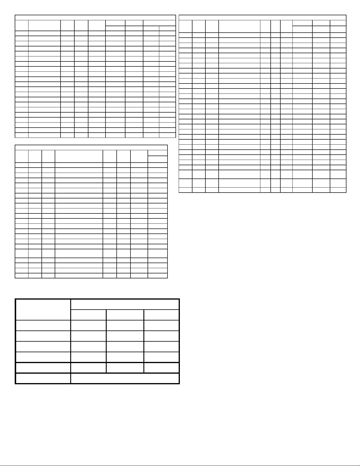
ED3703X Flash Pattern Chart
Pattern Description FPM Sync Phase SAE J595 CA Title 13 ECE 65
A, B, R, W A, B, R A, B R
1Cycle Flash (Default) - N - - - - -
2 Single Flash 75 Y A Class I Class B - -
3 Single Flash 75 Y BClass I Class B - -
4 Single Flash 120 Y A Class I - - -
5 Single Flash 120 Y BClass I - - -
6 Double Flash 75 Y A Class I Class B - -
7 Double Flash 75 Y BClass I Class B - -
8 Double Flash 120 Y A Class I - Class I Class II
9 Double Flash 120 Y BClass I - Class I Class II
10 Quad Flash 75 Y A Class I Class B - -
11 Quad Flash 75 Y BClass I Class B - -
12 Quad Flash 150 Y A Class I - - -
13 Quad Flash 150 Y BClass I - - -
14 Triple Flash 75 Y A Class I Class B - -
15 Triple Flash 75 Y BClass I Class B - -
16 Quint Flash 150 Y A Class I - - -
17 Quint Flash 150 Y BClass I - - -
18 Modulation - N - - - - -
19 Double, Triple Flash - N - - - - -
20 Single, Quad Flash - N - - - - -
21 Steady Burn - N - - - - -
Split, Single Color ED3704X, ED3705X Flash Pattern Chart
Red
Wire
White
Wire
Red &
White
Wires
Description FPM Sync Phase
SAE J595 CA Title 13 ECE 65
A, B, R, W A, B, R A, B, R
111Cycle Flash (Default) - N - - - -
2 2 2 Single Flash 75 Y A Class I Class B -
3 3 3 Single Flash 75 Y BClass I Class B -
4 4 4 Single Flash - Wig Wag 75 Y - Class I - -
5 5 5 Single Flash 120 Y A Class I - -
6 6 6 Single Flash 120 Y BClass I - -
7 7 7 Single Flash - Wig Wag 120 Y - Class I - -
8 8 8 Double Flash 75 Y A Class I Class B -
9 9 9 Double Flash 75 Y BClass I Class B -
10 10 10 Double Flash - Wig Wag 75 Y - Class I - -
11 11 11 Double Flash 120 Y A Class I - Class II
12 12 12 Double Flash 120 Y BClass I - Class II
13 13 13 Double Flash - Wig Wag 120 Y - Class I - -
14 14 14 Quad Flash 75 Y A Class I Class B -
15 15 15 Quad Flash 75 Y BClass I Class B -
16 16 16 Quad Flash - Wig Wag 75 Y - Class I - -
17 17 17 Quad Flash 150 Y A Class I - -
18 18 18 Quad Flash 150 Y BClass I - -
19 19 19 Quad Flash - Wig Wag 150 Y - Class I - -
20 20 20 Triple Flash 75 Y A Class I Class B -
21 21 21 Triple Flash 75 Y BClass I Class B -
22 22 22 Triple Flash - Wig Wag 75 Y - Class I - -
23 23 23 Quint Flash 150 Y A Class I - -
24 24 24 Quint Flash 150 Y BClass I - -
25 25 25 Quint Flash - Wig Wag 150 Y - Class I - -
26 26 26 Stead, Single Flash - Split - N - - - -
27 27 27 Modulation - Wig Wag - N - - - -
28 28 28 Double, Triple Flash - Wig
Wag
- N - - - -
29 29 29 Single, Quad Flash - Wig
Wag
- N - - - -
30 30 30 Steady Burn - N - - - -
Split, Dual Color ED3704XX, ED3705 XX Flash Pattern Chart
Red
Wire
White
Wire
Red &
White
Wires
Description FPM Sync Phase
SAE J595
A, B, R, W
111Cycle Flash (Default) - N - -
2 2 2 Single Flash - Wig Wag 75 Y A Class I
3 3 3 Single Flash - Wig Wag 75 Y BClass I
4 4 4 Single Flash - Wig Wag 120 Y A Class I
5 5 5 Single Flash - Wig Wag 120 Y BClass I
6 6 6 Double Flash - Wig Wag 75 Y A Class I
7 7 7 Double Flash - Wig Wag 75 Y BClass I
8 8 8 Double Flash - Wig Wag 120 Y A Class I
9 9 9 Double Flash - Wig Wag 120 Y BClass I
10 10 10 Quad Flash - Wig Wag 75 Y A Class I
11 11 11 Quad Flash - Wig Wag 75 Y BClass I
12 12 12 Quad Flash - Wig Wag 150 Y A Class I
13 13 13 Quad Flash - Wig Wag 150 Y BClass I
14 14 14 Triple Flash - Wig Wag 75 Y A Class I
15 15 15 Triple Flash - Wig Wag 75 Y BClass I
16 16 16 Quint Flash - Wig Wag 150 Y A Class I
17 17 17 Quint Flash - Wig Wag 150 Y BClass I
18 18 18 Steady, Single Flash -Split
Color 1 & 2
- N - -
19 19 19 Modulation - Wig Wag - N - -
20 20 20 Double, Triple Flash - Wig Wag - N - -
21 21 21 Single, Quad Flash - Wig Wag - N - -
22 22 22 Steady Burn - Color 1 & 2 - N- - --
Replacement Parts and Accessories:
Description
Part No.
ED3703 ED3704 ED3705
Black Bezel Kit EZD3703BLBZ EZD3704BLBZ EZD3705BLBZ
Chrome Bezel Kit EZD3703CHMBZ EZD3704CHMBZ EZD3705CHMBZ
Rubber Bezel Kit EZD3703RUBZ EZD3704RUBZ EZD3705RUBZ
Grill Bracket Kit EZ3703GBKT EZ3704GBKT EZ3705GBKT
L Bracket Kit EZ3703LBKT EZ3704LBKT EZ3705LBKT
License Plate Bracket Kit EZ3703LICB
Page 4 of 4
Electronics Controls Company “ECCO” (Manufacturer)
ECCO warrants that on the date of purchase, this product will conform to ECCO’s specications for this product (which are
available from ECCO upon request). This Limited Warranty extends for thirty-six (36) months from the date of purchase.
DAMAGE TO PARTS OR PRODUCTS RESULTING FROM TAMPERING, ACCIDENT, ABUSE, MISUSE, NEGLIGENCE,
UNAPPROVED MODIFICATIONS, FIRE OR OTHER HAZARD; IMPROPER INSTALLATION OR OPERATION; OR NOT
BEING MAINTAINED IN ACCORDANCE WITH THE MAINTENANCE PROCEDURES SET FORTH IN ECCO’S INSTALLA-
TION AND OPERATING INSTRUCTIONS VOIDS THIS LIMITED WARRANTY.
Exclusion of Other Warranties:
ECCO MAKES NO OTHER WARRANTIES, EXPRESSED OR IMPLIED. THE IMPLIED WARRANTIES FOR MERCHANT-
ABILITY, QUALITY OR FITNESS FOR A PARTICULAR PURPOSE, OR ARISING FROM A COURSE OF DEALING,
USAGE OR TRADE PRACTICE ARE HEREBY EXCLUDED AND SHALL NOT APPLY TO THE PRODUCT AND ARE
HEREBY DISCLAIMED, EXCEPT TO THE EXTENT PROHIBITED BY APPLICABLE LAW. ORAL STATEMENTS OR
REPRESENTATIONS ABOUT THE PRODUCT DO NOT CONSTITUTE WARRANTIES.
Remedies and Limitation of Liability:
ECCO’S SOLE LIABILITY AND BUYER’S EXCLUSIVE REMEDY IN CONTRACT, TORT (INCLUDING NEGLIGENCE), OR
UNDER ANY OTHER THEORY AGAINST ECCO REGARDING THE PRODUCT AND ITS USE SHALL BE, AT ECCO’S
DISCRETION, THE REPLACEMENT OR REPAIR OF THE PRODUCT, OR THE REFUND OF THE PURCHASE PRICE
PAID BY BUYER FOR NON-CONFORMING PRODUCT. IN NO EVENT SHALL ECCO’S LIABILITY ARISING OUT OF
THIS LIMITED WARRANTY OR ANY OTHER CLAIM RELATED TO THE ECCO’S PRODUCTS EXCEED THE AMOUNT
PAID FOR THE PRODUCT BY BUYER AT THE TIME OF THE ORIGINAL PURCHASE. IN NO EVENT SHALL ECCO
BE LIABLE FOR LOST PROFITS, THE COST OF SUBSTITUTE EQUIPMENT OR LABOR, PROPERTY DAMAGE, OR
OTHER SPECIAL, CONSEQUENTIAL, OR INCIDENTAL DAMAGES BASED UPON ANY CLAIM FOR BREACH OF CON-
TRACT, IMPROPER INSTALLATION, NEGLIGENCE, OR OTHER CLAIM, EVEN IF ECCO OR A REPRESENTATIVE OF
ECCO HAS BEEN ADVISED OF THE POSSIBILITY OF SUCH DAMAGES. ECCO SHALL HAVE NO FURTHER OBLIGA-
TION OR LIABILITY WITH RESPECT TO THE PRODUCT OR ITS SALE, OPERATION AND USE, AND ECCO NEITHER
ASSUMES NOR AUTHORIZES THE ASSUMPTION OF ANY OTHER OBLIGATION OR LIABILITY IN CONNECTION
WITH SUCH PRODUCT.
This Limited Warranty denes specic legal rights. You may have other legal rights which vary from jurisdiction to jurisdic-
tion. Some jurisdictions do not allow the exclusion or limitation of incidental or consequential damages.
833 West Diamond St
Boise, Idaho 83705
Customer Service
USA 800-635-5900
UK +44 (0)113 237 5340
AUS +61 (0)3 63322444
www.eccoesg.com
920-0549-00 Rev. D

This manual suits for next models

3

Other Ecco Lighting Equipment manuals

Ecco 21 Series User manual

Ecco

Ecco 21 Series User manual

Ecco 3800 Series User manual

Ecco

Ecco 3800 Series User manual

Ecco Stick-A-LED User manual

Ecco

Ecco Stick-A-LED User manual

Ecco ED3788 Owner's manual

Ecco

Ecco ED3788 Owner's manual

Ecco 27 Series Owner's manual

Ecco

Ecco 27 Series Owner's manual

Ecco EW3108-F Owner's manual

Ecco

Ecco EW3108-F Owner's manual

Ecco 3800 Series Owner's manual

Ecco

Ecco 3800 Series Owner's manual

Ecco Reflex 5500 Series User manual

Ecco

Ecco Reflex 5500 Series User manual

Ecco 6221000 Series User manual

Ecco

Ecco 6221000 Series User manual

Ecco ED5100 Owner's manual

Ecco

Ecco ED5100 Owner's manual

Ecco DuoBeam User manual

Ecco

Ecco DuoBeam User manual

Ecco EW5430 Series User manual

Ecco

Ecco EW5430 Series User manual

Ecco ED3974 Series Owner's manual

Ecco

Ecco ED3974 Series Owner's manual

Ecco Hide-A-LED 9014 User manual

Ecco

Ecco Hide-A-LED 9014 User manual

Ecco ED3040 Owner's manual

Ecco

Ecco ED3040 Owner's manual

Ecco ED5051VDL Series User manual

Ecco

Ecco ED5051VDL Series User manual

Ecco 5580 Series Owner's manual

Ecco

Ecco 5580 Series Owner's manual

Ecco ED3744 User manual

Ecco

Ecco ED3744 User manual

Ecco 6262 Owner's manual

Ecco

Ecco 6262 Owner's manual

Ecco Reflex 5590 Series User manual

Ecco

Ecco Reflex 5590 Series User manual

Ecco Pro Vantage 12+ Series Installation instructions

Ecco

Ecco Pro Vantage 12+ Series Installation instructions

Ecco EB7181 Series User manual

Ecco

Ecco EB7181 Series User manual

Ecco ED3022 User manual

Ecco

Ecco ED3022 User manual

Ecco 5280 Series User manual

Ecco

Ecco 5280 Series User manual

Popular Lighting Equipment manuals by other brands

Rainbow Colour Changers 8-Lite Plus Operator's manual

Rainbow Colour Changers

Rainbow Colour Changers 8-Lite Plus Operator's manual

Good Earth Lighting UC1271-WH1-09LF3-G manual

Good Earth Lighting

Good Earth Lighting UC1271-WH1-09LF3-G manual

KODA LM030007 Care & use instructions

KODA

KODA LM030007 Care & use instructions

Kody Technologies Thule T2 Classic Installation instruction

Kody Technologies

Kody Technologies Thule T2 Classic Installation instruction

Beamz BX100 instruction manual

Beamz

Beamz BX100 instruction manual

Clevertronics Nifty Lifelight Surface Mount Installation & maintenance instructions

Clevertronics

Clevertronics Nifty Lifelight Surface Mount Installation & maintenance instructions

Simon LEDFLEX 810 quick guide

Simon

Simon LEDFLEX 810 quick guide

ML Accessories SURF236HF Installation & maintenance manual

ML Accessories

ML Accessories SURF236HF Installation & maintenance manual

Conrad 57 61 14 operating instructions

Conrad

Conrad 57 61 14 operating instructions

Datalogic LT-510 quick start guide

Datalogic

Datalogic LT-510 quick start guide

Photogenic PowerLight PL2 Series Operator's manual

Photogenic

Photogenic PowerLight PL2 Series Operator's manual

Tamlite STADIA XL Installation & operating instructions

Tamlite

Tamlite STADIA XL Installation & operating instructions

CCS LFXV Series Instruction guide

CCS

CCS LFXV Series Instruction guide

BWT SL-119-MR Instructions for installation and recommendation

BWT

BWT SL-119-MR Instructions for installation and recommendation

GEAR AID FLUX FL9010 Quick start manual

GEAR AID

GEAR AID FLUX FL9010 Quick start manual

Life 39.9TS401020C quick start guide

Life

Life 39.9TS401020C quick start guide

LCG PRO LCG-FS400L user manual

LCG

LCG PRO LCG-FS400L user manual

PROLiNK DS-3602 Quick installation guide

PROLiNK

PROLiNK DS-3602 Quick installation guide

manuals.online logo
manuals.online logoBrands
  • About & Mission
  • Contact us
  • Privacy Policy
  • Terms and Conditions

Copyright 2025 Manuals.Online. All Rights Reserved.