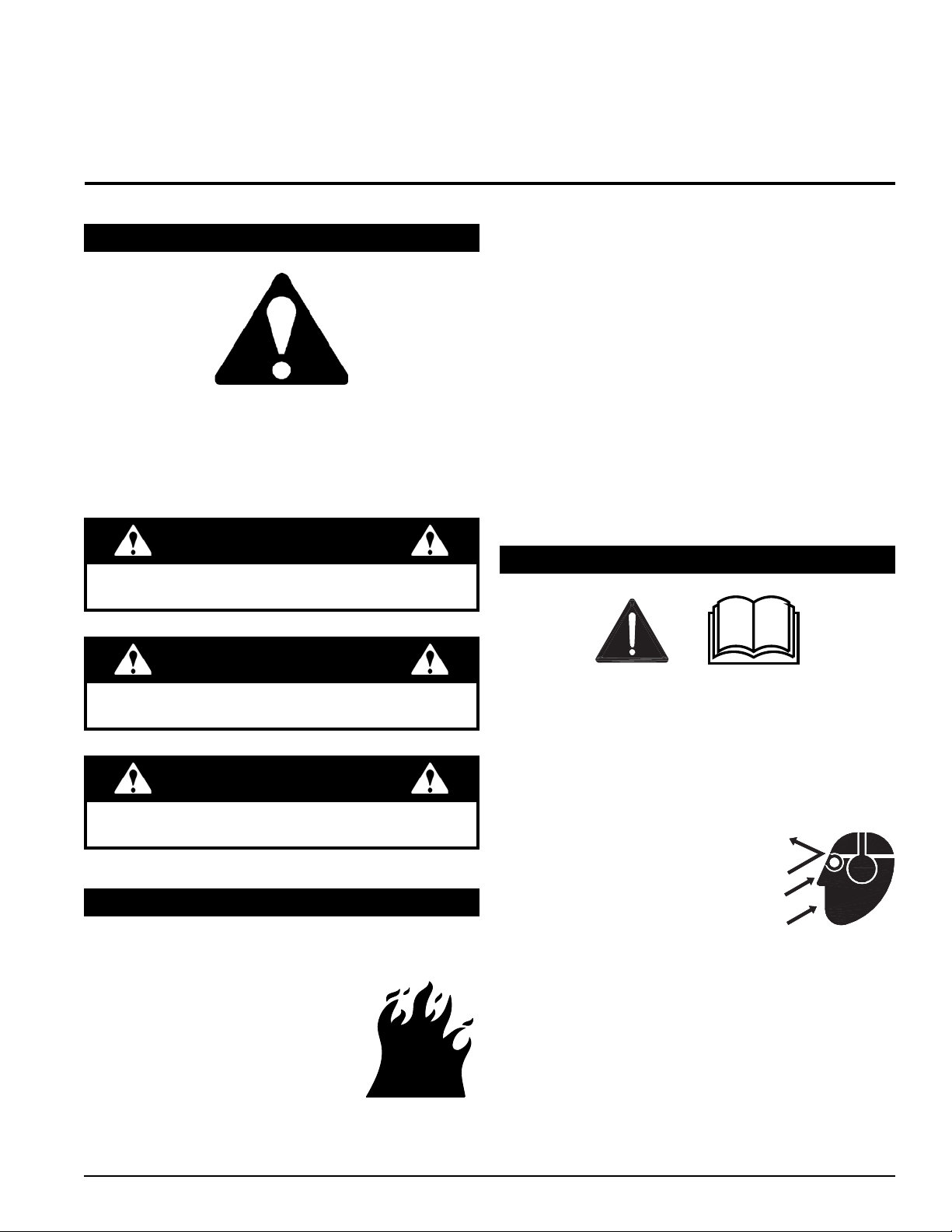
Echo BEAR CAT CH5653 User manual

OWNER'S MANUAL
ENGLISH
PN: 31602-00
Rev. 010113
Companion to 31603-00
Range: 5VJAA0000DW000001 - 5VJAA0215JW005776
CH5653 – 653cc SUBARU
5 INCH CHIPPER
www.bearcatproducts.com

Before You Begin
DEAR ECHO BEAR CAT CUSTOMER
Thank you for purchasing a ECHO Bear Cat product. The ECHO Bear Cat line is designed, tested, and manufactured
to give years of dependable performance. To keep your machine operating at peak eciency, it is necessary to adjust
it correctly and make regular inspections. The following pages will assist you in the operation and maintenance of your
machine. Please read and understand this manual before operating your machine.
If you have any questions or comments about this manual, please call us toll-free at 1.888.625.4520.
If you have any questions or problems with your machine, please call or write your local authorized ECHO Bear Cat
Dealer.
This document is based on information available at the time of its publication. ECHO Bear Cat is continually making
improvements and developing new equipment. In doing so, we reserve the right to make changes or add improvements
to our product without obligation for equipment previously sold.
PLEASE SEND US YOUR WARRANTY CARD
A warranty card is included in your owner's kit packaged with your machine. Please take the time to ll in the information
requested on the card. When you send your completed card to us, we will register your machine and start your coverage
under our limited warranty or go to bearcatproducts.com/warranty/warranty-registration/.
SERIAL NUMBER OR VIN
© 2013, CRARY INDUSTRIES, ALL RIGHTS RESERVED. PRODUCED AND PRINTED IN THE U.S.A.
IDENTIFICATION NUMBER LOCATION
Your machine will have either a serial number or vehicle
identication number (VIN). VINs are located on the left
side of the trailer frame near the hitch. They are 17-digit
numbers of the format: 5VJAA001XXWXXXXX. Serial
numbers are located on the machine body. They are
6-digit numbers.
Record your identication number in the space provided
and on the warranty registration card.
FOR MACHINE SERVICE OR PARTS:
For service assistance, contact your nearest authorized
ECHO Bear Cat dealer or the factory. For parts, contact
your authorized dealer. The parts manual for your machine
is available at http://bearcatproducts.com/main/support/
index_html. Your dealer will need to know the serial number
of your machine to provide the most ecient service. See
below for information on how to identify and record the
serial number for your machine.
FOR ENGINE SERVICE OR PARTS:
For engine service or parts, contact your nearest authorized
engine dealer. ECHO Bear Cat does not handle any parts,
repairs or warranties for engines.
ORDERING PARTS
Only genuine ECHO Bear Cat replacement parts should
be used to repair the machine. Replacement parts
manufactured by others could present safety hazards,
even though they may t on this machine. Replacement
parts are available from your ECHO Bear Cat dealer.
Provide the following when ordering parts:
The SERIAL NUMBER or VIN of your machine.
The PART NUMBER of the part.
The PART DESCRIPTION.
The QUANTITY needed.
HOW TO CONTACT ECHO BEAR CAT
ADDRESS PHONE E-MAIL HOURS
237 NW 12th Street
P.O. Box 849
West Fargo, ND 58078
888.625.4520
701.282.5520
Fax: 701.282.9522
Monday - Friday,
8 a.m. to 5 p.m.
Central Time

LIMITED WARRANTY
This warranty applies to all ECHO Bear Cat Outdoor Power Equipment manufactured by Crary Industries, Inc.
and does not include gas engine or electric powered pressure washers under the ECHO Bear Cat brand. See
ECHO Bear Cat Pressure Washer Limited Warranty for complete warranty details on those products.
Crary Industries, Inc. warrants to the original owner each new ECHO Bear Cat product to be free from defects
in material and workmanship, under normal use and service. The warranty shall extend, from date of purchase,
3 years (U.S. and Canada only (2 years outside U.S. and Canada)) for Consumer use of the product, 1 year
for Commercial applications and 6 months for Rental applications. Replacement parts and accessories are
warranted for (90) days from date of installation. Batteries for Inverters and Generators are warranted for ninety
(90) days from the date of purchase.
"Consumer" dened as: complete unit for personal, residential or non-income producing use.
"Commercial" dened as: complete unit for commercial, institutional, property management, agricultural,
horticultural or income producing use.
"Rental" dened as: complete unit for rental purposes to produce income.
*Models SC2163, SC2170 & SC3206 are classied as Consumer grade products and will not qualify for
warranty coverage if used for Commercial or Rental purposes.
The product is warranted to the original owner by either a completed warranty registration on le at Crary
Industries, Inc. and/or proof of sale. Warranty coverage begins on the date of purchase. The warranty
registration can be registered on-line by visiting http://bearcatproducts.com/warranty/warrantyregistration/ or
the paper card completed and returned to Crary Industries, Inc.
In the event of a failure, return the product, at your cost, along with proof of purchase to the selling ECHO Bear
Cat dealer. Crary Industries, Inc. will, at its option, repair or replace any parts found to be defective in material
or workmanship. Warranty on any repairs will not extend beyond the product warranty. Repair or attempted
repair by anyone other than an authorized ECHO Bear Cat dealer as well as subsequent failure or damage that
may occur as a result of that work will not be paid under this warranty. Crary Industries, Inc. does not warrant
replacement components not manufactured or sold by Crary Industries, Inc.
1. This warranty applies only to parts or components that are defective in material or workmanship.
2. This warranty does not cover normal wear items including, but not limited to: batteries, bearings, belts,
pulleys, lters, chipper blades, shredder ails or knives.
3. This warranty does not cover normal maintenance, service or adjustments.
4. This warranty does not cover depreciation or damage due to misuse, negligence, accident or improper
maintenance.
5. This warranty does not cover damage due to improper setup, installation or adjustment.
6. This warranty does not cover damage due to unauthorized modications of the product.
7. Engines are warranted by the respective engine manufacturer and are not covered by this warranty.
Crary Industries, Inc. is not liable for any property damage, personal injury or death resulting from the
unauthorized modication or alteration of an ECHO Bear Cat product or from the owner's failure to assemble,
install, maintain or operate the product in accordance with the provisions of the Owner's manual.
Crary Industries, Inc. is not liable for indirect, incidental or consequential damages or injuries including but not
limited to loss of crops, loss of prots, rental of substitute equipment or other commercial loss.
This warranty gives you specic legal rights. You may have other rights that may vary from area to area.
Crary Industries, Inc. makes no warranties, representations or promises, expressed or implied as to the
performance of its products other than those set forth in this warranty. Neither the dealer nor any other person
has any authority to make any representations, warranties or promises on behalf of Crary Industries, Inc.
or to modify the terms or limitations of this warranty in any way. Crary Industries, Inc., at its discretion, may
periodically oer limited, written enhancements to this warranty.
CRARY INDUSTRIES, INC. RESERVES THE RIGHT TO CHANGE THE DESIGN AND/OR
SPECIFICATIONS OF ITS PRODUCTS AT ANY TIME WITHOUT OBLIGATION TO PREVIOUS
PURCHASERS OF ITS PRODUCTS.
ENGLISH

TABLE OF CONTENTS
1 SAFETY .................................................................. 1
1.1 SAFETY ALERT SYMBOL ........................................ 1
1.2 FIRE HAZARD INFORMATION................................ 1
1.3 BEFORE OPERATING.............................................. 1
1.4 OPERATION SAFETY............................................... 2
1.5 BATTERY SAFETY.................................................... 3
1.6 MAINTENANCE/STORAGE SAFETY...................... 3
1.7 TOWING SAFETY ..................................................... 3
1.8 SAFETY DECALS ..................................................... 4
1.9 SAFETY DECAL LOCATIONS ................................. 5
2 ASSEMBLY............................................................. 6
2.1 ATTACH TRAILER WHEELS.................................... 6
2.2 ATTACH TRAILER HITCH ........................................ 6
2.3 ATTACH CHIPPER CHUTE ...................................... 7
2.4 ATTACH DISCHARGE TUBE ................................... 7
2.5 ADD OIL TO ENGINE................................................ 8
2.6 INSTALL BATTERY ................................................... 8
2.7 FILL THE FUEL TANK............................................... 8
3 FEATURES & CONTROLS ................................... 9
4 OPERATION......................................................... 10
4.1 STARTING ENGINE................................................ 10
4.2 STOPPING ENGINE ............................................... 10
4.3 CHIPPER OPERATION GUIDELINES .................. 10
4.4 TOWING....................................................................11
5 SERVICE & MAINTENANCE.............................. 12
5.1 MAINTENANCE SCHEDULE ................................. 12
5.2 ROTOR LOCK ......................................................... 13
5.3 RAISE/LOWER ACCESS COVER ......................... 13
5.4 CHIPPER BLADES MAINTENANCE..................... 13
5.5 REMOVING THE BLADES ..................................... 14
5.6 SHARPENING THE BLADES................................. 14
5.7 INSTALLING THE BLADES.................................... 14
5.8 SETTING CHIPPER BLADE CLEARANCE .......... 14
5.9 TRAILER MAINTENANCE TIPS ............................ 15
5.10 CLEARING A PLUGGED ROTOR........................ 15
5.11 DRIVE BELTS ........................................................ 15
5.12 REPLACING ROTOR BEARINGS ....................... 16
5.14 CHANGE OIL ......................................................... 17
5.13 LUBRICATION ....................................................... 17
6 TROUBLESHOOTING......................................... 18
7 SPECIFICATIONS ............................................... 20
7.1 BOLT TORQUE........................................................ 21
8 OPTIONS.............................................................. 22

15 INCH CHIPPER
ENGLISH
Section
1 SAFETY
Indicates an imminently hazardous situation that, if not
avoided, will result in death or serious injury.
DANGER
1.1 SAFETY ALERT SYMBOL
Indicates a potentially hazardous situation that, if not
avoided, could result in death or serious injury.
WARNING
Indicates a potentially hazardous situation that, if not
avoided, may result in minor or moderate injury.
CAUTION
The Owner/Operator's manual uses this symbol to alert
you of potential hazards. Whenever you see this symbol,
read and obey the safety message that follows it. Failure
to obey the safety message could result in personal injury,
death or property damage.
Federal, state, and local laws may prohibit the operation of
an internal combustion engine using hydrocarbon fuels on
any forest covered, brush covered or
grass covered land or on land covered
with grain, hay or other ammable
agricultural crops, without an engine
spark arrestor in continuous eective
working order.
1.2 FIRE HAZARD INFORMATION
The engine on your power equipment, like most outdoor
power equipment, is an internal combustion engine that
burns gasoline or diesel fuel (hydrocarbons). If operating
your power equipment in aected areas, it must be
equipped with a spark arrestor in continuous eective
working order. The spark arrestor must be attached to the
engine exhaust system in such a manner that ames or
heat from the system will not ignite ammable material.
Failure of the owner/operator of the equipment to comply
with federal, state, and local laws may subject him or her
to nes and/or other penalties. Contact your local re
marshal or forest service for specic information about
which regulations apply in your area.
Contact local re authorities for laws or regulations
regarding re prevention requirements.
1.3 BEFORE OPERATING
1. Read and understand this owner's manual. Be
completely familiar with the controls and the proper
use of this equipment.
2. Familiarize yourself with all of the safety and operating
decals on this equipment and on any of its attachments
or accessories.
3. Keep safety decals clean and legible. Replace missing
or illegible safety decals.
4. Obtain and wear safety glasses
and use hearing protection at all
times when operating this machine.
5. Avoid wearing loose tted clothing.
Never operate this machine while wearing clothing
with drawstrings that could wrap around or get caught
in the machine.
6. Do not operate this machine if you are under the
inuence of alcohol, medications, or substances that
can aect your vision, balance or judgement. Do not
operate if tired or ill. You must be in good health to
operate this machine safely.

25 INCH CHIPPER
SAFETY
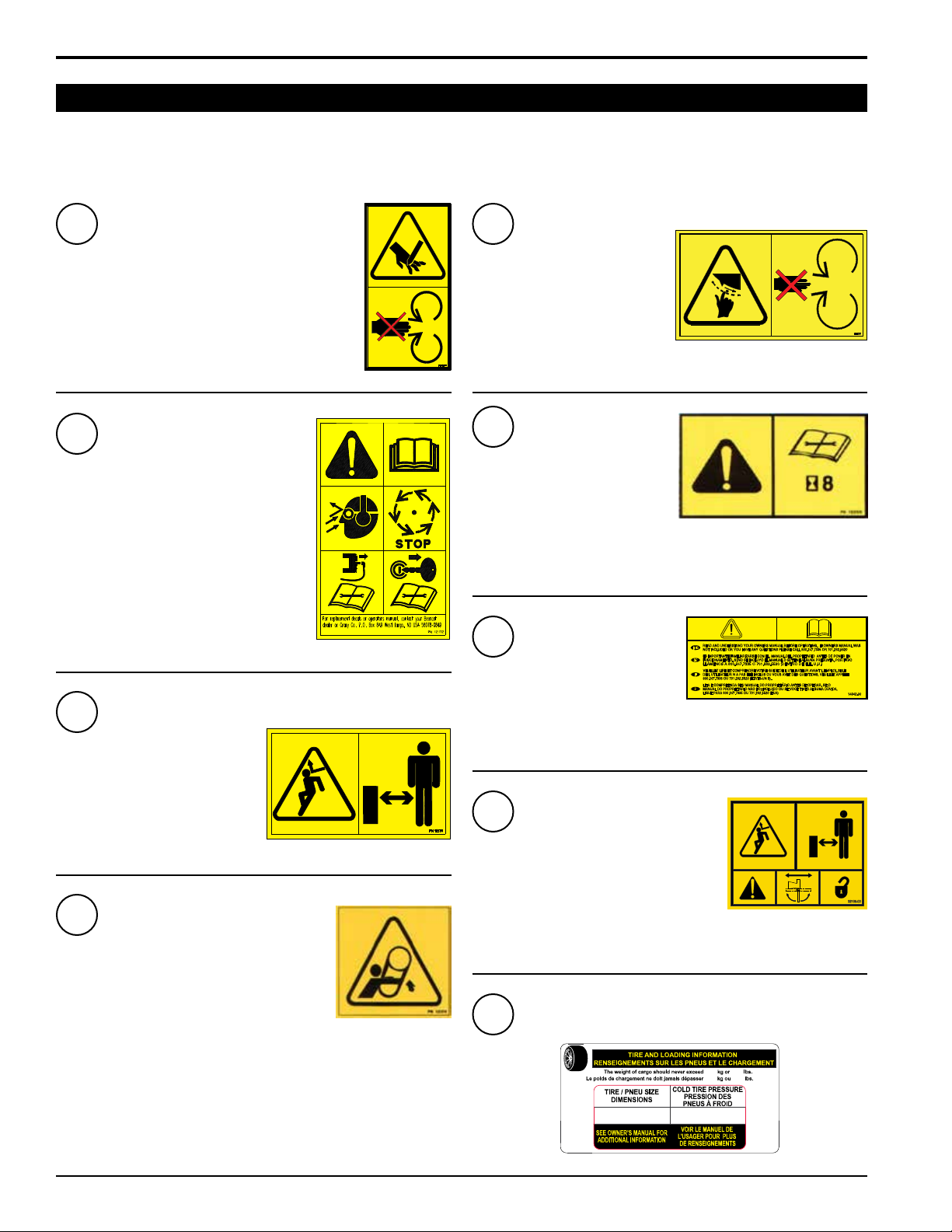
1. Always stand clear of discharge area when operating
this machine. Keep face and body away from feed
and discharge openings.
2. Keep hands and feet out of feed and discharge
openings while machine is operating to avoid serious
personal injury. Stop and allow
machine to come to a complete
stop before clearing obstructions.
3. Set up your work site so you are
not endangering trac and the
public. Take great care to provide
adequate warnings.
7. Do not operate this equipment in
the vicinity of bystanders. Keep
the area of operation clear of
all persons, particularly small
children. It is recommended that
bystanders keep at least 50 feet
(15 meters) away from the area of operation.
8. Do not allow children to operate this equipment.
9. Use only in daylight or good articial light.
10. Do not run this equipment in an enclosed area. Engine
exhaust contains carbon monoxide gas, a deadly
poison that is odorless, colorless and tasteless. Do not
operate this equipment in or near buildings, windows
or air conditioners.
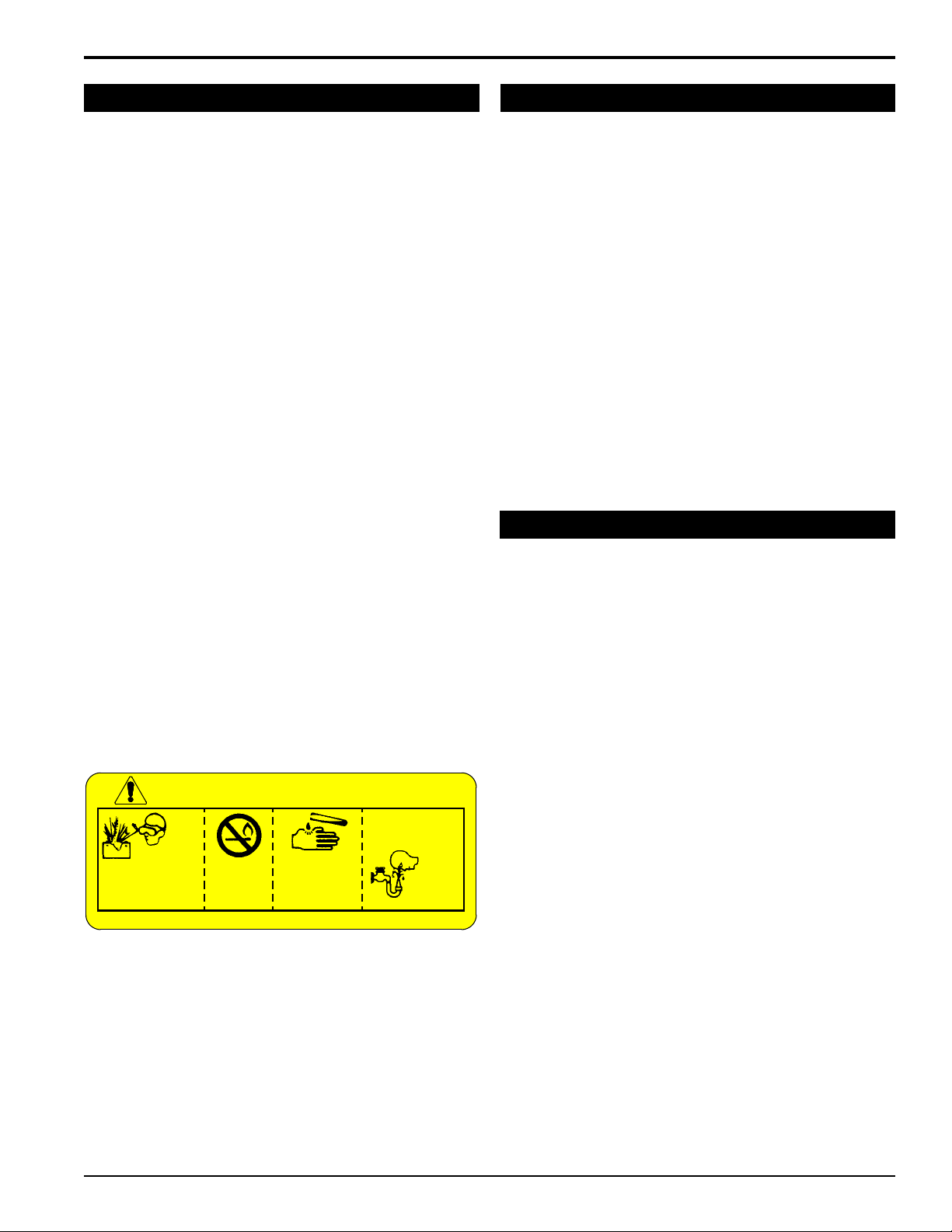
11. Always use an approved fuel container. Do not remove
gas cap or add fuel when engine is running. Add fuel
to a cool engine only.
12. Do not ll fuel tank indoors. Keep open ames, sparks,
smoking materials and other sources of combustion
away from fuel.
13. Do not operate machine without shields in place.
Failure to do so may cause serious injury or death.
14. Keep all guards, deectors, and shields in good
working condition.
15. Before inspecting or servicing any part of this machine,
shut o the machine and make sure all moving parts
have come to a complete stop. Disconnect the battery
and remove the ignition key where applicable.
16. Check that all screws, nuts, bolts, and other fasteners
are secured, tightened and in proper working condition
before starting the machine.
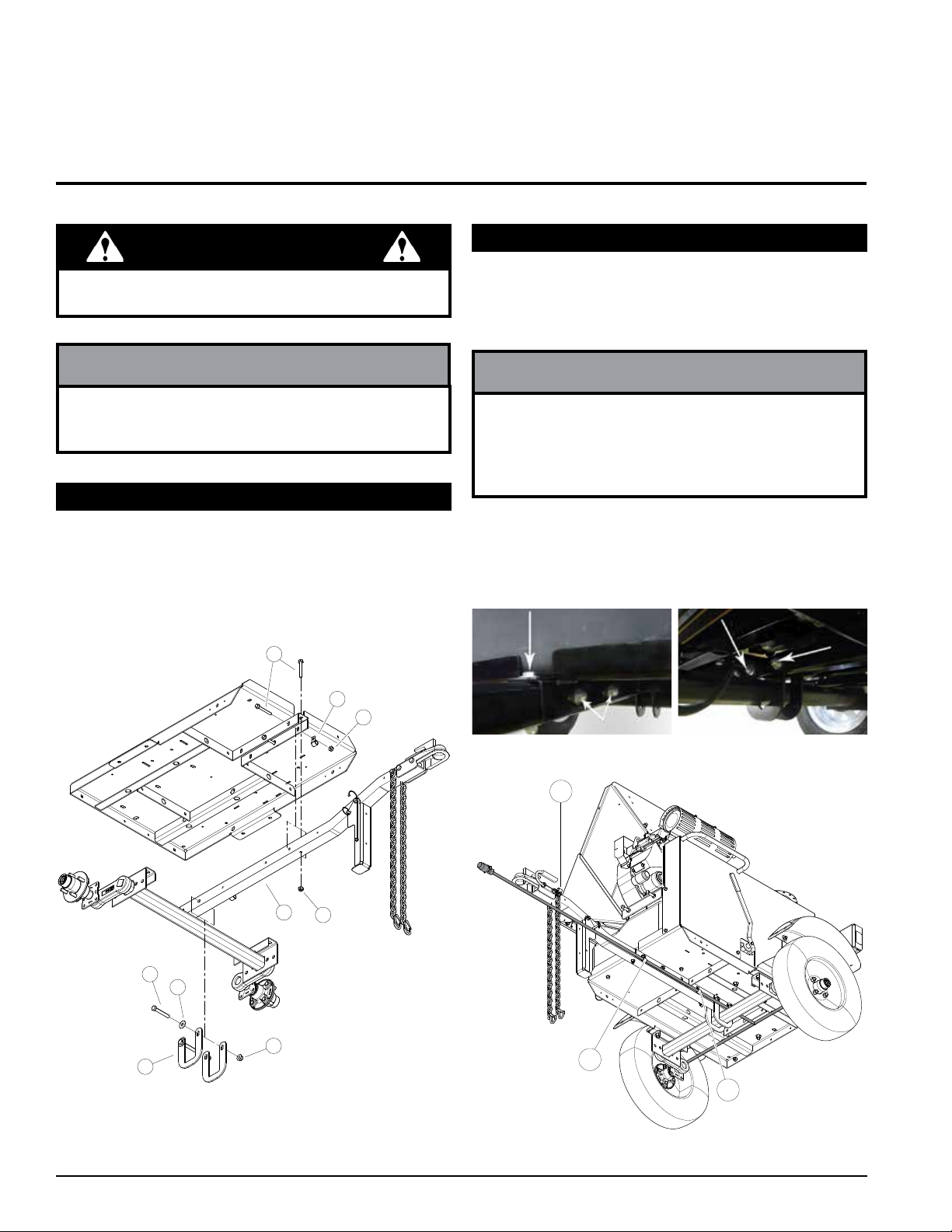
17. Do not transport or move machine while it is operating
or running.
4. Do not climb on machine when operating. Keep proper
balance and footing at all times.
5. Check cutting chamber to verify it is empty before
starting the machine.
6. The rotor will continue to rotate after being disengaged.
Shut o the machine and make sure all moving parts
have come to a complete stop before inspecting or
servicing any part of the machine. Disconnect the
battery and remove the ignition key if applicable.
7. Do not insert branches with a diameter larger than
the max chipper capacity into machine or machine
damage may occur.
8. When feeding material into machine, do not allow
metal, rocks, bottles, cans or any other foreign material
to be fed into the machine.
9. Ensure debris does not blow into trac, parked cars,
or pedestrians.
10. Keep the machine clear of debris and other
accumulations.
11. Do not allow processed material to build up in the
discharge area. This may prevent proper discharge
and can result in kickback of material through the feed
opening.
12. If the machine becomes clogged, the cutting
mechanism strikes any foreign object, or the machine
starts vibrating or making an unusual noise, shut o
machine immediately and make sure all moving parts
have come to a complete stop. Disconnect the battery
and remove the ignition key if applicable. After the
machine stops: A) Inspect for damage, B) Replace
or repair any damaged parts, and C) Check for and
tighten any loose parts.
13. On electric start models, disconnect cables from
battery before doing any inspection or service.
Remove key.
14. Check blade bolts for proper torque after every 8 hours
of operation. Check blades and rotate or resharpen
daily or as required to keep blades sharp. Failure to do
so may cause poor performance, damage or personal
injury and will void the machine warranty.
1.4 OPERATION SAFETY

35 INCH CHIPPER
ENGLISH
SAFETY
Improper use and care of the battery on electric start
models can result in serious personal injury or property
damage. Always observe the following safety precautions.
●Poison/Danger – Causes Severe Burns. The battery
contains sulfuric acid. Avoid contact with skin, eyes or
clothing. Keep out of reach of children.
●ANTIDOTE – External Contact: Flush immediately
with water.
●ANTIDOTE – Internal: Drink a large amount of water
or milk. Follow with milk of magnesia, beaten egg or
vegetable oil. Call a physician immediately.
●ANTIDOTE – Eye Contact: Flush with water for 15
minutes. Get prompt medical attention.
1. The battery produces explosive gases. Keep sparks,
ame or cigarettes away. Ventilate area when charging
battery. Always wear safety goggles when working
near battery.
2. The battery contains toxic materials. Do not damage
battery case. If case is broken or damaged, avoid
contact with battery contents.
3. Neutralize acid spills with a baking soda and water
solution. Properly dispose of a damaged or worn-
out battery. Check with local authorities for proper
disposal methods.
4. Do not short circuit battery. Severe fumes and re can
result.
5. Before working with electrical wires or components,
disconnect battery ground (negative) cable rst.
Disconnect positive cable second. Reverse this order
when reconnecting battery cables.
DANGER / POISON
FLUSH EYES
IMMEDIATELY
WITH WATER
GET
MEDICAL
HELP
FAST
KEEP OUT OF THE REACH OF CHILDREN. DO NOT TIP. KEEP VENT CAPS TIGHT AND LEVEL.
SULFURIC
ACID CAN
CAUSE
BLINDNESS OR
SEVERE BURNS
NO
• SPARKS
• FLAMES
• SMOKING
SHIELD EYES
EXPLOSIVE
GASES CAN
CAUSE BLINDNESS
OR INJURY
1.5 BATTERY SAFETY
1. Before inspecting, servicing, storing, or changing
an accessory, shut o the machine and make sure
all moving parts have come to a complete stop.
Disconnect the battery and remove the ignition key
where applicable.
2. Replace any missing or unreadable safety decals.
Refer to the safety decal section for part numbers.
3. Allow machine to cool before storing in an enclosure.
4. Store the machine out of reach of children and where
fuel vapors will not reach an open ame or spark.
5. Never store this machine with fuel in the fuel tank
inside a building where fumes may be ignited by an
open ame or spark. Ignition sources can be hot water
and space heaters, furnaces, clothes dryers, stoves,
electric motors, etc.
6. Drain the fuel and dispose of it in a safe manner for
storage periods of three months or more.
1. Connect hitch safety chains. Tighten trailer hitch bolts.
Do not attempt to tow the trailer if the vehicle is not
equipped with a 2" (50 mm) ball.
2. Do not exceed the maximum towing speed indicated
on tire sidewall. Inate tires to manufacturer's
specications as stated on the tire sidewall.
3. Optimum towing performance can be achieved by
maintaining a horizontal trailer hitch.
4. Check wheel lug bolts periodically to ensure they are
tight and secure.
5. Make sure the jack stand and the rear stabilizer
(where applicable) on the trailer are in the UP position
during towing. Place the jack stand on a level surface
and secure it in the DOWN position before using.
6. Never allow passengers to ride on the machine.
7. If applicable, shut o fuel supply when towing.
8. Towing laws may vary in dierent countries/regions/
states. It is recommended that you contact your local
motor vehicle department for any special regulations
that pertain to towing and know the laws of any
country/region/state you travel through.
1.6 MAINTENANCE/STORAGE SAFETY
1.7 TOWING SAFETY

45 INCH CHIPPER
SAFETY
1.8 SAFETY DECALS
Keep hands and feet out of inlet and discharge
openings while machine is operating to avoid serious
personal injury. Stop and allow machine to come to a
complete stop before clearing obstructions.
Read and understand this owner/operators
manual. Be completely familiar with the
controls and the proper use of this equipment
Obtain and wear safety glasses and use
hearing protection at all times when operating
this machine.
Before inspecting or servicing any part of this
machine, shut o power source, remove the
key, disconnect spark plug wire from spark
plug and make sure all moving parts have
come to a complete stop.
Do not operate this equipment in the
vicinity of bystanders. Do not allow
children to operate this equipment.
Always stand clear of discharge area
when operating this machine. Keep
face and body away from discharge
areas.
Do not operate machine without shields in place.
Failure to do so may cause serious injury or death.
Check blade bolts for proper torque
after every 8 hours of operation.
Check blades and rotate or
resharpen daily or as required to
keep blades sharp. Refer to owners
manual for instructions. Failure to do
so may cause poor performance, damage or personal injury and will void
the machine warranty.
Read and understand you owners manual before operating. If owners
manual was not included or you have any questions, please call
800.247.7335 or 701.282.5520 (U.S.A.).
Do not operate this equipment in the vicinity
of bystanders. Do not allow children to
operate this equipment. Always stand clear
of discharge area when operating this
machine. Keep face and body away from
discharge areas. Rotate the discharge tube
over the hitch before towing and lock securely in place.
See Section 1.9 for decal locations. Familiarize yourself with all of the safety and operating decals on the machine
and the associated hazards. See the engine owner's manual or contact the engine manufacturer for engine safety
instructions and decals.
Keep hands and feet out of inlet and
discharge openings while machine
is operating to avoid serious
personal injury. Stop and allow
machine to come to a complete stop
before clearing obstructions.
23 50
5.30-12 550 kPa, 80 psi
1
6
2
7
3
8
4
9
5
PN 12169
PN 12172
PN 12173
PN 12174
PN 12175
PN 14942-00
PN 32109-00
PN 12250
PN 32156-00

55 INCH CHIPPER
ENGLISH
SAFETY
10 PN 32327-00 ENG. & FR.
(32339-00 ESP. & PORT.)
11 PN 32328-00 ENG. & FR.
(32340-00 ESP. & PORT.)
12 PN 32330-00 ENG. & FR.
(32342-00 ESP. & PORT.)
13 PN 32332-00 ENG. & FR.
(32341-00 ESP. & PORT.)
*Decals 10-13 not for CE compliant machines.
1.9 SAFETY DECAL LOCATIONS
The numbers below correspond to the decals in Section 1.8. Make certain that all safety and operating decals on this
machine are kept clean and in good condition. Decals that need replacement must be applied to their original locations.
5
4*
2
3
8
7
9
1
10 11
13
12
6
7
6
*Decal located under shield

65 INCH CHIPPER
Section
2 ASSEMBLY
1. Hold one wheel to a hub and align the wheel lug holes
with the hub lug studs.
2. Thread the lug nuts on the hub studs and tighten to 75
ft-lbs. Follow a star pattern when tightening lug nuts.
3. Repeat for the remaining wheel.
2.1 ATTACH TRAILER WHEELS
Figure 2.1, Trailer Hitch Assembly (CE Compliant Shown)
1
2
2
3
4
5
6
7
8
If any bolts or nuts are dropped in the machine, be sure
to remove them before starting the machine.
WARNING
1. First, attach the hitch pole assembly (8) to the hitch
channel in the trailer deck bottom with three 3/8 x 3"
bolts (1) and nylock nuts (2). (See Figure 2.1.)
2. Next, place the two hitch plates (3) over the axle and
attach to hitch pole using two 1/2 x 3-1/4" bolts (4),
washers (5) (CE compliant model only) and nylock
nuts (7) as shown in Figures 2.1 and 2.2.
2.2 ATTACH TRAILER HITCH
Axle, wheel and hitch assemblies for some models
are supplied by the distributor and may vary from the
illustrations shown in this manual.
NOTE
Three coated clamps (6) will be used for wiring harness
mounting and routing (Figures 2.1 and 2.3) purposes.
Place wiring harness in clamps before securing the
clamps in place on the bolts. See Figures 2.1 and 2.3
for clamp locations.
NOTE
Figure 2.2, Hitch Pole Assembly Bolt Locations
Figure 2.3, Wire Harness Routing (CE Compliant Shown)
6
6
6

75 INCH CHIPPER
ENGLISH
ASSEMBLY
1. Attach one clamping ring (1) and one spacer ring (2)
to discharge tube base (3) using three 3/8 x 1-1/4"
bolts (4) and nylock nuts (5). Tighten leaving 1/16"
gap to assist in mounting to ange. See Figure 2.5.
2. Slide the tube onto the mounting ange on the
chipper frame. The discharge clamp (1) should slide
underneath the lip of the ange. Tighten the bolts and
nuts to secure it.
3. Install the second half of the spacer (2) and clamp ring
(1) on the discharge tube with 3/8 x 1-1/4" bolts (4)
and nylock nuts (5).
4. Attach lanyard with discharge pin (11) as shown in
Figure 2.6.
5. Lubricate the chute by applying grease to the grease
zerk at the base of the chute. Rotate the chute and
apply grease until the chute rotates freely.
Keep nuts as tight as possible while allowing the
discharge tube to freely turn.
NOTE
Figure 2.7, Attach Discharge Deector
7
8
9
10
11
12
13
6. Rotate the tube 360 degrees and lock it in place with
the lock pin to make sure it is mounted correctly.
7. Attach the discharge deector (7) to the discharge
tube. Connect the deector with two 5/16 x 1-1/4" bolts
(8) through the lower hole in the discharge tube. Run
these bolts through the inside of the tube, 3/8" washer
(12), deector, 5/16" washer (13), and then knob (9).
8. Finish bolting the deector to the tube with two 5/16
x 1" bolts (10) through the end hole in the discharge
tube and secure with 5/16 washers and nylock nuts
(11).
Figure 2.5, Attach Clamp Ring and Spacer
1
2
3
4
5
Figure 2.6, Attach Discharge Tube
1
2
3
4
5
6
2.3 ATTACH CHIPPER CHUTE
1. Use a support or hoist to hold the chipper chute in
place on the chipper frame.
2. Mount the chute to the chipper housing using six 3/8 x
1" carriage bolts and nylock nuts.
Figure 2.4, Attach Chipper Chute
2.4 ATTACH DISCHARGE TUBE

85 INCH CHIPPER
ASSEMBLY
To avoid sparks and a possible explosion or re due
to a short circuit, do not touch the positive (+) battery
terminal and any surrounding metal with tools, jewelry
or other metal objects. When installing battery cables,
connect the positive (+) cable rst and the negative (-)
cable last.
WARNING
Gasoline and diesel fuels are highly
ammable and their vapors are
explosive. To prevent personal injury or
property damage:
Store fuel only in approved containers,
in well ventilated, unoccupied buildings,
away from sparks or ames. A container
with a capacity of 2 gallons or less with
a pouring spout is recommended. Do
not ll the fuel tank while the engine is hot or running,
since spilled fuel could ignite if it comes in contact with
hot parts or sparks from ignition. Do not start the engine
near spilled fuel. Never use fuel as a cleaning agent.
DO NOT MIX OIL WITH FUEL.
WARNING
Use only those types of fuels that are recommended in
your engine owner's manual.
To add fuel:
1. Stop engine, wait for all parts to stop moving and
disconnect spark plug wire. Remove key from key
switch. Allow the engine and muer to cool for at least
three minutes.
2. Clean area around fuel ll cap and remove cap.
3. Using a clean funnel, ll fuel tank to 1/2" below bottom
of ller neck to provide space for any fuel expansion.
Install fuel ll cap securely and wipe up any spilled
gasoline.
Check the oil level and, if needed, ll the engine crankcase
with the type and amount of oil specied in the engine
owner’s manual.
You will need to purchase a battery. Choose a battery
that meets or exceeds the engine manufacturer’s
specications. Consult your engine owner’s manual or
authorized dealer for specication details.
To install the battery:
1. Open the battery box and insert battery into the battery
box.
2. Attach the positive (red) battery cable from the engine
to the positive (+) battery terminal.
3. Attach the negative (black) battery cable from the
engine to the negative (-) battery terminal.
4. Secure the cover on the battery box with the strap.
2.5 ADD OIL TO ENGINE
2.6 INSTALL BATTERY
2.7 FILL THE FUEL TANK
Figure 2.8, Battery Location
BATTERY BOX

95 INCH CHIPPER
ENGLISH
Section
3 FEATURES & CONTROLS
1
2
3
4
5
6
Understanding how your machine works will help you achieve the best results when using your chipper. The following
descriptions dene the features and controls of your machine.
REFER TO ENGINE OWNER'S MANUAL FOR FURTHER ENGINE OPERATING INSTRUCTIONS.
1. TRAILER HITCH
Always use 2 inch (50mm) ball and safety
chains.
2. JACK STAND
Always have in UP position and clear from
ground when moving. When in use, place
in DOWN position on a level surface.
3. BELT GUARD
Never remove guards when in use.
4. DISCHARGE TUBE
Chipped materials exit through the
rotatable discharge chute.
5. CHIPPER CHUTE
Feed materials to be chipped through the
chipper chute.
6. BELT ENGAGEMENT LEVER
When the pedal is depressed, the drive
belt is disengaged. When the pedal
is released, the drive belt is engaged.
Depress pedal to start engine.
1. ENGINE THROTTLE
Changes engine speed. Refer to
engine manual for further engine
operating instructions.
2. ENGINE CHOKE
Use when starting a cold engine. Pull
to ON position when starting. Push
lever to OFF position when engine is
running.
3. KEY SWITCH
Turn to start engine. Do not crank
starter for more than ten seconds or
damage could result.

10 5 INCH CHIPPER
Section
4 OPERATION
Move machine to a clear, level area outdoors before
starting. Do not operate in the vicinity of bystanders.
Make sure cutting chamber is empty before starting.
WARNING
Before operating your machine, be sure you read and
understand all safety, controls and operating instructions
in this owner's manual and on your machine. Failure to
follow these instructions can result in serious injury or
property damage.
WARNING
As with any other piece of outdoor equipment, getting the
feel for how your machine operates and getting to know
the best techniques for particular jobs are important to
overall good performance.
CHIPPING OPERATION
The chipping operation takes place on the front of the
machine, where hardened steel chipper blades are
mounted on a rotating rotor assembly. Material fed into
the chipper chute is sliced into small chips and propelled
out through a discharge tube.
4.1 STARTING ENGINE
1. Before starting, check levels of engine oil and fuel.
2. Place the throttle control midway between slow and
fast positions.
3. Move the choke lever to the ON position. When
restarting a warm engine after a recent shut down, it
may not be necessary to use a full choke. If the engine
fails to start, move the lever to OPEN or partial choke.
4. Move lever to START position.
4.2 STOPPING ENGINE
1. Move throttle to slowest position.
2. Allow motor to idle for 1 minute.
3. Turn engine switch to OFF position.
4. Allow machine to come to a complete stop.
5. Turn the key to the START position. Release the key
as soon as the engine starts. Do not crank engine for
more than 10 seconds.
6. Move choke lever to OPEN position.
7. Once engine is running and no choke is needed,
slowly engage lever into the CHIPPING position. This
will engage the chipping disc.
8. If the engine kills when engaging the belt, either adjust
choke or increase engine RPM.
Do not crank the engine continuously for more than 10
seconds. If the engine does not start, allow a 60 second
cool down period between starting attempts. Failure to
follow these guidelines can damage the starter motor.
Do not jump start engine.
IMPORTANT
The heavy rotor will continue to turn for some time after
the engine or tractor has been shut o. You can tell
that the rotor has stopped when no noise or machine
vibration is present. Inserting a branch into the chipper
chute to contact the blades will slow the rotor and
shorten stopping time.
NOTE
Read and follow all safety instructions in this manual.
Failure to operate the machine in accordance with
the safety instructions MAY RESULT IN PERSONAL
INJURY!
WARNING
4.3 CHIPPER OPERATION GUIDELINES
The machine chips a variety of materials into a more
readily decomposed or handled condition. The following
guidelines will help you get started.
1. Run unit at full operating speed before starting to
chip material.
2. Limbs fed in to the chipper chute must be 5 inches
(12.7 cm) in diameter or less. Trim side branches
that cannot be bent enough to feed into the chipper
chute. Hold small diameter branches together in a
bundle and feed in simultaneously.

115 INCH CHIPPER
ENGLISH
OPERATION
3. Exclude pieces of metal, rocks, bottles, cans, and
other foreign objects when feeding material into the
machine.
4. Feed brush from the side of the chipper chute,
rather than from the front. Step aside to avoid being
hit by the brush moving into the chipper.
5. Place limb, butt end rst, into the chipper chute
until it contacts the chipper blades. The actual feed
rate of the limb into the chipper will depend on the type
of material fed and sharpness of the cutting blades.
6. If the engine slows to where it may stall, stop
feeding material and allow the engine to recover.
Feed material more evenly.
●Never lean over the chipper chute to push objects
into the cutting device. Use a push stick or brush
paddle.
●Never use shovels or forks to feed brush. They can
cause extensive damage if they contact the blades.
In addition, metal pieces can be ejected from the
chipper chute and cause serious injury or death.
●Never feed brush into the chute with your feet.
●Never use hands or feet to clear materials that
build up in the chute.
CAUTION
●Obtain and wear safety glasses at all times when
operating the machine.
● Do not wear loose tting clothing.
●The operator should always wear heavy boots,
gloves, pants and a long-sleeved shirt.
●Use common sense and practice safety to protect
yourself from branches, sharp objects, and other
harmful objects.
CAUTION
4.4 TOWING
4.4.1 ATTACHING
1. Rotate the discharge tube to face the opposite
direction of the towing vehicle before towing.
2. Raise rear stabilizer.
3. Raise the extension tray to an upright position before
towing the machine. Secure with the spring-loaded
latch located near the top of the tray.
4. Open the coupler latch.
5. Raise the trailer hitch until the coupler is above the
height of the hitch ball on the towing vehicle.
6. Align the coupler over the hitch ball and lower the
trailer hitch until the coupler fully engages the hitch
ball.
7. Close the coupler latch securing the coupler to the
hitch ball.
8. Install the hitch pin through the coupler latch.
9. Cross the safety chains under the hitch and connect
to towing vehicle.
10. Connect the wire harness to the tow vehicle.
11. Raise the jack stand and rotate 90 degrees.
Optimum towing performance can be achieved by
maintaining a horizontal trailer hitch.
NOTE
7. If the chipper jams, remove the branch and rotate it
before reinserting it into the chute. Alternately insert
and retract the limb or insert continuously at a rate that
will not kill the engine.
8. Do not use the engagement lever to clear a
plugged rotor. This may cause belt damage. Refer
to the instructions for clearing a plugged rotor in the
Service and Maintenance section.
9. Alternate greener material with dry material to
lubricate the chipping blades for longer life and better
performance. Chipping dead, dry material will create
heat and dull the chipping blades quickly.
10. Sharpen the chipping blades periodically. Check
the sharpness of the blades every 5-15 hours. Refer to
the Service and Maintenance section for sharpening
instructions.
4.4.2 DETACHING
1. Unhook the safety chains from the towing vehicle.
Latch safety chains to the hitch to prevent them from
interfering with chipping.
2. Disconnect the wire harness from tow vehicle.
3. Remove the hitch pin from the coupler latch.
4. Unlatch the coupler. Disconnect the hitch coupler from
the hitch ball. Rotate jack stand 90 degrees. Raise
chipper to clear hitch ball.
5. Move the hitch of the chipper away from the hitch
ball. Raise or lower jack stand to level the chipper for
operation.
6. Lower rear stabilizer.

12 5 INCH CHIPPER
Section
5 SERVICE & MAINTENANCE
The items listed in this service and maintenance schedule are to be checked, and if necessary, corrective action taken.
This schedule is designed for units operating under normal conditions. If the unit is operating in adverse or severe
conditions, it may be necessary for the items to be checked and serviced more frequently.
SEE ENGINE OWNER'S MANUAL FOR FURTHER ENGINE MAINTENANCE AND TROUBLESHOOTING
INFORMATION.
SERVICE AND MAINTENANCE SCHEDULE
FREQUENCY
COMPONENT MAINTENANCE
REQUIRED
REFER TO ENGINE
OPERATOR'S MANUAL
BEFORE
EACH
USE
EVERY 8
HOURS
EVERY
25
HOURS
EVERY
50
HOURS
EVERY
YEAR
Air cleaner Check and clean (1) ●
Air intake Clean (1) ●
Engine oil Change (1) ●
Fuel filter Replace ●
Spark plug Check condition and gap ●
Engine oil Check/fill ●
Fuel tank Check/fill ●
All internal and external
nuts and bolts Check tightness ●
Tire pressure Check ●
Battery connections Check ●
Chipper anvil Check clearance and
re-torque to 75 ft-lbs (2) ●
Chipper blades Check sharpness and
re-torque to 25 ft-lbs (2) ●
Entire machine Clean ●
Drive belt Check ●
Belt tension Check ●
Belt/pulley alignment Check ●
Grease zerks Lube ●
Wheel bearings Check and repack ●
(1) Perform more frequently under extremely dusty conditions.
(2) Perform more frequently when chipping dry or dirty wood.
As the Limited Warranty states, failure by the Owner to perform normal maintenance will void the machine's warranty. The aggressive,
high-speed nature of chipping REQUIRES THE OWNER TO PERFORM THE ABOVE LISTED NORMAL MAINTENANCE. Special
consideration to maintain and re-torque the CHIPPER ANVIL, CHIPPER BLADES, AND ALL INTERNAL AND EXTERNAL NUTS AND
BOLTS is the sole responsibility of the Owner. Failure by the Owner to do so shall be cause for denial of warranty.
5.1 MAINTENANCE SCHEDULE

135 INCH CHIPPER
ENGLISH
SERVICE & MAINTENANCE
WARNING
BEFORE INSPECTING OR SERVICING ANY PART OF THIS MACHINE, SHUT OFF POWER SOURCE AND MAKE SURE ALL
MOVING PARTS HAVE COME TO A COMPLETE STOP.
5.2 ROTOR LOCK
Follow the steps below to install the rotor lock:
1. There is a hole in the shaft cap, the rotor shaft and
a matching hole in the bracket mounted to the rotor
bearing.
2. Rotate the rotor assembly until the hole on the rotor
shaft lines up with the holes in the rotor shaft cap and
bracket.
3. Install pin into the rotor shaft cap, bracket and shaft.
4. Remove pin when service and/or maintenance is
completed.
The rotor assembly has a lock mechanism. When
working on the rotor assembly, use the lock mechanism
at all times.
WARNING
Crack greater
than 1/8"
Broken
corner
Nick greater
than 1/8"
Chipper rotor
Chipping slot
Chipper rotor
Chipping slot
New blade Blade is too
short, must
be replaced
Figure 5.1, Rotor Lock
The chipper blades will eventually become dull, making
chipping dicult and adding extra strain on the machine.
CHECK THE SHARPNESS OF THE BLADES EVERY
5-15 HOURS OF OPERATION AND SHARPEN AS
NEEDED.
Your blades need to be sharpened if:
●Machine vibrates severely when material is fed into
the chipper.
●Chips discharge unevenly or have stringy tails,
especially when chipping green branches.
Before you sharpen the chipping blades, check for
permanent damage. Replace the blade if:
●There are cracks, broken corners or nicks greater
than 1/8" (see below).
●The base of the cutting edge is worn or has been
re-sharpened so that it no longer extends past the
chipping slot (see below).
Follow the steps below to raise or lower the access cover:
1. Rotate the discharge tube so it is parallel to the access
cover.
2. To raise the access cover, remove the two 3/8 x 1-1/4"
bolts and nuts that secure the cover to the chipper
housing.
3. Lower the access cover and secure to the chipper
housing using two 3/8 x 1-1/4" bolts and nuts.
5.3 RAISE/LOWER ACCESS COVER
5.4 CHIPPER BLADES MAINTENANCE

14 5 INCH CHIPPER
SERVICE & MAINTENANCE
WARNING
BEFORE INSPECTING OR SERVICING ANY PART OF THIS MACHINE, SHUT OFF POWER SOURCE AND MAKE SURE ALL
MOVING PARTS HAVE COME TO A COMPLETE STOP.
Figure 5.3, Chipping Anvil Location
The blades can be ground on a bench grinder or by a
professional.
1. Never sharpen or grind the mounting surfaces of
the blades. This will cause the edge to roll and the
blade will be damaged, resulting in poor chipping
performance.
2. Regrind the angled edge of the chipping blades to 45
degrees (Figure 5.2). Make sure some type of xture
is used to correctly hold the blade at the proper angle.
3. Be careful when grinding so that the blade does
not become overheated and change color. This will
remove the heat-treated properties.
4. Use short grinding times and cool with water or some
type of liquid coolant.
1. Install the rotor lock (Section 5.2). The rotor is now
restrained for installing the blades.
2. Place a blade on the rotor and attach using original
hardware. Torque the bolts to 25 ft-lbs (34 Nm).
Repeat for the remaining blade.
3. Lower the access cover and secure to the chipper
housing using two 3/8" retaining bolts.
4. Remove rotor lock.
45°
.25
Mounting Surface
(DO NOT GRIND)
Mounting Surface
(DO NOT GRIND)
Sharpened
Surface
Sharpened
Surface
Figure 5.2, Chipper Blade Surfaces
The chipping blades should clear the anvil by 1/16" to 1/8".
Check the clearance every 8 hours of operation and adjust
if needed. The chipping anvil is reversible. All four sides of
the anvil can be used for chipping.
1. Remove the two 3/8" retaining bolts securing the
access cover to the main frame assembly.
2. Open access cover to allow access to rotor. Rotate
the rotor so that the bolts holding the chipper blades
are accessible.
3. Install the rotor lock (Section 5.2). The rotor is now
restrained for removing the blades. To access the
remaining blades, remove pin and reposition rotor.
Return pin to the rotor lock hole.
4. Remove the two bolts that hold the blade to the
rotor. The hardware can be reused. Repeat for the
remaining blade.
5. The blades have two edges and can be reversed one
time before sharpening.
Chipping blades are sharp! Use caution when working
on machine to avoid injury.
WARNING
5. Remove an equal amount o each blade to maintain
rotor balance.
6. Small imperfections such as nicks and burrs on
the at side of the blade will not aect the chipping
performance of the machine.
7. For blades that have been repeatedly sharpened,
ensure that the sharpened surface extends past
the chipping slot opening. If it does not extend past
the opening, the blades should be replaced (see
Section 5.4).
5.5 REMOVING THE BLADES
5.6 SHARPENING THE BLADES
5.7 INSTALLING THE BLADES
5.8 SETTING CHIPPER BLADE
CLEARANCE

155 INCH CHIPPER
ENGLISH
SERVICE & MAINTENANCE
WARNING
BEFORE INSPECTING OR SERVICING ANY PART OF THIS MACHINE, SHUT OFF POWER SOURCE AND MAKE SURE ALL
MOVING PARTS HAVE COME TO A COMPLETE STOP.
1. Shut o engine and allow all moving parts to come to
a complete stop.
2. Remove the retaining bolts holding the access cover
to the main frame assembly and lift up access cover.
3. Clean the debris out of the chipping rotor. Turn the
rotor by hand to be sure it is free to rotate.
4. Close rotor access cover and replace bolts.
5. Start engine and engage drive belt to resume
operation.
1. Check wheel bolt torque monthly.
2. Check air pressure in tires monthly.
3. Check and repack wheel bearings with grease every
12 months.
4. When towing, always connect the safety chains. Make
sure trailer hitch bolts are tight.
5. Check trailer lights periodically.
1/16-1/8"
ANVIL
ANVIL
SPACER
ROTOR
CHIPPER
BLADE
1/2" BOLT
Figure 5.4, Chipper Blade/Anvil Clearance
To adjust the chipping anvil:
1. Lift rotor access cover and expose rotor. Loosen the
two 1/2" bolts that hold the chipper anvil to the frame.
2. Measure the amount of clearance between chipping
blade and chipping anvil from inside of housing.
3. Adjust inward or outward to desired measurement.
4. Tighten bolts on chipping anvil to 75 ft-lbs. Make
sure all blades clear the anvil by 1/16" to 1/8" before
operating.
If the chipping anvil edge is damaged or worn unevenly,
remove the two bolts holding the anvil and use one of the
other three edges. Adjust for correct measurement.
5.9 TRAILER MAINTENANCE TIPS
5.10 CLEARING A PLUGGED ROTOR
Check the condition of the drive belt annually or after
every 25 hours of operating, whichever comes rst. If the
belt is cracked, frayed, or worn, replace it. To replace or
adjust drive belt, proceed as follows:
1. Shut o engine and disconnect spark plugs.
2. Remove belt guard.
3. Remove belt guides on the engine.
4. Take the tension o the drive belt by moving the belt
engagement handle to the start postion and remove
the belt idler pulley assembly.
5. If more drive belt slack is necessary to remove the belt,
loosen the front and rear bolts located on the engine
mounting plate (see below), along with the two engine
tie bolts located under the belt shield. See Figure 5.6
5.11 DRIVE BELTS
Figure 5.5, Belt Engagement Lever

16 5 INCH CHIPPER
SERVICE & MAINTENANCE
WARNING
BEFORE INSPECTING OR SERVICING ANY PART OF THIS MACHINE, SHUT OFF POWER SOURCE AND MAKE SURE ALL
MOVING PARTS HAVE COME TO A COMPLETE STOP.
6. Then remove the drive belt from pulleys.
7. Install the new belt on pulleys. Slide engine back into
place and tighten bolts to proper torque. Install the
belt idler assembly.
8. Check pulley alignment with a straight edge and
adjust if needed.
9. Check belt tension and adjust if needed. The belt
deection at the center of the belt should be 7/16"
when a 20 lb. load is placed against it (see Figure 5.6).
10. Move the engagement lever to the engaged position
and install the belt guides so you have a 1/8 of
clearance.
11. Reinstall belt guard.
12. Move the engagement pedal back to the start position,
start engine, engage drive belt slowly, and test unit.
Readjust pulleys if needed.
Figure 5.7, Drive Belt and Pulleys
Figure 5.6, Engine Plate Adjustment Bolts
5.12 REPLACING ROTOR BEARINGS
1. Remove the 3/8" retaining bolts holding access cover
to main frame assembly. Tilt access cover over to
allow rotor access.
2. Remove the belt guard.
3. Remove belt guides on the engine.
4. Take the tension o the drive belt by moving the belt
engagement to the START position, and remove the
belt idler pulley assembly.
5. You may have to do this step to gain more slack in the
belt for removal by loosening the engine plate bolts,
also the bolts just to right of the pulley on the engine tie
will have to be loosened. Then slide the engine toward
the housing by loosening the engine adjustment bolts
just below the starter.
6. Then remove drive belt from pulleys. Remove the
bushing by removing the three capscrews in the
bushing and putting them in the drilled holes. Tighten
the screws evenly and progressively in rotation to
separate the sheave and bushing.
7. Remove the set screw on the bushing.
8. Bu the shaft with emery cloth to remove the indent
from the setscrews and any rust on the shaft.
9. Slide the bushing and sheave o the rotor shaft.
10. Remove the two 1/2" bolts on each rotor bearing and
remove the roll pin from the rotor shaft.
11. Using an overhead hoist or lifting device, lift the rotor
assembly completely out of the frame. The complete
rotor assembly is 140 lbs.
12. Once the rotor assembly is out of the frame, remove
both bearings and place new bearings on shaft.
13. Replace roll pin.
14. Use the overhead hoist or lifting device to return the
complete rotor assembly to the chipper frame.
15. Install the 1/2" bolts on engine side bearing and
tighten. Install the nuts onto the other bearing and
tighten. Slide rotor over to the engine side until the roll
pin is tight against the bearing. Lock the set screws
and torque to 160 inch-lbs. Torque bearing bolts
to 75 ft-lbs. Check and adjust chipper anvil to 1/16"
clearance if needed.
Table of contents
Other Echo Chipper manuals

Echo
Echo CH611DH (76628) User manual

Echo
Echo 77412 User manual

Echo
Echo CH8540 User manual

Echo
Echo Bear Cat CH6627H User manual

Echo
Echo Bear Cat CH922DH User manual

Echo
Echo SC3206 User manual

Echo
Echo Bear Cat 76824 User manual

Echo
Echo CH8540 User manual

Echo
Echo Bear Cat 76824 Installation guide

Echo
Echo Bear Cat CH922DH User manual

Echo
Echo 74500 User manual

Echo
Echo CH5540 User manual

Echo
Echo Bear Cat CH922DH User manual

Echo
Echo Shred 'N' Vac ES-2100 User manual

Echo
Echo Bear Cat CH500H(74500) User manual

Echo
Echo Bear Car CH45342 (77412) User manual

Echo
Echo BEAR CAT CH6720H User manual

Echo
Echo Bear Cat CH922DH User manual

Echo
Echo SC5670B (75524) User manual

Echo
Echo Bear Cat 7812086 User manual