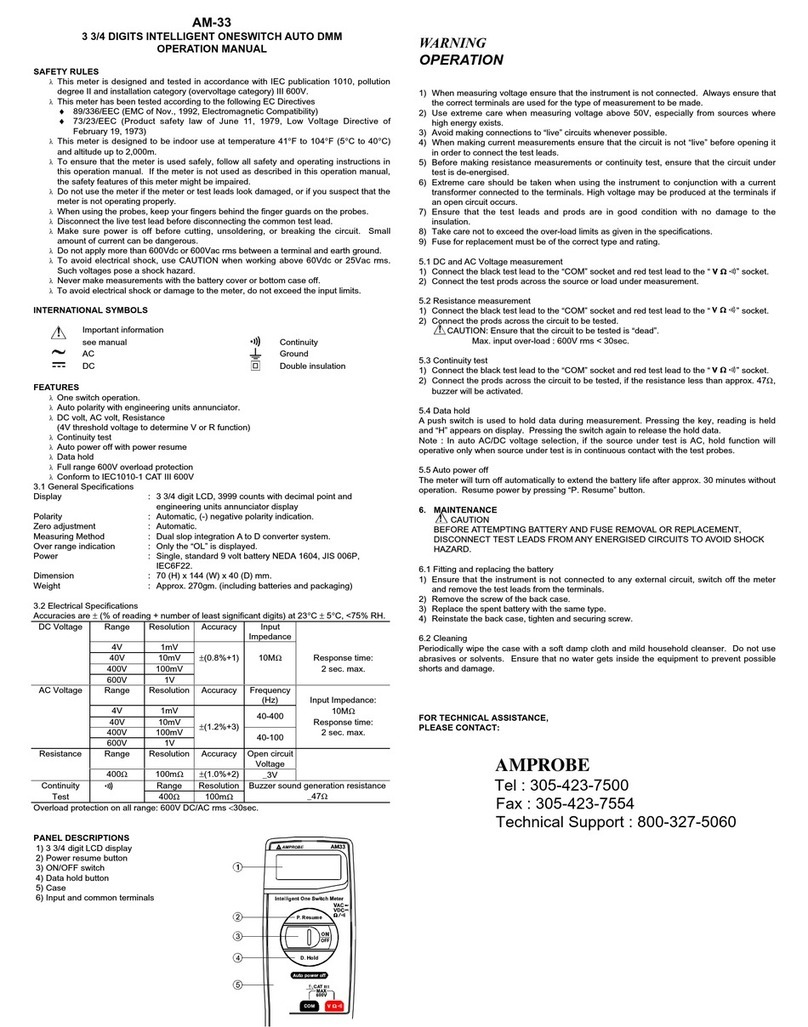
Ecolab SENSOPART FT 10 User manual

10°
10°
TECHNISCHE DATEN (TYP.) | TECHNICAL DATA (TYP.) | DONNÉES TECHNIQUES (TYP.) | DATOS TÉCNICOS (TYP.)
FT 10 -BH-
PNSL-xxx
-RH-
PNSL-xxx
-RLH-
PNSL-xxx
-RLA-
PNSL-xxx
RFx-
PNSL-xxx
B-RLFx-
PNSL-xxx
Schaltaus-
gang Q
Switching
output Q
Sortie de
commutation Q
Salida de
conmutación Q Auto-Detect
Tastweite
(TW) 1)
Scanning distance
(TW) 1)
Distance de détection
(TW) 1)
Distancia de detección
(TW) 1) 3 ... 100 mm 2 ... 70 mm 6 ... 70 mm -RF1: 2 ... 15 mm
-RF2: 2 ... 30 mm
-RF3: 2 ... 50 mm
-RLF1: 6 ... 15 mm
-RLF2: 6 ... 30 mm
Einstellbereich Adjustment range Plage de réglage Campo de ajuste 10 ... 100 mm 10 ... 70 mm 10 ... 70 mm
Messwertausgabe Measurement
value Accès à la mesure Valor de medición
de salida - - - via IO-Link - -
Lichtart Used light Type de lumière Tipo de luz LED blau l blue l
bleue l azul (EN62471)
LED rot l red l
rouge l rojo Laser, class 1
(IEC 60825-1)
LED rot l red l
rouge I rojo Laser, class
1 (IEC 60825-1)
Betriebsspannung
+UB2)
Operating voltage
+UB2)
Tension d’alimentation
+UB2)
Tensión de servicio
+UB2) 13 … 30V DC 10 … 30V DC
Leerlaufstrom I0
No-load supply
current I0
Courant hors charge I0Corriente en vacío I0≤ 20 mA ≤ 20 mA ≤ 12 mA ≤ 20 mA ≤ 12 mA
Ausgangsstrom IeOutput current IeCourant de sortie IeCorriente de salida Ie≤ 50 mA
Steuereingang
IN 3)
Control input
IN 3)
Entrée de contrôle
IN 3)
Entrada de control
IN 3)
+UB= Teach-in I keylock I
disabled4)
-UBI open = normal
function4)
+UB= Teach-in I disabled4)
-UB=
open = normal function
+ UB = N.C.
-UB = N.O.
open = N.O.
Werkseinstellung Factory setting Conguration d’origine Ajuste de fábrica max. TW, N.O. max. TW
1) Bezugsmaterial Weiß,
90 % Remission
1) Reference material white,
90 % reectance
1) Matériau de référence blanc,
90 % réexion
1) Material de referencia blanco,
90 % de reexión
=
Taste verriegelt
=
button locked
=
bouton verrouillée
=
tecla bloqueado
2) max. 10 % Restwelligkeit, innerhalb UB,
~ 50 Hz/100 Hz
2) max. residual ripple 10 %, within UB,
approx. 50 Hz/100 Hz
2) Ondulation résiduelle maxi 10 % à
l’intérieur de UB, env. 50 Hz/100 Hz
2) máx. 10 % de ondulación residual, dentro
de UB, aprox. 50 Hz/100 Hz
3) siehe Grak K, Rückseite 3) see illustration K, back 3) voir illustration K, verso 3) véase el gráco K, reverso
4) einstellbar über IO-Link, Default: Teach-in 4) adjustable via IO-Link, default: Teach-in 4) réglable par IO-Link, par défaut : teach-in 4) Ajustable por IO-Link, Por defecto: teach-in
1LED gelb
1)
Yellow LED
1) LED jaune
1) LED amarillo
1)
2Taste 2) Button 2) Bouton 2) Tecla 2)
3LED grün 3)
Green LED
3) LED verte 3) LED verde 3)
4Empfänger-
achse
Receiver
axis
Axe de
récepteur
Eje de
recepción
5Sender-
achse
Emitter axis Axe
d’émetteur
Eje de
emisión
1) Schaltausgangsanzeige | switching output indicator
acheur sortie de commutation | indicación de salida de conexión
2) Zur Tastenbedienung bei Bedarf Stift verwenden | If necessary use a pin to push
the button | Si nécessaire, utiliser un objet n pour appuyer sur la bouton | Utilice
el lápiz para el manejo de teclas cuando sea necesario
3) Betriebsspannungsanzeige | operating voltage indicator
acheur tension de service | indicación de tensión de servicio
FT 10
Reexionslichttaster mit
Hintergrundausblendung
Photoelectric diuse sensor with
background suppression
Détecteur de proximité avec
suppression d'arrière-plan
Interruptor de proximidad con
supresión de fonde
Betriebsanleitung • Operating instructions
Instructions de service • Instrucciones de servicio
068-14996 15.03.2021-00
www.sensopart.com
SICHERHEITSHINWEISE
Vor Inbetriebnahme die Betriebsanleitung lesen.
Anschluss, Montage, Einstellung und Inbetriebnahme
nur durch Fachpersonal.
Kein Sicherheitsbauteil gemäß EU-Maschinenrichtlinie
(nicht zum Schutz von Personen geeignet).
Einsatz nicht im Außenbereich.
FT 10-BH-xxx: , Risikogruppe 1; möglicherweise
gefährliche optische Strahlung (EN62471). Bei Betrieb
nicht für längere Zeit in die Lampe blicken. Kann für die
Augen schädlich sein.
FT 10-(B-)RLx-xxx: , Klasse 1;
Wellenlänge: 655 nm; Frequenz: 5 kHz; Pulsbreite:
3,2 µs; Grenzwert Puls: ≤ 2,3 mW (IEC 60825-1).
Entspricht 21 CFR 1040.10 und 1040.11 mit Ausnahme
der Abweichungen gemäß Laser Notiz Nr. 50 vom 24.
Juni 2007.
Zur Verwendung mit Typen mit Sux E4, KM3, KM4:
Gerader oder L-förmiger Stecker, Anschlusssockel aus
R/C (CYJV2).
ACHTUNG - Durch Verwendung von Bedienelementen
oder Einstellungen sowie Durchführung von Verfahren,
die nicht hier angegeben sind, kann es zum Austritt
gefährlicher Strahlung kommen.
BESTIMMUNGSGEMÄSSE VERWENDUNG
Sensor wird zum optischen berührungslosen Erfassen
eingesetzt.
ANSCHLUSS
Stecker spannungsfrei aufstecken und festschrauben.
Leitung anschließen. Es gilt das Anschlussschema
(s. Grak B).
Auto-Detect: Sensor einfach anschließen. Schaltlast
NPN oder PNP wird automatisch erkannt (manuell s.
Grak J). Wichtig: Lastspannung und Versorgungsspan-
nung von einer Versorgungsquelle. Parallelschaltung der
Sensoren mit Auto-Detect nicht möglich.
Für PNP/NPN gilt s. Grak C.
Spannung anlegen → LED grün leuchtet.
N.O. = Schließer; N.C. = Öner.
IO-Link Kommunikation → grüne LED blinkt.
Kurzschluss → beide LEDs blinken gelb.
SAFETY INSTRUCTIONS
Read operating instructions before start-up.
Connection, assembly, setting and start-up only by
trained personnel.
No safety component according to EU machinery
directives (not suited for the protection of personnel).
Not for outdoor use.
FT 10-BH-xxx: , risk group 1; potentially dangerous
optical radiation (EN62471). Do not stare at operating
lamp for a longer period. May be harmful to the eye.
FT 10-(B-)RLx-xxx: , class 1; wavelength: 655 nm;
frequency: 5 kHz; pulse duration: 3.2 µs; limit value
pulse: ≤ 2.3 mW (IEC 60825-1).
Complies with 21 CFR 1040.10 and 1040.11 except for
deviations pursuant to laser Notice No. 50 dated June
24, 2007.
For use with models with suxes E4, KM3, KM4:
Straight or L-shaped connector, connector base is made
of R/C (CYJV2).
CAUTION - Use of Controls or adjustments or perfor-
mance of procedures other than those specied herein
may result in hazardous radiation exposure.
INTENDED USE
Sensor is used for the optical non-contact detection.
CONNECTION
Insert plug voltage-free and screw it tightly.
Connect cable according to the connection diagram (see
illustration B) .
Auto-Detect: Simply connect the sensor. The switching
load NPN or PNP will be detected automatically (ma-
nually see Illustration J). Important: Load voltage and
supply voltage are from the same source. A parallel-
switching of the sensors is not possible with Auto-Detect.
For PNP/NPN see illustration C.
Apply voltage → green LED lights up.
N.O. = normally open; N.C. = normally closed.
IO-Link Communication → green LED ashes.
Short-circuit → Both LEDs are ashing yellow.
INSTRUCTIONS DE SÉCURITÉ
Lire les instructions de service avant mise en service.
Raccordement, assemblage, réglage et mise en service
ne doivent être eectués que par du personnel qualié.
Il ne s’agit pas de pièces de sécurité selon les directives
européennes en vigueur concernant les machines (inap-
propriées à la protection de personnes).
Ne pas utiliser à l’extérieur.
FT 10-BH-xxx : , risques de groupe 1 ; possibilité de
rayonnement optique dangereux (EN62471). Lors du
fonctionnement, ne pas xer la source de lumière pen-
dant une période prolongée. Peut être nocif pour les yeux.
FT 10-(B-)RLx-xxx : , classe 1 ; longueur d’onde :
655 nm ; fréquence : 5 kHz ; largeur d’impulsion : 3,2 µs ;
valeur limite impulsion : ≤ 2,3 mW (IEC 60825-1).
Correspond à 21 CFR 1040.10 et 1040.11 à l’exception
des diérences conformément à la notice du laser n° 50
du 24 juin 2007.
Pour une utilisation avec types avec suxe E4, KM3,
KM4 : Connecteur droit ou en forme de " L ", socle de
raccordement en R/C (CYJV2).
ATTENTION - L'utilisation de commandes, de réglages
ou de consignes autres que ceux spéciés présente un
risque d'exposition dangereuse aux radiations.
UTILISATION CONFORME
Le capteur est utilisé pour la détection optique sans contact.
RACCORDEMENT
Insérer le connecteur hors tension et visser.
Connecter le câble selon le schéma de raccordement
(voir illustration B).
Auto-Detect: raccorder simplement le capteur. La charge
de commutation NPN ou PNP est détectée automa-
tiquement (manuelle voir Illustration J). Important :
tension de charge et tension d’alimentation d’une source
d’alimentation. Montage parallèle des capteurs
impossible avec Auto-Detect.
Pour PNP/NPN voir illustration C.
Mettre sous tension → LED verte est allumée.
N.O. = ouverture ; N.C. = fermeture.
Communication IO-Link → LED verte clignote.
Court-circuit → Les deux LEDs clignotent en jaune.
FT 10-
BH
FT 10-
RH
FT 10-
RLH
FT 10-
RLA
FT 10-
RF
FT 10-
B-RLF
A5.2 5.2 5.5 5.5 5.2 5.5
B7.7 7.7 8 8 7.7 8
FT 10 - RH - PNSL - KM4 Example
FT 10 - xx - xx - KM3 3-pin
FT 10 - xx - xx - E4 4-pin
FT 10 - xx - xx - K4
FT 10 - xx - xx - KM4
INDICACIONES DE SEGURIDAD
Antes de la puesta en marcha, lea las instrucciones de servicio.
La conexión, el montaje, el ajuste y la puesta en marcha
deben correr a cargo únicamente de personal especializado.
No es una pieza de seguridad según la directiva de
máquinas de la UE (no es adecuada para la protección
de personas).
No utilice en el exterior.
FT 10-BH-xxx: , grupo de riesgo 1; posiblemente
radiación óptica peligrosa (EN62471). Durante el funcion-
amiento no mire la lámpara por un período prolongado de
tiempo. Puede ser nocivo para los ojos.
FT 10-(B-)RLx-xxx: , clase 1; longitud de onda:
655 nm; frecuencia: 5 kHz; amplitud de pulso: 3,2 µs;
valor límite de pulso: ≤ 2,3 mW (IEC 60825-1).
Cumple las normas 21 CFR 1040.10 y 1040.11, a excep-
ción de las desviaciones según la nota sobre láser n° 50
del 24 de junio de 2007.
Para el uso con modelos con sujo E4, KM3, KM4:
Connector recto o en forma de L, zócalo de conexión de
R/C (CYJV2).
ATENCIÓN – El uso de controles o ajustes, así como la
realización de procedimientos distintos a los especica-
dos aquí pueden provocar una exposición a la radiación
peligrosa.
USO DEBIDO
El sensor se usa para la detección óptica sin contacto.
CONEXIÓN
Conecte y atornille el conector cuando no haya tensión.
Conecte el cable. Aplique el esquema de conexión
(véase el gráco B).
Auto-Detect: Conecte el sensor. La carga de conmuta-
ción NPN o PNP se detecta automáticamente (manual
véase el gráco J)
. Importante: Tensión de carga y
tensión de alimentación de una fuente de abastecimien-
to. La conmutación paralela de los sensores con Auto-
Detect no es posible.
Para PNP/NPN véase el gráco C.
Aplique la tensión → el LED verde se enciende.
N.O. = contacto de cierre; N.C. = contacto de apertura.
Comunicación IO-Link → el LED verde se parpadea.
Corto circuito → Ambos LEDs parpadean en amarillo.
1
2
3
4
5A
B
* Bei Betriebstemperaturen über 40 °C empfehlen wir das Befestigungswinkel-Set MS F 10
* For operating temperatures exceeding 40 °C we recommend the mounting bracket set MS F 10
* Pour les températures de fonctionnement au-dessus de 40 °C nous recommandons le set d'équerre de xation MS F 10
* Para temperaturas de funcionamiento superiores a 40 °C recommendamos el juego de ángulos de jación MS F 10
MBD F 10 *
MS F 10
Data sheet and IODD IO-Link on www.sensopart.com/de/download
How-to-Videos on www.youtube.com/user/SensoPart
3-pin
Q/IO-Link 4 BK
BU3
BN1
+UB
+
-UB
-
Auto-Detect
4-pin
B
IN
Q/IO-Link
-UB
4 BK
3 BU
+
-
+U Auto-Detect
2 WH
1BN
C. SCHALTART | SWITCHING MODE | TYPE DE COMMUTATION | TIPO DE CONMUTACIÓN
PNP LED yellow
N.O. + UB
- UB
N.C. + UB
- UB
NPN LED yellow
N.C. + UB
- UB
N.O. + UB
- UB
A. MASSBILD | DIMENSIONAL DRAWING | PLAN COTES | ESQUEMA DE DIMENSIONES B. ANSCHLUSS | CONNECTION | RACCORDEMENT | CONEXIÓN
D. MONTAGE & JUSTAGE | ASSEMBLY & ADJUSTMENT | ASSEMBLAGE & AJUSTEMENT | MONTAJE & AJUSTE

Q
Q
Low
Low
High
High
Q
Q
Low
Low
High
High
1/2 1/2
Q
Q
Low
Low
High
High
1/2 1/2
Q
Q
Low
Low
High
High
1/2 1/2
Q
Q
Low
Low
High
High
Q
Q
Low
Low
High
High
3
5 6 7
Hysteresis
min. 5 mm min. 5 mmmin. 5 mm
MONTAGE (S. GRAFIK D)
Sensor an geeignetem Halter befestigen
(siehe www.sensopart.com).
JUSTAGE (S. GRAFIK D)
Sensor auf das zu erfassende Objekt ausrichten.
Vorzugsrichtung bei Tastern beachten.
EINSTELLUNG
Standard Teach-in (STI): ist für nahezu jede Anwen-
dung geeignet. Einstellung erfolgt auf das Objekt und
den Hintergrund (s. Grak F).
Object-Object Teach-in (OTI): ist geeignet für An-
wendungen bei denen der Hintergrund nicht eingelernt
werden kann. Einstellung erfolgt 2x auf das Objekt
(s. Grak G).
Dynamic Teach-in (DTI): ist geeignet den Sensor im
laufenden Prozess einzustellen, speziell bei kleinen
Objekten (s. Grak H).
FT 10-RF / FT 10-B-RLF Fix-Fokus ohne Teach-in:
Objekt in den Strahlengang bringen. Abstand von Sen-
sorvorderkante zu Objekt muss innerhalb der angegebe-
nen Tastweite (TW) liegen. Betriebsbereit.
WARTUNG
SENSOPART-Sensoren sind wartungsfrei. Es wird
empfohlen in regelmäßigen Intervallen die optischen
Flächen zu reinigen und Verschraubungen und Steck-
verbindungen zu überprüfen.
ASSEMBLY (SEE ILLUSTRATION D)
Fix sensor on suitable mounting component
(see www.sensopart.com).
ADJUSTMENT (SEE ILLUSTRATION D)
Align sensor to the target object.
Observe the preferential direction of proximity switches.
SETTING
Standard Teach-in (STI): is suited for nearly all appli-
cations. Setting is made on object and background (see
illustration F).
Object-Object Teach-in (OTI): is suited for applications
where the background cannot be taught in. Setting is
made 2x on the object. (see illustration G).
Dynamic Teach-in (DTI): is suited for setting the sensor
in the running process, particularly for small objects (see
illustration H).
FT 10-RF / FT 10-B-RLF Fixed focus without Teach-in:
Place object in the beam path. Distance between sensor
leading edge and object must be within the indicated
scanning distance (SD). Ready for operation.
MAINTENANCE
SENSOPART sensors are maintenance-free. We recom-
mend to cyclically clean the optical surfaces and check
the screw connections and plug connections.
MONTAGE (VOIR ILLUSTRATION D)
Monter le capteur sur une équerre de xation appropriée
(voir www.sensopart.com).
AJUSTEMENT (VOIR ILLUSTRATION D)
Aligner le capteur sur l’objet à détecter.
Observer la direction préférencielle des capteurs optiques
de proximité.
RÉGLAGE
Standard Teach-in (STI) : est adapté à presque toutes
les applications. Apprentissage sur l’objet puis sur
l’arrière plan (voir illustration F).
Object-Object Teach-in (OTI) : est approprié pour les
applications où l’arrière-plan ne peut être enseignée. Le
réglage est fait 2x sur l’objet (voir illustration G).
Dynamic Teach-in (DTI) : est approprié pour régler le
capteur pendant qu’il est en service, particulièrement
pour les petits objects (voir illustration H).
FT 10-RF / FT 10-B-RLF Focale xe sans Teach-in:
Placer l’objet dans le rayon de lumière. La distance
entre le bord avant du capteur et l’objet doit être dans la
portée indiquée. Prêt à l’emploi.
ENTRETIEN
Les capteurs SENSOPART ne demandent aucun
entretien. Nous recommandons de nettoyer les surfaces
optiques et vérier les raccordements et les xations
régulièrement.
MONTAJE (VÉASE EL GRÁFICO D)
Fije el sensor a un soporte adecuado
(véase www.sensopart.com).
AJUSTE (VÉASE EL GRÁFICO D)
Oriente el sensor hacia el objeto que deba detectarse.
Tenga en cuenta la dirección preferente en los interruptores.
CONFIGURACIÓN
Standard Teach-in (STI): adecuado casi para cualquier
uso. La conguración se realiza hacia el objeto y el
fondo (véase el gráco F).
Object-Object Teach-in (OTI): es adecuado para usos
en los que no se pueda entrenar el fondo. La congura-
ción se realiza 2 veces sobre el objeto (véase el gráco
G).
Dynamic Teach-in (DTI): es adecuado para congurar
el sensor con el proceso en marcha, en particular, para
objetos pequeños (véase gráco H).
FT 10-RF / FT 10-B-RLF Foco jo sin Teach-in:
Ponga el objeto dentro de la trayectoria del haz. La dis-
tancia del borde delantero del sensor al objeto tiene que
estar dentro de la distancia de detección (TW) indicada.
Listo para funcionar.
MANTENIMIENTO
Los sensores SENSOPART no necesitan manteni-
miento. Se recomienda limpiar las supercies ópticas a
intervalos regulares y comprobar las uniones atornilla-
das y conexiones.
External Teach-in → K .
External Teach-in → K .
until green & yellow LED ash at the same time only FT 10-BH: Window Q1press > 1 s
only FT 10-BH: Window Q1press > 6 s until
green LED o & yellow LED ashing
press > 3 s press > 1 s
press press ...
until green & yellow LED
ash alternately
N.O.
press > 10 s
green LED ashes
yellow LED ON
N.O.
green LED ashes
yellow LED OFF
N.C.
wait 10 s wait 10 s
1 cycle
External Teach-in → K.
K. EXTERNAL TEACH-IN
Einstellung über Steuereingang IN: Schließ- und Önungsdauer
analog den jeweiligen Angaben für die Taste.
Setting via control input IN: Closing and opening times according
to the corresponding indications for the button.
Réglage par entrée de contrôle IN : Temps de fermeture et
d’ouverture selon l’indication correspondante de la bouton.
Conguración mediante la entrada de control IN: La duración de
cierre y apertura es conforme a la indicación correspondiente de la tecla.
BN +UB
WH
Auto-Detect
until green & yellow LED
ash at the same time
press Q > 13 s
green & yellow LED ash
at the same time
wait 10 s
ok
press Q press Q press Q ...
Auto-Detect
NPN 2)
ok
green LED ashes
wait 10 s
PNP
ok
yellow LED ashes
wait 10 s
2) IO-Link ist speziziert für PNP I IO link is specied for PNP I IO-Link est spécié pour PNP I IO-link es especicado para PNP
Änderungen vorbehalten | subject to change | sous réserve de modications | salvo modicaciónwww.sensopart.com
→green and yellow LEDs
ash simultaneously
Keep button pressed > 10 s
→green and yellow LEDs
still ash simultaneously,
but faster
→sensor is set to factory
settings
both LEDs ash
Power ON
LEDs OFF
Power OFF
Press any button Press and hold any button
and Power ON
Power OFF
LEDs OFF
12345
34567
ok ok
until green & yellow LED ash at the same time until green & yellow LED ash at the same timeonly FT 10-BH: Window Q1press > 1 s
only FT 10-BH: Window Q1press > 6 s until
green LED o & yellow LED ashing
only FT 10-BH: Window Q1press > 6 s until
green LED o & yellow LED ashing
only FT 10-BH: Window Q1press > 1 s
press > 3 s press > 3 spress > 1 s press > 1 cycle
FT 10-RH / FT 10-BH / FT 10-RLH / FT 10-RLA
FT 10-RH / FT 10-BH / FT 10-RLH / FT 10-RLA
FT 10-RH / FT 10-BH / FT 10-RLH / FT 10-RLA
FT 10-RH / FT 10-BH / FT 10-RLH / FT 10-RLA
FT 10-RH / FT 10-BH / FT 10-RLH / FT 10-RLA
FT 10-RH / FT 10-BH / FT 10-RLH / FT 10-RLA
E. WERKSEINSTELLUNG | FACTORY SETTING | CONFIGURATION D'ORIGINE | AJUSTE DE FÁBRICA
Step 1: Step 2: Step 3:
F. STANDARD TEACH-IN (STI)
Step 1: Teach-in object Step 2: Teach-in background
G. OBJECT-OBJECT TEACH-IN (OTI)
Step 1: Teach-in object Step 2: Teach-in object
J UMSCHALTUNG N.O. / N.C. | SWITCHING N.O. / N.C. | INVERSION N.O. / N.C. | CONMUTACIÓN N.O. / N.C.
H. DYNAMIC TEACH-IN (DTI)
Step 1: During running process Step 2: Teach-in object during running process
L. UMSCHALTUNG AUTO-DETECT / NPN / PNP | SWITCHING AUTO-DETECT / NPN / PNP | INVERSION AUTO-DETECT / NPN / PNP | CONMUTACIÓN AUTO-DETECT / NPN / PNP
I. EINSTELL-MODI | SETTING MODES | MODES DE RÉGLAGE | MODOS DE CONFIGURACIÓN
STANDARD TEACH-IN (STI) SEE F. OBJECT-OBJECT TEACH-IN (OTI) SEE G. DYNAMIC TEACH-IN (DTI) SEE H.
Teach 1
Teach 2
Q
N.O.
Q
N.C.
Q
N.O.
Q
N.C.
1) Only FT 10-BH: Window mode
1)
ok ok
ok ok
This manual suits for next models
4
Other Ecolab Measuring Instrument manuals
Ecolab
Ecolab LMIT09/S209 User manual
Ecolab
Ecolab EMP Kompakt II User manual

Ecolab
Ecolab Nalco Water STORM Settling Rate Monitor Instruction manual
Ecolab
Ecolab HYBRID User manual
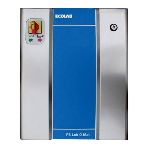
Ecolab
Ecolab Lub-O-Mat 2.5 User manual
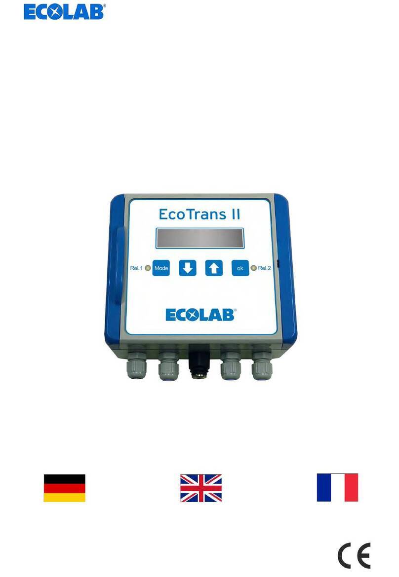
Ecolab
Ecolab EcoTrans II pH User manual
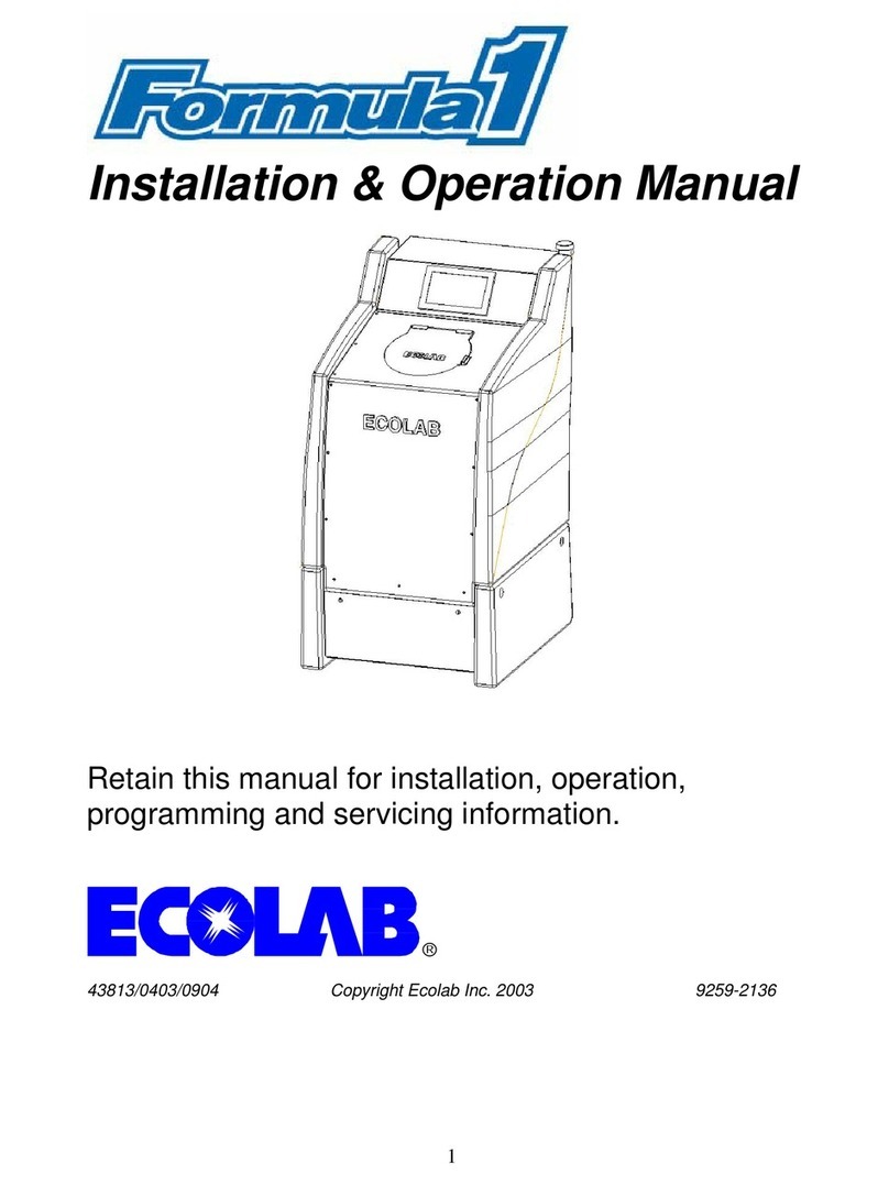
Ecolab
Ecolab Formula1 User manual
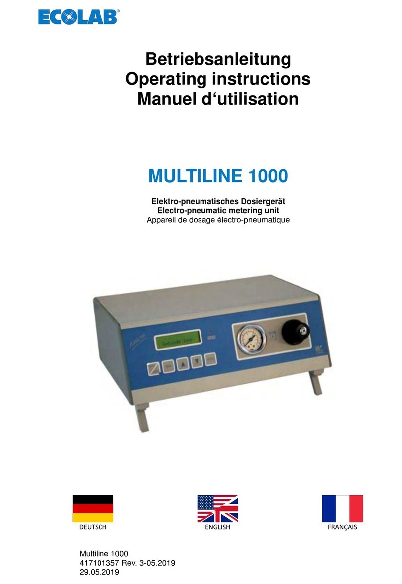
Ecolab
Ecolab MULTILINE 1000 User manual
Ecolab
Ecolab D16 User manual
Ecolab
Ecolab OGM PLUS User manual
