Ecotric Folding Fat Bike Quick start guide

WWW.ECOTRIC.COM

2
TABLE OF CONTENTS
Carton Contents------------------------------------------------------------------------------------2
Note------------------------------------------------------------------------------------------------- 3
Warning----------------------------------------------------------------------------------------------4
Assembly Instructions
Handle bar------------------------------------------------------------------------------------------ 5
Folding bike-----------------------------------------------------------------------------------------6
Front wheel----------------------------------------------------------------------------------------- 7
For seat post and pedals---------------------------------------------------------------------------8
Operating Procedures
For flash-------------------------------------------------------------------------------------------- 9
For seagull-----------------------------------------------------------------------------------------10
For fat bike ----------------------------------------------------------------------------------------11
For Tornado----------------------------------------------------------------------------------------12
Battery & Charger Care--------------------------------------------------------------------------13
Safety-----------------------------------------------------------------------------------------------14
General warning-----------------------------------------------------------------------------------15
Meter Programming & Use
800 or 810 LED-----------------------------------------------------------------------------------16
S700 LCD---------------------------------------------------------------------------------------17-18
S900 LCD---------------------------------------------------------------------------------------19-20
Troubleshooting--------------------------------------------------------------------------------- 21
Simple Maintenance Tips for your Electric Bike--------------------------------------------22
Warranty information--------------------------------------------------------------------------23-24
ECOTRIC BIKE Models------------------------------------------------------------------------25
The wiring diagram------------------------------------------------------------------------------26
RECORDING YOUR ECOTRIC BIKE INFO----------------------------------------------26
CARTON CONTENTS
(x1) Kit Box
(x2) Pedals
(x1) Owner’s user Manual
(x1) Tool Kit
(x1) Battery Charger
(x1) ECOTRIC Bike
(x1) Saddle
(x1) Lithium Ion Battery
(x2) Keys
(x1) Reflector

3
First of all, we would like to thank you for choosing the ECOTRIC electric
bike. We believe this technology, with the benefits of electric propulsion,
provides you with the perfect vehicle to increase your personal mobility.
Our brushless, electric hub motor allows you to run errands
or commute to work while saving money on gas and reducing your
environmental impact on our world. It also gives you the opportunity
to pedal if you want to get exercise along the way.
All this and it is just plain fun to ride!
If you have any concerns, questions or suggestions about the ECOTRIC
for choosing ECOTRIC.
PLEASE NOTE:
THIS MANUAL IS NOT INTENDED AS A DETAILED USER,
SERVICE, REPAIR OR MAINTENANCE MANUAL. PLEASE
SEEK ASSISTANCE FROM A QUALIFIED TECHNICIAN
FOR SERVICE, REPAIRS OR MAINTENANCE.

4
WARNING
Electric Bikes can be dangerous to use. The user or consumer assumes
all risk of personal injuries, damage, or failure of the bicycle or system and
all other losses or damages to themselves and others and to any property
arising as a result of using the bicycle.
As with all mechanical components, the bicycle is subjected to wear
and high stresses. Different materials and components may react to
wear or stress fatigue in different ways. If the design life of a component
has been exceeded, it may suddenly fail possibly causing injuries to the
rider. Any form of crack, scratches or change of coloring in highly stressed
areas indicate that the life of the component has been reached and it
should be replaced.
For replacement parts, technical information and warranty assistance,
please contact ECOTRIC BIKE at service@ecotric.com
YOUR INSURANCE POLICIES MAY NOT PROVIDE
COVERAGE FOR ACCIDENTS INVOLVING THE USE
OF THIS BICYCLE. TO DETERMINE IF COVERAGE
IS PROVIDED YOU SHOULD CONTACT YOUR
INSURANCE COMPANY OR AGENT.

5
ASSEMBLY INSTRUCTIONS
For Handle bar
Your bike has been pre-assembled and requires only a few simple steps
to get it ready for you to ride:
1. Carefully remove your bike from the carton and gently rest it in place with the
kickstand down.
2. Remove all of the inside cardboard protection and bubble wrap on the bike.
3. Please locate and set aside the kit box containing the battery charger, pedals, and
tool kit etc.
4. Place the handle bar on the stem, and tighten four bolts with 5mm hexagonal
spanner (Figure 1), Position the handlebars to your desired comfort level.
5. Once the handlebars are aligned and the top bolt is slightly secured, firmly tighten
the 2 side bolts on the stem with 6mm hexagonal spanner(Figure 3). After tightening
the 2 side bolts, firmly tighten the top bolt with 5mm hexagonal spanner(Figure 2).
After all 3 bolts have been securely fastened, make sure there is no play in the
headset.
WARNING:
Do not over tighten the stem bolt. Over tightening the stem bolt can damage the
steering system and cause loss of control.
Figure 1
Figure 2 Figure 3

6
ASSEMBLY INSTRUCTIONS
For Folding Fatbike
Guide for folding:
Battery Operation For Folding Fatbike
To remove or insert the battery
The battery is fully inserted in the battery holder, to remove the battery, turn the key
to the "Off" position and press the key to "UNLOCK" position, lift the battery vertical
from top side of the battery, and remove or insert the battery. The key switch must be
in the unlock position to slide the battery in and out.
Power on/off switch ( See Figure 1 )to turn on/off the power. Switch to "on"
position.
Charging of battery
To charge the battery, plug the charger into an AC outlet. Then plug the charger plug
into the charging port on the bike(see Figure 2).
Figure 1 Figure 2
How to fold head stem vertically.
How to fold frame.

7
ASSEMBLY INSTRUCTIONS
For Front wheel
CAUTION: Your Electric bike is equipped with a front disk brake. Be careful not to
damage the disk, caliper or brake pads when reinserting the disk into the caliper.
Never activate a disk brake’s control lever unless the disk is correctly inserted in the
caliper.
Your bicycle may be equipped with a different securing method for the front wheel
(1) With the steering fork facing forward, insert the wheel between the fork blades so
that the axle seats firmly at the top of the fork dropouts. The cam lever should be on
rider’s left side of the bicycle (fig. 4-1)
(2) While pushing the wheel firmly to the top of the slots in the fork dropouts, and at
the same time centering the wheel rim in the fork:
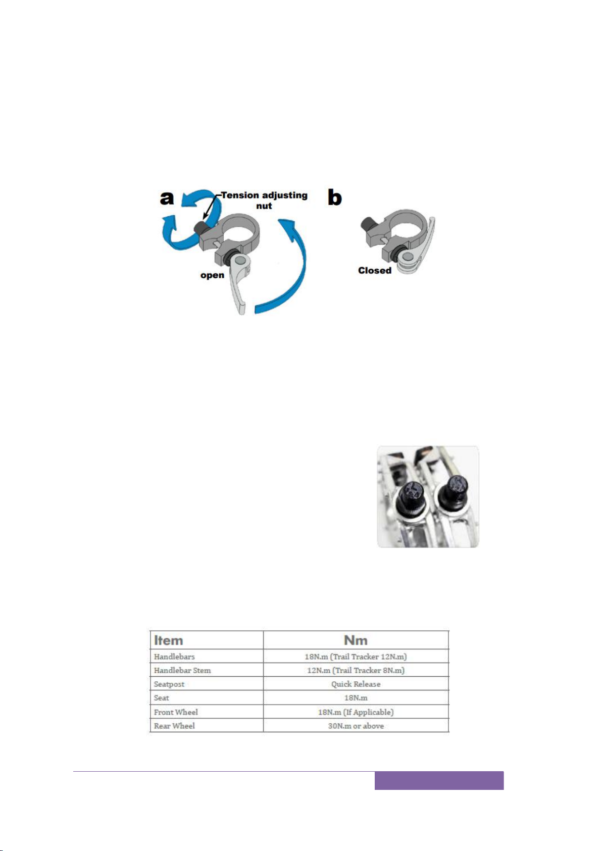
With a cam action system, move the cam lever upwards and swing it into the CLOSED
position (fig. 4-1). The lever should now be parallel to the fork blade and curved
toward the wheel. To apply enough clamping force, you should have to wrap your
fingers around the fork blade for leverage, and the lever should leave a clear imprint
in the palm of your hand.
NOTE: If, on a traditional cam action system, the lever cannot be pushed all the
way to a position parallel to the fork blade, return the lever to the OPEN
position. Then turn the tension adjusting nut counterclockwise one quarter
turn and try tightening the lever again.
WARNING: Securely clamping the wheel with a cam action retention device takes
considerable force. If you can fully close the cam lever without wrapping your fingers
around the fork blade for leverage, the lever does not leave a clear imprint in the
palm of your hand, and the serrations on the wheel fastener do not emboss the
surfaces of the dropouts, the tension is insufficient. Open the lever; turn the tension
adjusting nut clockwise a quarter turn; then try again.
Spin the wheel to make sure that it is centered in the frame and clears the brake pads;
then squeeze the brake lever and make sure that the brakes are operating correctly.
(3) Hex nuts or hex key bolts which are threaded on to or into the hub axle. (bolt-on
wheel, fig. 4-4 )
8
ASSEMBLY INSTRUCTIONS
For seat post and pedals
Make sure the seat is tight enough so that you can’t twist it out of alignment.
Pull the seat clamp handle away from the seat post and slide the seat up
or down to adjust it . Move the clamp handle inward toward the
seat post so it is held tight by the clamp.
If necessary, tighten the clamp by twisting the clamp handle clockwise while in the
unclamped position. Then, fold the handle in toward the seat post. This should
require a fair amount of force to ensure the seat post is held tight. If necessary, the
clamp can be further tightened with a 5 mm allen wrench while in the clamped
position. Make sure the seat is not set with the vertical maximum height marks above
the clamp.
Using the 15 mm wrench provided in the tool
kit, attach and tighten the pedals. PLEASE
NOTE –The pedals are marked “L”for Left
and “R”for Right. The left pedal is attached
by turning it counterclockwise and the right
pedal is tightened by turning it clockwise.
Make sure the pedals are tightly attached
to the crank arms to prevent stripping.
TORQUE SPECIFICATIONS

9
OPERATING PROCEDURES
For Flash
Removable hidden lithium batteries on each side frame, already mounted with
locks (Figure 1). The battery must be locked when riding or it may fall out. The
keys for battery locks also operate power on/off switch which is located under
the seat post (Figure 1).
Figure 1
Charging of battery
Included with your new bike is a lithium ion battery, along with a charger, which
plugs into a standard household electric receptacle. The battery may be charged while
on the bike (Figure 3) or removed (Figure 1) and charged at a location away from the
bike. The battery is easily removed by turning the key switch to the open/unlock
position.
To charge the battery, plug the charger into an AC outlet. The LED indication
light should be green showing the charger is working normally. Then plug the charger
plug (Figure 2) into the charging port on the bike (Figure 3) or removed batteries
(Figure 1) with a combination of cable divided into 2 cables.
Figure 1
Figure 2
Figure3

10
OPERATING PROCEDURES
For Seagull
To remove or insert the battery
Removable battery under the seat. Lift up the seat by loose the seat clamp(Figure 1)
to create room to insert and remove the battery, move the seat away from the bike,
turn the key to the "Off" position and press the key to "UNLOCK" position, Lift up the
hand shank on the top of the battery (Figure 2) and remove or insert the battery. The
key switch must be in the unlock position to slide the battery in and out.
Charging of battery
To charge the battery, plug the charger into an AC outlet. The LED indication
light should be green showing the charger is working normally. Then plug the charger
plug(Figure 2) into the charging port on the bike(red arrow on Figure 3).
Figure 1
Figure 2
Figure 1
Figure 2

11
OPERATING PROCEDURES
For 26’ Fat bike
To remove or insert the battery
The battery is fully inserted in the battery holder, to remove the battery, turn the key
from "off" position to "on" position( Figure 1), line up the grooves ( Figure 2)on the
top of the battery and remove or insert the battery.
Power on/off switch ( Figure 3)to turn on/off the power. Switch to on position,
the power button light turns on also.
Charging of battery
To charge the battery, plug the charger into an AC outlet. Then plug the charger plug
into the charging port on the bike(red arrow on Figure4).
.
For Folding Fatbike
To remove or insert the battery
The battery is fully inserted in the battery holder, to remove the battery, turn the key
to the "Off" position and press the key to "UNLOCK" position, lift the battery vertical
from top side of the battery, and remove or insert the battery. The key switch must be
in the unlock position to slide the battery in and out.
Power on/off switch ( See the photo on page 6 )to turn on/off the power. Switch
to "on" position.
Charging of battery
To charge the battery, plug the charger into an AC outlet. Then plug the charger plug
into the charging port on the bike(See the photo on page 6).
Figure 1
Figure 2
Figure 3
Figure 4

12
OPERATING PROCEDURES
For Tornado
To remove or insert the battery
The battery is fully inserted in the
battery holder, to remove the battery,
turn the key to the "Off" position and
press the key to "UNLOCK" position, lift
up the battery along with the holder and
remove or insert the battery. The key
switch must be in the unlock position to
slide the battery in and out.
Power on/off switch ( See the
photo )to turn on/off the power. Switch
to "on" position.
Charging of battery
To charge the battery, plug the charger into an AC outlet. Then plug the charger plug
into the charging port on the bike(see the photo).

13
BATTERY AND CHARGER CARE
The charger will charge a fully depleted battery in 5—6 hours. The indicator light on
the charger will be red when battery is charging and will turn green when fully charged.
Avoid subjecting the battery to high temperatures, such as directly
under the sun, for prolonged periods of time.
Recharge the battery before it becomes completely discharged. Completely
discharging will reduce the numbers of recharging cycles during the battery’
s life and
limit the capacity. Never store the battery in a discharged state. After much use, your
battery’s charge-holding capacity will decrease. If you find that your battery does not
hold a sufficient charge, you should contact us to order a replacement.
If the battery will not be used for an extended period of time, charge it fully and
recharge it every 2 months. Store it in a cool, dry place. Your battery is engineered
with precision for high capacity and a long, useful life. Do not use it to power other
electrical devices. Improper use of the battery will damage the battery and shorten its
useful life and may cause ire or an explosion. If you experience unusual sounds or
odors coming from the charger or the battery, unplug charger immediately and
contact customer service.
Recharge battery after every use.
•Do not disassemble or alter the battery or battery charger.
•Do not place the battery near ire or corrosive substances.
•Do not allow any liquids on or inside the battery/charger.
•Do not expose the battery/charger to extreme weather conditions.
•Do not operate the battery/charger if damaged.
•Recharge the battery only with a charger specified by the manufacturer.
•Do not use the battery/charger for any use other than its intended purpose.
•Only use the battery/charger on approved products.
Please instruct your children to keep away from the charging place.

14
SAFETY
Helmet:
Always wear an approved helmet while riding your bike and
follow the helmet manufacturer’s instructions for it, use and
care of your helmet.
It is your responsibility to familiarize yourself with the laws of
where you ride your Bike and to comply with all applicable
laws.
Mechanical Safety Check:
Check the condition of your Bike before every ride. Make sure no nuts, bolts or fixing
are loose, with particular attention to the axle nuts and handlebar stem. Make sure
the tires are correctly inflated with the recommended air pressure that is located on
the side wall of every tire. Check the brakes for proper operation. You must take your
bike in to be serviced and checked by a qualified bike mechanic before 100 miles (161
kilometers) of riding. This is a standard good practice for any new bike as cables will
stretch and components will "bed in". The service must include spoke tensioning for
both front and rear wheels.
Your First Ride:
When you buckle on your helmet and go for your first ride, be sure to pick an area
away from cars, other cyclists, obstacles or other hazards in order to become familiar
with the controls, features and performance of your new Bike.
Additional Passengers:
The Bike bikes are designed for one passenger only (excluding Tandems).DO NOT
carry any additional passengers on the front or rear of the bike.
Weight Capacity:
Bike Electric Bikes are designed with a maximum weight capacity of 220 pounds for
all models. The rear rack maximum weight capacity of a Bike (if applicable) is 25
pounds. Exceeding the maximum weight capacity can result in damage of the bike
which can lead to serious injury.
Tires & Wheels
Make sure tires are correctly inflated. Check by putting one hand on the saddle, one
on the intersection of the handlebars and stem, then bouncing your weight on the
bike while looking at tire deflection. Compare what you see with how it looks when
you know the tires are correctly inflated; and adjust if necessary. Tires in good shape?
Spin each wheel slowly and look for cuts in the tread and sidewall. Replace damaged
tires before riding the bike. Wheels true? Spin each wheel and check for brake
clearance and side-to side wobble. If a wheel wobbles side to side even slightly, or
rubs against or hits the brake pads, take the bike to a qualified bike shop to have the
wheel trued.

15
GENERAL WARNING
Like any sport, bicycling involves risk of injury and damage. By choosing to ride a
bicycle, you assume the responsibility for that risk, so you need to know —and to
practice—the rules of safe and responsible riding and of proper use and
maintenance. Proper use and maintenance of your bicycle reduces risk of injury.
Your electric bicycle is designed for use by persons 16 years old or older. Riders must
have the physical coordination, reaction time and mental capability to ride and
manage traffic, road conditions, sudden situations and also respect the laws
governing bicycle use where they ride, regardless of age. If you have an impairment
or disability such as a visual impairment, hearing impairment, physical impairment,
cognitive/language impairment, or a seizure disorder, consult your physician before
riding any bicycle.
A special note for parents
As a parent or guardian, you are responsible for the activities and safety of your child,
and that includes making sure that the bicycle is properly fitted to the child; that it is
in good repair and safe operating condition; that you and your child have learned and
understand the safe operation of the bicycle; and that you and your child have
learned, understand and obey not only the applicable local motor vehicle, bicycle and
traffic laws, but also the common sense rules of safe and responsible bicycling. As a
parent, you should read this manual, as well as review its warnings and the bicycle’s
functions and operating procedures with your child, before letting your child ride the
bicycle.
Make sure that your child always wears an approved bicycle helmet when riding;
but also make sure that your child understands that a bicycle helmet is for
bicycling only, and must be removed when not riding. A helmet must not be worn
while playing, in play areas, on playground equipment, while climbing trees, or
at any time while not riding a bicycle. Failure to follow this warning could result
in serious injury or death.
Your electric bicycle is for use by persons 16 years old and older, only. Do not let
a child younger than 16 years old ride the bicycle.

16
Meter Programming & Use
800 or 810 LED
Operations:
Press ON/FF to start the power:
Press 6km/h to have cruise 6km/h speed automatic riding without pedals
Press mode to select the pedal assistant power with pedals and throttle
(Low-Med-High)
Low=40% of max speed;
Med=75% of max speed;
High=100%of max speed
L-H is indicating the battery power
17
Meter Programming & Use
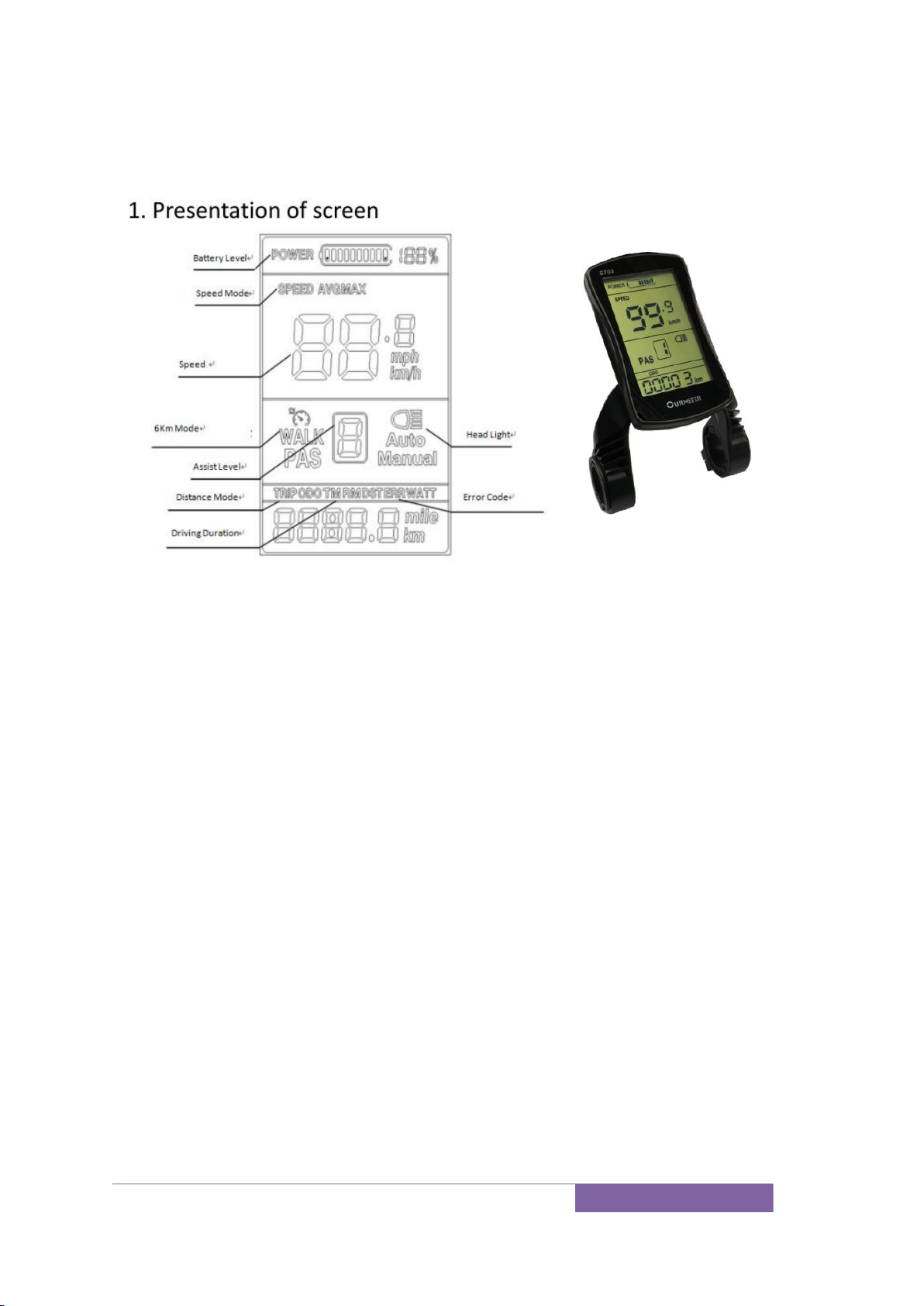
S700 LCD
1) Battery level: 5 levels, voltage interval could be customized
2) Speed:Average SPEED/MAX SPEED
3) Speed unit:Kmh/MPH
4) 6km mode
5) Assist level:actual assist level 0~5.
6) Head light icon:indicates when head light and back light are on
7) Distance:Trip/ODO
8) Driving Duration
9) Error code:“ERROR”and code when there is error
To turn the unit on, press and hold the “M” button to start the display. A long press
again “M” will switch it off. The display switches off automatically if there is no
activity for ten minutes (default).
Display setting:
Long press up and M button to shift between Max speed→Average speed
Short press M button to switch ODO/Trip/Driving Time/Error Code
Short press up or down button to change assist level, default value is level 1
Long press up button for 3 seconds turn on/off the head light when application
Long press down button to enter/quit 6km/h mode, “walk” will show up on
screen
Advanced setting
Long Press and hold the up and down button for seconds to enter the setup interface,
short press up or down button to change the value, short press M button to save
current value and switch to next parameter.

18
Backlight-P01, press up or down button to change the brightness (range is 1 to 3)
Speed unit-P02, press up or down button to change between MPH and KMH.
Voltage-P03, press up or down button to change the voltage 24v/36v/48v.Please
don’t change the default value.
Sleep time interval setting-P04. Press up or down button to change the time,
range from 0 to 60 minutes. Display will sleep and cut off power after no
operation on system for the selected time, the default value is 5 minutes.
Assist level-P05. Press up or down button to change the level between 0(max
level=3) and 1(max level=5).
Wheel size-P06. Press up or down button to change wheel size. Please don’t
change the default value.
Speed limit-P07. Short press up or down button to set the speed limit from 15 to
45km/h
Reset all parameters-P11. Long press up button 5 seconds, when displays “ssss”,
all parameters reset to default values (except for the ODO distance)
Error codes
When something goes wrong with system, an error code will flash on the display.
Check details on attached list.
The motor will stop working in the event of an error. Only when the error is gone, will
the motor work again.
Error Codes:
Error code
Definition
0
Normal
2
Short circuit protection of motor
3
Controller error
4
Throttle error
5
Motor error
8
Low battery level
9
High battery level
10
Motor hall sensor error
30
UART receive error

19
Meter Programming & Use
S900 LCD
1) Speed :Average SPEED/MAX SPEED
2) Speed unit :Kmh/MPH
3) Battery level: 5 levels, voltage interval could be customized
4) Head light icon :indicates when head light and back light are on
5) Error code :“ERROR”and code when there is error
6) Assist level :actual assist level 0~5, 0 –no assist, 1- ECO, 2,3-STD,
4,5-POWER)
7) Distance :Trip/ODO
8) 6km mode
To turn the unit on, press and hold the “M” button to start the display. A long press
again “M” will switch it off. The display switches off automatically if there is no
activity for ten minutes (default).
Display setting:
Short press M button to switch ODO/Trip.
Short press up or down button to change assist level, default value is level 1
Long press up button for 3 seconds turn on/off the head light when application
Long press down button to enter/quit 6km/h mode, “walk” will show up on
screen
Advanced setting
Long Press and hold the up and down button for seconds to enter the setup interface,
short press up or down button to change the value, short press M button to save
current value and switch to next parameter.
Backlight-P01, press up or down button to change the brightness (range is 1 to 3)
Speed unit-P02, press up or down button to change between MPH and KMH.
Voltage-P03, press up or down button to change the voltage 24v/36v/48v.Please
don’t change the default value.

20
Sleep time interval setting-P04. Press up or down button to change the time,
range from 0 to 60 minutes. Display will sleep and cut off power after no
operation on system for the selected time, the default value is 5 minutes.
Assist level-P05. Press up or down button to change the level between 0(max
level=3) and 1(max level=5) and 2(max level=9)
Wheel size-P06. Press up or down button to change wheel size. Please don’t
change the default value.
Speed limit-P07. Short press up or down button to set the speed limit from 15 to
45km/h
Reset all parameters-P11. Long press up button 5 seconds, when displays “ssss”,
all parameters reset to default values (except for the ODO distance)
Error codes
When something goes wrong with system, an error code will flash on the display.
Check details on attached list.
The motor will stop working in the event of an error. Only when the error is gone, will
the motor work again.
Error Codes:
Error code
Definition
0
Normal
2
Short circuit protection of motor
3
Controller error
4
Throttle error
5
Motor error
8
Low battery level
9
High battery level
10
Motor hall sensor error
30
UART receive error
This manual suits for next models
7
Table of contents
Other Ecotric Bicycle manuals


