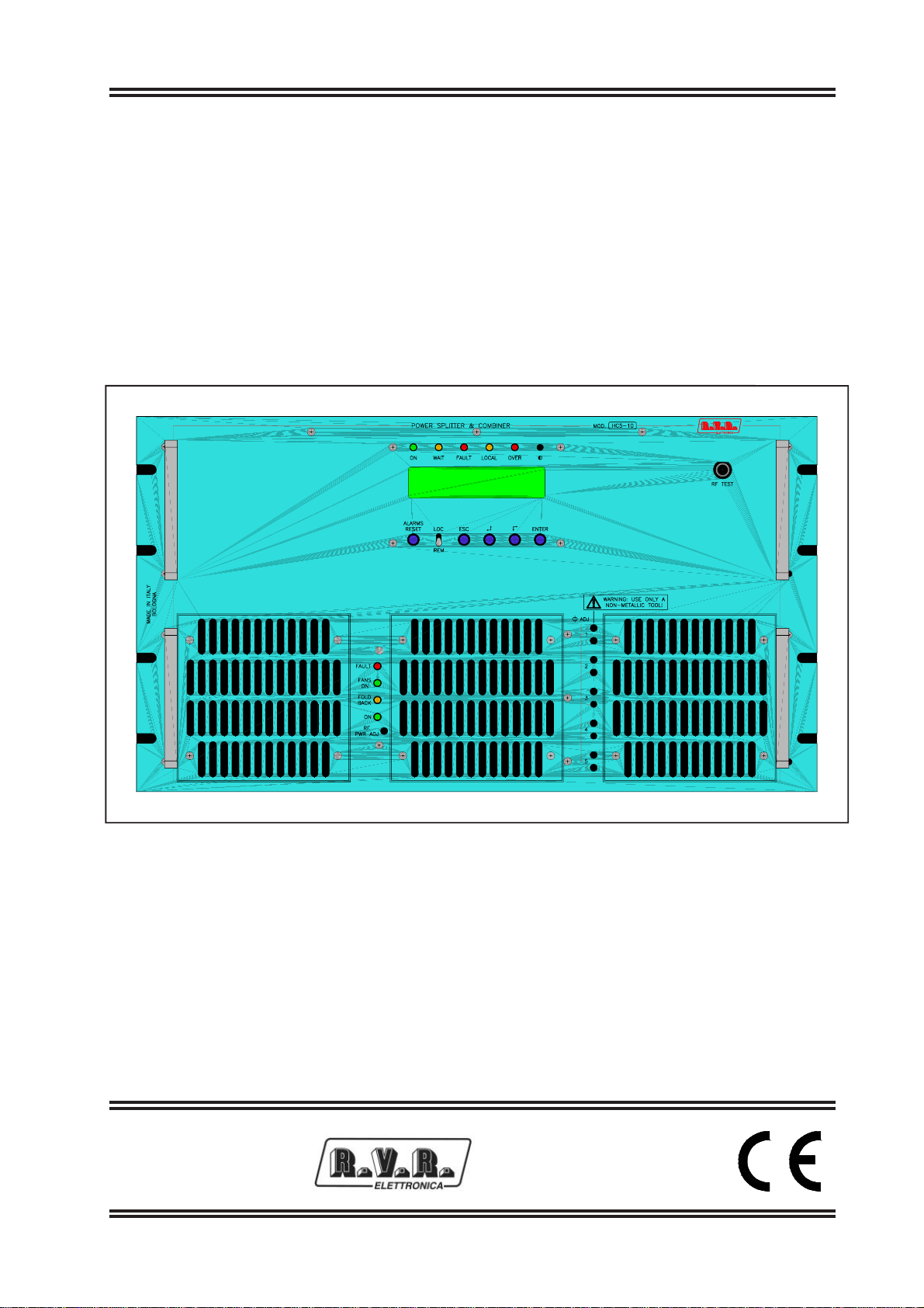
HC5-10
1 / 34UserManual Rev.1.0-26/03/04
1. Preliminary Instructions
This manual is written as a general guide for those having previous knowledge and experience with this kind of
equipment, well conscious of the risks connected with the operation of electrical equipment.
It is not intended to contain a complete statement of all safety rules which should be observed by personnel in using this
or other electronic equipment.
The installation, use and maintenance of this piece of equipment involve risks both for the personnel performing them and
for the device itself, that shall be used only by trained personnel.
R.V.R. Elettronica SpA doesn’t assume responsibility for injury or damage resulting from improper procedures or
practices by untrained/unqualified personnel in the handling of this unit.
Please observe all local codes and fire protection standards in the operations of this unit.
WARNING: always disconnect power before opening covers or removing any part of this unit. Use appropriate grounding
procedures to short out capacitors and high voltage points before servicing.
WARNING: this device can irradiate radio frequency waves, and if it’s not installed following the instructions contained
in the manual and local regulations it could generate interferences in radio communications. This is a "CLASS A"
equipment. In a residential place this equipment can cause hash. In this case can be requested to user to take the
necessary measures.
R.V.R. Elettronica SpA reserves the right to modify the design and/or the technical specifications of the product and this
manual without notice.
2. Warranty
Any product of R.V.R. Elettronica is covered by a 24 (twenty-four) month warranty.
For components like tubes for power amplifiers, the original manufacturer’s warranty applies.
R.V.R. Elettronica SpA extends to the original end-user purchaser all manufacturers warranties which are transferrable
and all claims are to be made directly to R.V.R. per indicated procedures.
Warranty shall not include:
1 Damage while the equipment is being shipped to R.V.R. for repairs;
2 Any unauthorized repair/modification;
3 Incidental/consequential damages as a result of any defect
4 Nominal non-incidental defects
5 Re-shipment costs or insurance of the unit or replacement units/parts
Any damage to the goods must be reported to the carrier in writing on the shipment receipt.
Any discrepancy or damage discovered subsequent to delivery, shall be reported to R.V.R. Elettronica within 5(five)
days from delivery date.
To claim your rights under this warranty, you shold follow this procedure
1 Contact the dealer or distributor where you purchased the unit. Describe the problem and, so that a possible easy
solution can be detected.
Dealers and Distributors are supplied with all the information about problems that may occur and usually they can
repair the unit quicker than what the manufacturer could do. Very often installing errors are discovered by dealers.