ECS G41T-MR23 User manual

Preface
Preface
Copyright
This publication, including all photographs, illustrations and software, is protected
under international copyright laws, with all rights reserved. Neither this manual, nor
any of the material contained herein, may be reproduced without written consent of
the author.
Version 1.0
Disclaimer
The information in this document is subject to change without notice. The manufac-
turer makes no representations or warranties with respect to the contents hereof and
specifically disclaims any implied warranties of merchantability or fitness for any
particular purpose. The manufacturer reserves the right to revise this publication and
to make changes from time to time in the content hereof without obligation of the
manufacturer to notify any person of such revision or changes.
TrademarkRecognition
Microsoft, MS-DOS and Windows are registered trademarks of Microsoft Corp.
MMX, Pentium, Pentium-II, Pentium-III, Celeron are registered trademarks of Intel
Corporation.
Other product names used in this manual are the properties of their respective
owners and are acknowledged.
FederalCommunicationsCommission(FCC)
This equipment has been tested and found to comply with the limits for a Class B
digital device, pursuant to Part 15 of the FCC Rules. These limits are designed to
provide reasonable protection against harmful interference in a residential installa-
tion. This equipment generates, uses, and can radiate radio frequency energy and, if
not installed and used in accordance with the instructions, may cause harmful inter-
ference to radio communications. However, there is no guarantee that interference
will not occur in a particular installation. If this equipment does cause harmful
interference to radio or television reception, which can be determined by turning the
equipment off and on, the user is encouraged to try to correct the interference by one
or more of the following measures:
• Reorient or relocate the receiving antenna
• Increase the separation between the equipment and the receiver
• Connect the equipment onto an outlet on a circuit different from that to
which the receiver is connected
• Consult the dealer or an experienced radio/TV technician for help
Shielded interconnect cables and a shielded AC power cable must be employed with
this equipment to ensure compliance with the pertinent RF emission limits govern-
ing this device. Changes or modifications not expressly approved by the system’s
manufacturer could void the user’s authority to operate the equipment.

ii
Preface
DeclarationofConformity
This device complies with part 15 of the FCC rules. Operation is subject to the
following conditions:
• This device may not cause harmful interference, and
• This device must accept any interference received, including interfer-
ence that may cause undesired operation
CanadianDepartmentofCommunications
This class B digital apparatus meets all requirements of the Canadian Interference-
causing Equipment Regulations.
Cet appareil numérique de la classe B respecte toutes les exigences du Réglement sur
le matériel brouilieur du Canada.
AbouttheManual
The manual consists of the following:
Chapter 1
Introducing the Motherboard
Chapter 2
Installing the Motherboard
Chapter 3
UsingBIOS
Chapter 4
Using the Motherboard Software
Describes features of the
motherboard.
Go to Hpage 1
Describes installation of motherboard
components.
Go to Hpage 7
Provides information on using the
BIOSSetup Utility.
Go to Hpage 29
Describes the motherboard software.
Go to Hpage 49
Chatper 5
SettingUp eJIFFY
Describes the eJIFFY setting up
Go to Hpage 53
Chatper 6
TroubleShooting
Provides basic trouble shooting tips
page 63Go to H

iii
TT
TT
TABLE OF CONTENTSABLE OF CONTENTS
ABLE OF CONTENTSABLE OF CONTENTS
ABLE OF CONTENTS
Preface i
Chapter 1 1
IntroducingtheMotherboard 1
Introduction......................................................................................1
Feature...............................................................................................2
Specifications....................................................................................5
MotherboardComponents.............................................................6
Chapter 2 77
77
7
Installing the Motherboard 7
SafetyPrecautions............................................................................7
Choosinga ComputerCase.............................................................7
Installingthe Motherboard in a Case............................................7
CheckingJumperSettings...............................................................8
Setting Jumpers...................................................................8
Checking Jumper Settings...................................................9
Jumper Settings...................................................................9
InstallingHardware........................................................................10
Installing the Processor.....................................................10
Installing Memory Modules...............................................12
Expansion Slots.................................................................18
Connecting Optional Devices............................................20
Installinga HardDiskDrive/CD-ROM/SATA HardDrive..22
ConnectingI/ODevices................................................................24
ConnectingCase Components.....................................................25
Front Panel Header...........................................................28
Chapter 3 29
UsingBIOS 29
Aboutthe SetupUtility................................................................29
The Standard Configuration..............................................29
Entering the Setup Utility....................................................29
Resetting the Default CMOS Values...................................30
UsingBIOS......................................................................................31
Standard CMOS Setup.......................................................32
Advanced Setup..................................................................34
Advanced Chipset Setup.....................................................37
Integrated Peripherals........................................................38
Power Management Setup..................................................39

iv
PCI/PnP Setup...................................................................40
PC Health Status................................................................40
Frequency/Voltage Control.................................................45
Load Default Settings.........................................................46
Supervisor Password.........................................................46
User Password...................................................................47
Save & Exit Setup................................................................47
Exit Without Saving.............................................................47
Updating the BIOS...............................................................48
Chapter 4 4949
4949
49
UsingtheMotherboardSoftware 49
AbouttheSoftwareDVD-ROM/CD-ROM.................................49
Auto-installingunder WindowsXP/Vista/7...............................49
Running Setup....................................................................50
ManualInstallation........................................................................52
UtilitySoftwareReference............................................................52
Chapter 5 5353
5353
53
SettingUpeJIFFY 53
Introduction..........................................................................................53
InstallationandBIOSSetup.................................................................54
Entering eJIFFY.............................................................................................57
Features Icons...........................................................................................58
Usage FAQ.................................................................................................59
Chapter 6 6363
6363
63
TroubleShooting 63
Startup problemsduring assembly.......................................................63
Start up problems after prolong use.................................................64
Maintenanceand care tips..................................................................64
BasicTroubleshooting Flowchart...................................................65

1
IntroducingtheMotherboard
Chapter1
IntroducingtheMotherboard
Introduction
Thank you for choosing the G41T-MR23 motherboard. This motherboard is a high
performance, enhanced function motherboard designed to support the LGA775 socket
Intel®Conroe/Presler/Wolfdale/Yorkfield processors for high-end business or per-
sonal desktop markets.
The ICH7 Southbridge supports one PCI slot which is PCI v2.3 compliant. In addi-
tion, one PCI Express x1 slot is supported, fully compliant to the PCI Express Base
Specification revision 1.0. It implements an EHCI compliant interface that provides
480 Mb/s bandwidth for eight USB 2.0 ports (four USB ports and two USB 2.0 headers
support additional four USB ports). One onboard IDE connector supports two IDE
devices in Ultra ATA100/66/33 mode. The Southbridge integrates a Serial ATA host
controller, supporting four SATA ports with maximum transfer rate up to 3.0 Gb/s
each.
The motherboard is equipped with advanced full set of I/O ports in the rear panel,
including PS/2 mouse and keyboard connectors, one VGA port, four USB ports, one
LAN port, and audio jacks for microphone, line-in and line-out.
The motherboard incorporates the Intel®G41 Northbridge (NB) and Intel®ICH7
Southbridge (SB) chipsets. The Northbridge supports a Front Side Bus (FSB) fre-
quency of 1333/1066/800 MHz using a scalable FSB Vcc_CPU. The memory con-
troller supports DDR3 memory DIMM frequencies of 1333 (OC)/1066/800; DDR2
memory DIMM frequency of 800. It supports two DDR3 sockets with up to maxi-
mum memory of 8 GB or two DDR2 sockets with up to maximum memory of 8 GB.
High resolution graphics via one PCI Express slot, intended for Graphics Interface,
is fully compliant to the PCI Express Gen 1.

2
IntroducingtheMotherboard
Feature
The motherboard uses an LGA775 type of Intel®Conroe/Presler/Wolfdale/
Yorkfield processors that carries the following features:
Processor
• Intel®Conroe/Presler/Wolfdale/Yorkfield processors
• Supports a system bus (FSB) of 1333/1066/800 MHz
• LGA775 socket for latest Intel®45nm Multi-Core processors
The Intel®G41 Northbridge (NB) and Intel®ICH7 Southbridge (SB) chipsets are
based on an innovative and scalable architecture with proven reliability and
performance.
Chipset
G41 (NB)
ICH7 (SB)
Memory
• EnhancedDMAController,interruptcontroller,andtimer
functions
• Compliant with PCI Express Base Specification, Revi-
sion 1.0a
• Compliant with PCI v2.3 specification
• Integrated SATA 3.0 Gb/s Host Controller
• Integrated USB 2.0 Host Controller supporting up to
eight USB 2.0 ports
• Integrated IDE controller supports UltraATA 100/66/33
• Supports 36-bit host bus addressing, allowing the CPU
to access the entire 64 GB of the memory address
space
• 2 GB/s point-to-point Direct Media Interface (DMI) to
ICH7 (1 GB/s each direction)
• Supports 2-GB, 1-Gb, 512 Mb DDR2 DRAM technolo-
gies for x8 and x16 devices
• Supports 1-Gb, 512 Mb DDR3 DRAM technologies for
x8 and x16 devices
• One, 16-lane (x16) PCI Express port intended for ex-
ternal device attach, fully compatible to the PCI Ex-
press Gen 1
• An integrated graphics device (IGD) delivering cost
competitive 3D, 2D and video capabilities
• Microsoft DX10 and 128MB share memory are sup-
ported
• Supports DDR3 1333 (OC)/1066/800 DDR3 SDRAM with Dual-channel
architecture
• Supports DDR2 800 DDR SDRAM with Dual-channel architecture
• Accommodates two unbuffered DIMMs
• 2 x 240-pin DDR3 DIMM sockets support up to 8 GB
• 2 x 240-pin DDR2 DIMM sockets support up to 8 GB
This board supports CPU up to 95W TDP.
Users pleased be noted that DDR3 & DDR2 memory modules can not be
installed at the same time.

3
IntroducingtheMotherboard
Onboard LAN (optional)
• Supports PCI ExpressTM 1.1
• Integrated 10/100/1000 transceiver
• Wake-On-LAN (WOL) and remote wake-up support
Audio
This motherboard may support either of the following Audio chipsets:
• 5.1 Channel High DefinitionAudio Codec
• Exceeds Microsoft Windows Logo Program (WLP) Requirements
• ADCs support 44.1K/48K/88.2K/96K/192KHz sample rate
• Power Support: Digital: 3.3V; Analog: 5.0V
The motherboard comes with the following expansion options:
• One PCI Express x16 slot for Graphic Interface
• One PCI Express x1 slot
• One 32-bit PCI v2.3 compliant slot
• One IDE connector that supports two IDE devices
• Four 7-pin SATA connectors
Expansion Options
• Two PS/2 ports for mouse and keyboard
• One VGA port
• Four USB ports
• One LAN port
• Audio jacks for microphone, line-in and line-out
The motherboard has a full set of I/O ports and connectors:
Integrated I/O
• Supports PCI ExpressTM 1.1
• Integrated 10/100 transceiver
• Wake-On-LAN (WOL) and remote wake-up support

4
IntroducingtheMotherboard
1.Some hardware specifications and software items are subject to change
without prior notice.
2.Due to chipset limitation, we recommend that motherboard be oper-
ated in the ambiance between 0 and 50°C.
The firmware can also be used to set parameters for different processor clock
speeds.
• Power management
• Wake-up alarms
• CPUparameters
• CPUandmemorytiming
BIOS Firmware
This motherboard uses AMI BIOS that enables users to configure many system
features including the following:

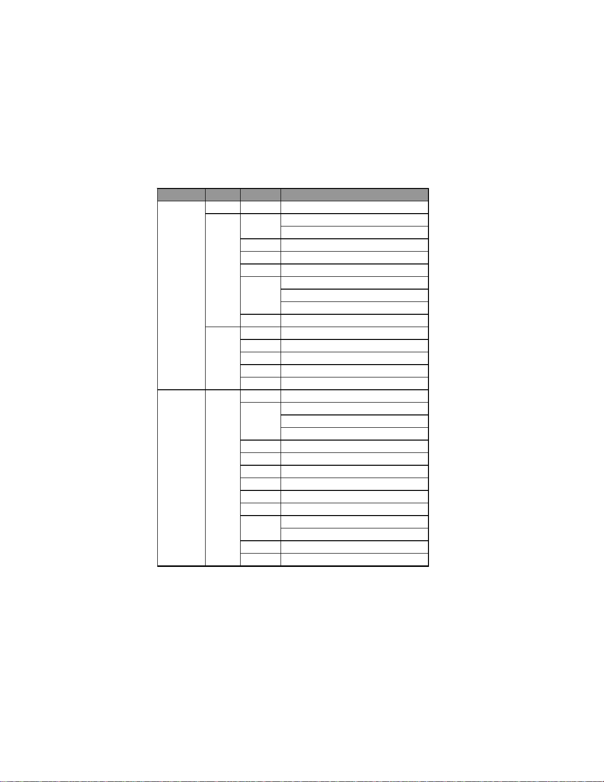
5
IntroducingtheMotherboard
• Northbridge: Intel G41 Southbridge: Intel ICH7
• LGA775 socket for latest Intel®Conroe/Presler/Wolfdale/
Yorkfield processors
• Supports “Hyper-Threading” technology CPU
• Dual-channel DDR3 1333 memory architecture
• Dual-channel DDR2 800 memory architecture
• 2 x 240-pin DDR3 DIMM sockets support up to 8 GB
• 2 x 240-pin DDR2 DIMM sockets support up to 8 GB
• Supports DDR3 1333 (OC)/1066/800 DDR3 SDRAM
• SupportsDDR2 800 DDR2 SDRAM
• 1 x PCI Express x16 slot
• 1 x PCI Express x1 slot
• 1 x PCI slot
• Supported by Intel ICH7 chipset
• 4 x Serial ATA 3.0 Gb/s Host Controllers
• VIAVT1705 6-CH High definition audio CODEC
•Realtek RTL8103EL 10/100M Fast Ethernet Controller or
RTL8111DLGiga Ethernet Controller (optional)
• 1 x PS/2 keyboard & PS/2 mouse combo connector
• 1 x VGA port
• 4 x USB ports
• 1 x RJ45 LAN connector
• 1 x Audio port (Line in, microphone in and 6-ch line out)
• 1 x 24-pin ATX Power Supply connector
• 1 x 4-pin ATX12V connector
• 4 x Serial ATA connectors
• 1 x CPU_FAN connector
• 1 x SYS_FAN connector
• 2 x USB 2.0 headers support additional 4 USB ports
• 1 x Serial header
• 1 x Chassis detect header
• 1 x Front panel header
• 1 x SPDIF out header
• 1 x Front panel audio header
Chipset
Memory
Expansion
Slots
Storage
Audio
LAN
RearPanelI/O
InternalI/O
Connectors &
Headers
• AMIBIOS with 8Mb SPIROM
• Supports Plug and Play, STR (S3) / STD (S4) , Hardware
monitor,MultiBoot
• F11 hot key for boot up devices option
• Support PgUp clear CMOS hotkey
SystemBIOS
Form Factor • MicroATX Size, 225 mm x 190 mm
CPU
Specifications
6
IntroducingtheMotherboard
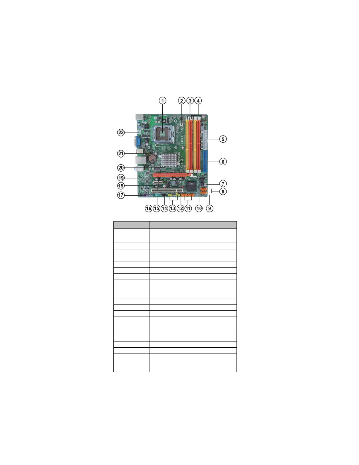
MotherboardComponents
Table of Motherboard Components
This concludes Chapter 1. The next chapter explains how to install the motherboard.
LABEL COMPONENTS
LGA775 socket for Intel®Conroe
/
Presler
/
Wolfdale/Yorkfield processors
2. CPU_FAN CPU cooling fan connector
3. DDR3_1~2 240-pin DDR3 SDRAM slots
4. DDR2_1~2 240-pin DDR2 SDRAM slots
5. ATX_POWER Standard 24-pin ATX power connector
6. IDE Primary IDE channel
7. SYS_FAN System cooling fan connector
8. SATA3~4 Serial ATA connectors
9. CASE Chassis detect header
10. CLR_CMOS Clear CMOS jumper
11. SATA1~2 Serial ATA connectors
12. USBPWR_F Front panel USB power select jumper
13. F_USB1~2 Front panel USB headers
14. F_PANEL Front panel switch/LED header
15. COM Onboard serial port header
16. SPDIFO SPDIF out header
17. F_AUDIO Front panel audio header
18. PCI 32-bit add-on card slot
19. PCIE PCI Express x1 slot
20. PCIEX16 PCI Express x16 graphics card slot
21. USBPWR_R Rear panel USB PS/2 power select jumper
22. ATX12V 4-pin +12V power connector
1. CPU Socket

7
InstallingtheMotherboard
Chapter2
InstallingtheMotherboard
SafetyPrecautions
• Follow these safety precautions when installing the motherboard
• Wear a grounding strap attached to a grounded device to avoid dam-
age from static electricity
• Discharge static electricity by touching the metal case of a safely
grounded object before working on the motherboard
• Leave components in the static-proof bags they came in
• Hold all circuit boards by the edges. Do not bend circuit boards
ChoosingaComputer Case
There are many types of computer cases on the market. The motherboard complies
with the specifications for the Micro ATX system case. First, some features on the
motherboard are implemented by cabling connectors on the motherboard to indica-
tors and switches on the system case. Make sure that your case supports all the
features required. Secondly, this motherboard supports two enhanced IDE drives.
Make sure that your case has sufficient power and space for all drives that you intend
to install.
Most cases have a choice of I/O templates in the rear panel. Make sure that the I/O
template in the case matches the I/O ports installed on the rear edge of the
motherboard.
This motherboard carries a Micro ATX form factor of 225 x 190 mm. Choose a case
that accommodates this form factor.
Installingthe Motherboard inaCase
Refer to the following illustration and instructions for installing the motherboard in
a case.
Most system cases have mounting brackets installed in the case, which correspond
the holes in the motherboard. Place the motherboard over the mounting brackets
and secure the motherboard onto the mounting brackets with screws.
Ensure that your case has an I/O template that supports the I/O ports and expansion
slots on your motherboard.

8
InstallingtheMotherboard
CheckingJumperSettings
This section explains how to set jumpers for correct configuration of the motherboard.
SettingJumpers
Use the motherboard jumpers to set system configuration options. Jumpers with
more than one pin are numbered. When setting the jumpers, ensure that the jumper
caps are placed on the correct pins.
The illustrations show a 2-pin jumper.
When the jumper cap is placed on both
pins, the jumper is SHORT. If you re-
move the jumper cap, or place the jumper
cap on just one pin, the jumper is OPEN.
This illustration shows a 3-pin jumper.
Pins 1 and 2 are SHORT.
SHORT OPEN
Do not over-tighten the screws as this can stress the motherboard.
9
InstallingtheMotherboard
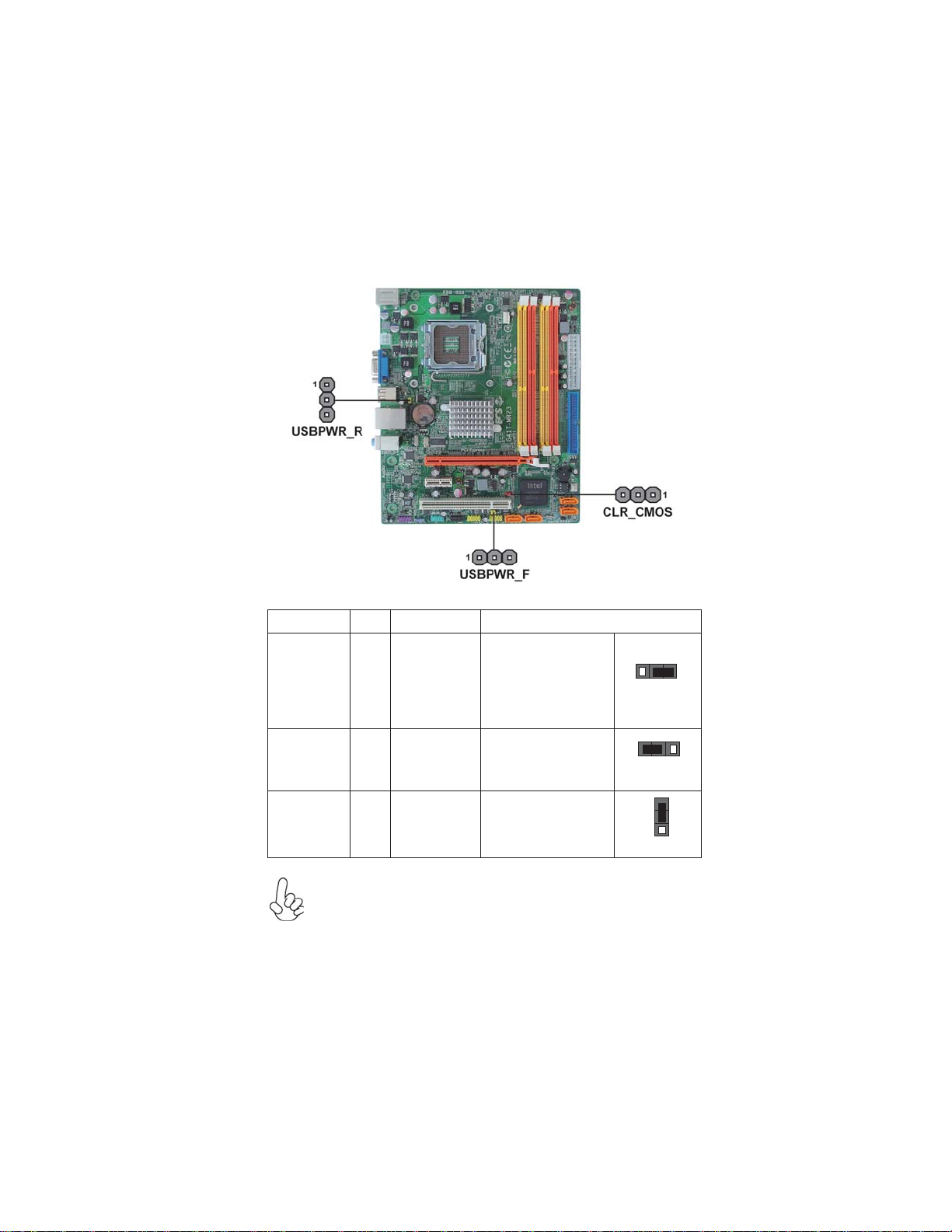
Checking Jumper Settings
The following illustration shows the location of the motherboard jumpers. Pin 1 is
labeled.
JumperSettings
USBPWR_F
USBPWR_R
Jumper Type Description Setting (default)
CLR_CMOS 3-pin Clear CMOS
1-2: NORMAL
2-3: CLEAR
Before clearing the
CMOS, make sure to
turn off the system.
CLR_CMOS
USBPWR_F 3-pin
USBPWR_R 3-pin Rear USB PS/2
Power Select
Jumper 2-3: 5VSB
1-2: VCC 1
Front Panel
USB Power 1-2: VCC
2-3: 5VSB
1
1
Select Jumper
1. To avoid the system instability after clearing CMOS, we recommend
users to enter the main BIOS setting page to “Load Default Settings” and
then “Save and Exit Setup”.
2. Make sure the power supply provides enough 5VSB voltage before select-
ing the 5VSB function.
3. It is required that users place the USBPWR_F & USBPWR_R cap onto 2-
3 pin rather than 1-2 pin as default if you want to wake up the computer by
USB/PS2 KB/Mouse.

10
InstallingtheMotherboard
InstallingHardware
Installing the Processor
Caution: When installing a CPU heatsink and cooling fan make sure
that you DO NOT scratch the motherboard or any of the surface-
mount resistors with the clip of the cooling fan. If the clip of the cooling
fan scrapes across the motherboard, you may cause serious damage
to the motherboard or its components.
On most motherboards, there are small surface-mount resistors near
the processor socket, which may be damaged if the cooling fan is
carelessly installed.
Avoid using cooling fans with sharp edges on the fan casing and the
clips. Also, install the cooling fan in a well-lit work area so that you
can clearly see the motherboard and processor socket.
Before installing the Processor
This motherboard automatically determines the CPU clock frequency and system bus
frequency for the processor. You may be able to change the settings in the system
Setup Utility. We strongly recommend that you do not over-clock processors or
other components to run faster than their rated speed.
This motherboard has an LGA775 socket. When choosing a processor, consider the
performance requirements of the system. Performance is based on the processor
design, the clock speed and system bus frequency of the processor, and the quantity
of internal cache memory and external cache memory.
2. Always remove the AC power by unplugging the power cord from
the power outlet before installing or removing the motherboard or
other hardware components.
Warning:
1. Over-clocking components can adversely affect the reliability of the
system and introduce errors into your system. Over-clocking can per-
manently damage the motherboard by generating excess heat in com-
ponents that are run beyond the rated limits.
Fail-Safe Procedures for Over-clocking
When end-users encounter failure after attempting over-clocking, please take the
following steps to recover from it.
1. Shut down the computer.
2. Press and hold the “Page Up Key (PgUp)” of the keyboard, and then boot the
PC up.
3. Two seconds after the PC boots up, release the “Page Up Key (PgUp)”.
4. The BIOS returns to the default setting by itself.

11
InstallingtheMotherboard
A. Read and follow the instructions shown
on the sticker on the CPU cap.
B. Unload the cap
· Use thumb & forefinger to hold the
lifting tab of the cap.
· Lift the cap up and remove the cap
completely from the socket.
C. Open the load plate
· Use thumb & forefinger to hold the
hook of the lever, pushing down and
pulling aside unlock it.
· Lift up the lever.
· Use thumb to open the load plate. Be
careful not to touch the contacts.
D. Install the CPU on the socket
· Orientate CPU package to the socket.
Make sure you match triangle marker
to pin 1 location.
E. Close the load plate
· Slightly push down the load plate onto
the tongue side, and hook the lever.
· CPU is locked completely.
F. Apply thermal grease on top of the CPU.
G. Fasten the cooling fan supporting base
onto the CPU socket on the motherboard.
H. Make sure the CPU fan is plugged to the
CPU fan connector. Please refer to the
CPU cooling fan user’s manual for more
detail installation procedure.
CPU Installation Procedure
The following illustration shows CPU installation components.
1. To achieve better airflow rates and heat dissipation, we suggest
that you use a high quality fan with 3800 rpm at least. CPU fan and
heatsink installation procedures may vary with the type of CPU fan/
heatsink supplied. The form and size of fan/heatsink may also vary.
2. DO NOT remove the CPU cap from the socket before installing a
CPU.
3. Return Material Authorization (RMA) requests will be accepted
only if the motherboard comes with the cap on the LGA775 socket.

12
InstallingtheMotherboard
Installing Memory Modules
This motherboard accommodates two memory modules. It can support two 240-pin
DDR3 1333 (OC)/1066/800, the total memory capacity is 8 GB; it can also support
two 240-pin DDR2 800, the total memory capacity is 8 GB too.
Do not remove any memory module from its antistatic packaging until
you are ready to install it on the motherboard. Handle the modules only
by their edges. Do not touch the components or metal parts. Always
wear a grounding strap when you handle the modules.
You must install at least one module in any of the two slots. The total memory
capacity is up to 8 GB.
DDR3 SDRAM memory module table
DDR3 1066 533 MHz
Memory module Memory Bus
DDR3 800 400 MHz
You must install at least one module in any of the two slots. The total memory
capacity is up to 8 GB.
DDR2 SDRAM memory module table
Memory module Memory Bus
DDR3 800 400 MHz
DDR3 1333 667 MHz
Users pleased be noted that DDR3 & DDR2 memory modules can not be
installed at the same time. When DDR3 memory modules have been in-
stalled, you can not install DDR2 memory modules, vice versa.

13
InstallingtheMotherboard
Installation Procedure
Refer to the following to install the memory modules.
1 This motherboard supports unbuffered DDR3/DDR2 SDRAM .
2 Push the latches on each side of the DIMM slot down.
3 Align the memory module with the slot. The DIMM slots are keyed with
notches and the DIMMs are keyed with cutouts so that they can only be
installed correctly.
4 Check that the cutouts on the DIMM module edge connector match the
notches in the DIMM slot.
5 Install the DIMM module into the slot and press it firmly down until it
seats correctly. The slot latches are levered upwards and latch on to
the edges of the DIMM.
6 InstallanotherDDR3 or DDR2 DIMM module.
DDR3 DIMM slots: Yellow
DDR2 DIMM slots: Orange
14
InstallingtheMotherboard
Table A: DDR2 (memory module) QVL (Qualified Vendor List)
The following DDR2 800/667 memory modules have been tested and qualified for
use with this motherboard.
Type Size Vendor Module Name
512 MB Micron MT4HTF6464AY-667E1
78.01G9O.9K5
667/AU01GE667C5KBGC
Corsair VS1GB667D2
Kingston KVR667D2N5
Micron MT8HTF12864AY-667E1
AL7E8E63B-6E1T
AL7E8F63J-6E1
AL7E8F73C-6E1
Samsung Gold Bar M378T2863DZS
Apacer 78.A1G9O.9K4
Hynix HYMP125U64AP8-Y5
Kingston KVR667D2N5
LeadMax PC2-5300U
PSC AL8E8F73C-6E1
A-DATA M2GVD6G3I41P0U1E5E
78.01GAO.9K5
78.01GA0.9L5
AU01GE800C5KBGC
Geil Geil Millenary
Hynix HYMP112U64CP8-S6 AB
KingMax KLDD48F-B8KU5 NGES
Kingston KVR800D2N5/1G 1.8V 9905316-054.A01LF
Nanya NT1GT64U88D0BY-AD
Ramaxel RML1320EH38D7F-800
Golden Bar M378T2953EZ3-CE7 0726
M378T2863EHS-CF7
Transcend DDR/DIMM 5-5-5
Unifosa GU341G0ALEPR6B2C6CE
DDR2 667
1 GB
PSC
2 GB
Apacer
Apacer
1 GB
DDR2 800
Samsung

15
InstallingtheMotherboard
Type Size Vendor Module Name
DDR3 800 512 MB Qimonda IMSH51U03A1F1C-08E
Elpida PC3-8500U-7-00-AP
Kingston KVR1066D3N7/512
Aeneon AEH760UD00-10FA98X
Elpida EBJ10UE8BDF0-A E-F
HYMT112U64ZNF8-G8 AA
HMT112U6AFP8C-G7N0 AA
Kingston KVR1066D3N7
IMSH1GU03A1F1C-10F
IMSH1GU03A1F1C-10G
Samsung M378B2873EH1-CF8
MT8JTF12864AY-1G1D1
MT8JTF12864AY-1G1D1
MT8JTF12864AZ-1G1F1
Ramaxel RMR1810NA48E7F-1066-LF
M2Y2G64CB8HC9N-BE
M2Y2G64CB8HC5N-BE
Elpida EBJ21UE8BDF0-A E-F
HYMT125U64ZNF8-G8 AA
HMT125U6AFP8C-G7N0 AA
MT16JTF25664AY-1G1D1
MT16JTF25664AY-1G1D1
MT16JTF25664AZ-1G1F1
Nanya M2Y2G64TU8HD5B-BD
IMSH2GU13A1F1C-10F
IMSH2GU13A1F1C-10G
M378B5673DZ1-CF8
M378B5673DZ1-CF8
Qimonda
Qimonda
Samsung
Hynix
M378B2873DZ1-CF8Samsung
DDR3 1066
Elixir
Hynix
Micron
Micron
512 MB
2 GB
1 GB
Table B: DDR3 (memory module) QVL (Qualified Vendor List)
The following DDR3 2200/2133/2000/1800/1600/1333/1066/800* memory mod-
ules have been tested and qualified for use with this motherboard.

16
InstallingtheMotherboard
Type Size Vendor Module Name
A-DATA AD3U1333B1G9-B
Aeneon AXH760UD00-13GA98X
Elixir M2Y1G64CB88A5N-CG
Elpida EBJ10UE8BDF0-DJ-F
Hynix HMT112U6AFP8C-H9N0 AA
KingsMax FLFD45F-B8KG9 NAUS
KingMax FLFD45F-B8KG9 NAES
KVR1333D3N9
KVR1333D3N9
MT8JTF12864AY-1G4D1
MT8JTF12864AZ-1G4F1
Nanya NT1GC64B88A0NF-CG
PSC AL7F8G73D-DG1
Qimonda IMSH1GU13A1F1C-13H
RMR1810KD48E7F-1333
RMR1810E7F-1333
M378B2873DZ1-CH9
M378B2873EH1-CH9
M378B2873FHS-CH9
Silicon Pow er SP001GBLTU133S01
Unifosa GU502203EP0201
A-DATA AD3U1333B2G9-B
A-data Game A-DATA 8-8-8-24
Apacer 78.A1GC6.9L1
M2F2G64CB8HA4N-CG
M2Y2G64CB8HC9N-CG
M2Y2G64CB8HA5N-CG
Elpida EBJ21UE8BDF0-DJ-F
F3-10666CL9D-4GBRL
F3-10666CL8D-4GBECO 1.35V
F3-10666CL9D-4GBNQ
Hynix HMT125U6AFP8C-H9N0 AA
KingMax FLFE85F-B8KG9 NEES
KingsMax FLFE85F-B8KG9 NEUS
KVR1333D3N9
KVR1333D3N9
KVR1333D3N9K2/2G
KVR1333D3N9/2G
Micron MT16JTF25664AY-1G4D1
Nanya NT2GC64B8HAONF-CG
PSC AL8F8G73D-DG1
Qimonda IMSH2GU13A1F1C-13H
Ramaxel RMR186EA48D8F-1333
M378B5673EH1-CH9
M378B5673FH0-CH9
Unifosa GU512303EP0202
Winchip GDF2GB18L150C8
Kingston KVR1333D3N9/4G
Samsung M378B5273CH0-CH9
1 GB
2 GB
4 GB
DDR3 1333
Kingston
Micron
Ramaxel
Samsung
Elixir
G.SKILL
Kingston
Samsung
Table of contents
Other ECS Motherboard manuals


