ECS P4ITA2 User manual

This publication, photographs, illustrations and software are
under the protection of international copyright laws and all
rights reserved. It does not allow any reproduction of this
manual, content and any materials contained herein without
the written consent of the authentic manufacturer.
The information in this manual is subject to change without
notice. The manufacturer does neither represent nor warrant
the contents hereof; and specifically disclaims any implied
warranties of merchantability or fitness for any particular pur-
pose. Furthermore, the manufacturer reserves the right to
revise and change this publication from time to time, without
the obligation of notifying any person of such revision or
changes.
Trademarks
IBM, VGA, and PS/2 are registered trademarks of Interna-
tional Business Machines.
Intel, Pentium, Pentium-II, and MMX are registered trade-
marks of Intel Corporation.
Microsoft, MS-DOS and Windows 95/98/NT/2000 are regis-
tered trademarks of Microsoft Corporation.
PC-cillin and ChipAwayVirus are trademarks of Trend Micro
Inc.
AMI is a trademark of American Megatrends, Inc.
MediaRing Talk is a registered trademark of MediaRing Inc.
3Deep is a registered trademark of E-Color Inc.
It has been acknowledged that all mentioned brands or prod-
uct names are trademarks or registered trademarks of their
respective holders.
Copyright © 2001
All Rights Reserved
P4ITA2, V1.0

ii
Federal Communications Commission (FCC)
This equipment has been tested and found to comply with the limits
for a Class B digital device, pursuant to Part 15 of the FCC Rules.
These limits are designed to provide reasonable protection against
harmful interference in a residential installation. This equipment gen-
erates, uses, and can radiate radio frequency energy and, if not
installed and used in accordance with the instructions, may cause
harmful interference to radio communications. However, there is no
guarantee that interference will not occur in a particular installation. If
this equipment does cause harmful interference to radio or television
reception, which can be determined by turning the equipment off
and on, the user is encouraged to try to correct the interference by
one or more of the following measures:
−Reorient or relocate the receiving antenna.
−Increase the separation between the equipment and the
receiver.
−Connect the equipment onto an outlet on a circuit different
from that to which the receiver is connected.
−Consult the dealer or an experienced radio/TV technician
for help.
Shielded interconnect cables and a shielded AC power cable must
be employed with this equipment to ensure compliance with the per-
tinent RF emission limits governing this device. Changes or
modifications not expressly approved by the system's manufacturer
could void the user's authority to operate the equipment.

iii
Table of Contents
Chapter 1: Introduction .............................................................1
Key Features.............................................................2
Package Contents .....................................................5
Static Electricity Precautions......................................6
Pre-Installation Inspection .........................................6
Chapter 2: Mainboard Installation...............................................7
Mainboard Components.............................................8
I/O Ports ..................................................................9
Installing the Processor..............................................9
Installing Memory Modules..................................... 11
Jumper Settings ...................................................... 12
Panel Connector...................................................... 13
Other Devices Installation....................................... 14
Expansion Slots Installation..................................... 14
Connecting Optional Devices................................... 16
Chapter 3: BIOS Setup Utility.................................................. 18
Introduction............................................................ 18
Running the SetupUtility .………………………. …..19
Standard CMOS Setup Page .................................... 20
Advanced Setup Page.............................................. 21
Power Management Setup Page ............................... 23
PCI / Plug and Play Setup Page................................ 25
Load Optimal Settings ............................................ 26
Load Best Performance Settings .............................. 26
Features Setup Page ............................................... 27
CPU PnP Setup Page .............................................. 28
Hardware Monitor Page .......................................... 29
Exit ....................................................................... 29
Chapter 4: Using the Mainboard Software................................. 30
About the Software CD-ROM.................................. 30
Auto-installing under Windows 98........................... 31
Drivers Installation.................................................. 35
Utility Software Reference....................................... 37

iv

1
Chapter 1
Introduction
Congratulations on purchasing the P4ITA2 mainboard. The P4ITA2
mainboard is an ATX mainboard that uses a 6-layer printed circuit
board and measures 305 x 244mm. The mainboard features a Socket
423 that accommodates Intel Pentium 4 processors supporting front
side bus (FSB) speeds up to 400 MHz and data bus bandwidths up to
3.2 GB/s.
The P4ITA2 incorporates the Intel Tehama 850 Northbridge and Intel
82801BA (ICH2) Southbridge chipsets, combining support for dual-
channel RAMBUS DRAM (RDRAM), 2X/4X AGP (1.5V only), and
the AC 97 codec.
The Intel 82801I/O controller hub includes an integrated audio-codec
controller that lets the processor efficiently decode sound generated by
the integrated audio system.

2
Key Features
This mainboard has these key features:
Socket 423 Processor
♦The PGA Socket 423
♦Accommodates Intel Pentium 4 CPUs
♦Supports a front-side bus (FSB) of 400 MHz
♦Supports 3.2 GB/s data bus bandwidth
Chipset
Intel’s innovative Tehama 850 Northbridge and 82801 Southbridge
chipsets are based on an innovative and scaleable architecture with
proven reliability and performance. A few of the advanced features of
the chipsets are:
♦Host interface controller supports 400 MHz frontside (system)
bus frequency
♦Supports up to 2 GB of Rambus DRAM
♦Supports a maximum memory bandwidth of 3.2 GB/s
♦AGP controller is AGP 2.0 compliant and supports 2x/4x Fast
Write Protocol (1.5V only)
♦PCI IDE controller supports PCI bus mastering, PIO modes
0~4, and UDMA 33/66/100
♦Two USB controllers double the bandwidth to 24 Mbps across
four ports
♦Integrated AC 97 audio that supports full surround sound with
up to 2 channels
Additional key features include support for four USB ports, an AC 97
link for audio and modem, hardware monitoring, and ACPI/OnNow
power management.
Memory Support
♦The mainboard accommodates Rambus DRAM up to 2 GB
using 2.5V unbuffered Rambus DRAM (RDRAM) memory
modules.

3
VGA
♦The P4ITA2 includes a 4xAGP slot that provides four times
the bandwidth of the original AGP specification. AGP tech-
nology provides a direct connection between the graphics sub-
system and the processor so that the graphics do not have to
compete for processor time with other devices on the PCI bus.
AC 97 Audio Codec
♦The AC 97 Audio codec is compliant with the AC 97 2.1
specification, and supports 18-bit ADC (Analog Digital Con-
verter) and DAC (Digital Analog Converter) resolution as
well as 18-bit stereo full-duplex codec with independent and
variable sampling rates.
Expansion Options
The mainboard comes with the following expansion options:
♦Five 32-bit PCI slots
♦A 4xAGP slot (AGP Pro slot optional)
♦A Communications Network Riser (CNR) slot
♦Two IDE channels and a floppy disk drive interface
The P4ITA2 supports Ultra DMA bus mastering with transfer rates of
33/66/100 MB/sec.
Onboard I/O Ports
The mainboard has a full set of I/O ports and connectors:
♦Two PS/2 ports for mouse and keyboard
♦Two serial ports
♦One parallel port
♦One MIDI/game port
♦Two USB ports
♦Audio jacks for microphone, line-in and line-out

4
BIOS Firmware
This mainboard uses AMI BIOS that enables users to configure many
system features including the following:
♦Power management
♦Wake-up alarms
♦CPU parameters and memory timing
♦CPU and memory timing
The firmware can also be used to set parameters for different proces-
sor clock speeds.
Bundled Software
♦PC-Cillin 2000 provides automatic virus protection under
Windows 95/98/NT/2000
♦MediaRing Talk provides PC to PC or PC to Phone internet
phone communication
♦3Deepdelivers the precise imagery and displays accurate
color in your monitor
♦WinDVD2000 is a DVD playback application (optional)
Dimensions
♦ATX form factor of 305 x 244 mm

5
Package Contents
Your mainboard package contains the following items:
qThe mainboard
qThe User’s Guide
qOne diskette drive ribbon cable and bracket
qOne IDE drive ribbon cable and bracket
qOne auto-install software support CD
qRetention modules (already mounted on the board)
qTwo CPU retention brackets
qTwo dummy Rambus DRAM modules (already inserted in RIMM
slots)
Optional Accessories
You can purchase the following optional accessories for this main-
board.
qExtended USB module
qCNR v.90 56K Fax/Modem card

6
Static Electricity Precautions
Components on this mainboard can be damaged by static electricity.
Take the following precautions when unpacking the mainboard and
installing it in a system.
1. Keep the mainboard and other components in their original static-
proof packaging until you are ready to install them.
2. During installation, wear a grounded wrist strap if possible. If you
don’t have a wrist strap, discharge static electricity by touching the
bare metal of the system chassis.
3. Handle the mainboard carefully by the edges. Avoid touching the
components unless it is absolutely necessary. During installation
put the mainboard on top of the static-protection packaging it came
in with the component side facing up.
Pre-Installation Inspection
Inspect the mainboard for damage to the components and
connectors on the board.
If you suspect that the mainboard has been damaged, do not
connect power to the system. Contact your mainboard vendor and
report the damage.

7
Chapter 2
Mainboard Installation
To install this mainboard in a system, follow the procedures in this
chapter:
qIdentify the mainboard components
qInstall a CPU
qInstall two or more system memory modules
qVerify that all jumpers or switches are set correctly
qInstall the mainboard in a system chassis (case)
qConnect any extension brackets or cables to connecting headers
on the mainboard
qInstall other devices and make the appropriate connections to the
mainboard connecting headers
Note:
1. Before installing this mainboard, make sure jumper JBAT1 is set to
Normal setting. See this chapter for information on locating JBAT1
and the setting options.
2. Never connect power to the system during installation. Doing so
may damage the mainboard.

8
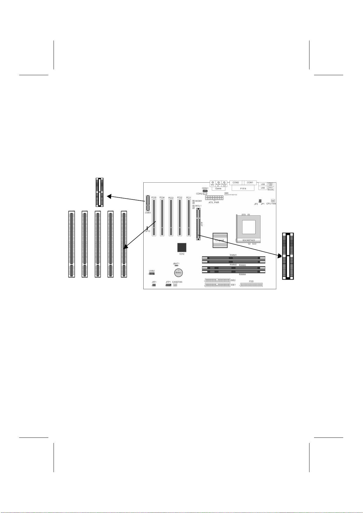
Mainboard Components
Note: Any jumpers on your mainboard that do not appear in this il-
lustration are for testing only.
9
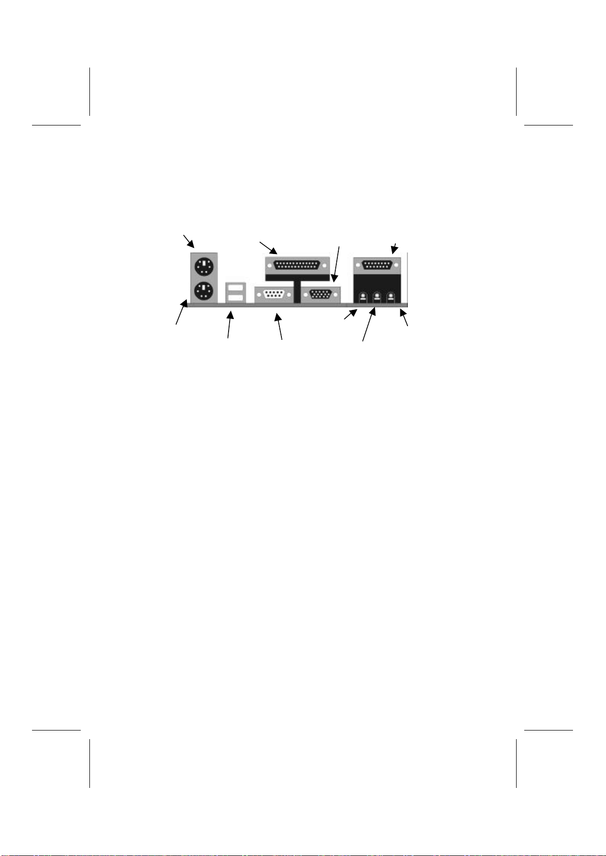
I/O Ports
The backplane of the mainboard has a full set of I/O ports:
PS/2 Mouse
PS/2 Keyboard
Parallel Port Game/MIDI Port
Serial Port COM1/3
USB Ports Microphone Jack
Line Out Jack
COM2/4
LIne In Jack
1. Use the upper PS/2 port to connect a PS/2 pointing de-
vice. Use the lower PS/2 port to connect a PS/2
keyboard.
2. Use the USB ports to connect USB devices.
3. Use LPT1 to connect printers or other parallel com-
munications devices.
4. Use the COM ports to connect serial devices such as
mice or fax/modems. COM1 is identified by the sys-
tem as COM1/3. COM2 is identified by the system as
COM2/4.
5. Use the game port to connect a joystick or a MIDI de-
vice.
6. Use the three audio ports to connect audio devices.
The left side jack is for a stereo line-out signal. The
middle jack is for a stereo line-in signal. The right side
jack is for a microphone.
Installing the Processor
This mainboard has a Socket 423 processor socket. When choosing a
processor, consider the performance requirements of the system. Per-
formance is based on the processor design, the clock speed and system
bus frequency of the processor, and the quantity of internal cache
memory and externalcache memory.

10
CPU Installation Procedure
The following illustration shows CPU installation components:
CPU fan
Pin-1 corner Socket 423
Locking lever Retention modules
Follow these instructions to install the CPU:
1. Pull the CPU socket locking lever away from the
socket to unhook it and raise the locking lever to the
upright position.
2. Identify the pin-1 corner on the CPU socket and the
pin-1 corner on the processor.
3. Match the pin-1 corners and insert the processor into
the socket. Do not use force.
4. Swing the locking lever down and hook it under the
latch on the edge of the socket.
5. Apply thermal grease to the top of the CPU.
6. Insert the CPU cooling fan/heatsink assembly.
7. Plug the CPU fan cable connector into the CPU cool-
ing fan power supply on the mainboard (CFAN).
8. Insert the retention module clips over the edge of the
CPU fan/heatsink assembly.

11
Installing Memory Modules
This mainboard accommodates 184-pin 2.5V unbuffered Rambus
DRAM (RDRAM) memory modules. The memory chips must be
standard or registered RDRAM. The memory bus runs at 400 MHz.
Installation Procedure
The mainboard has four RIMM (Rambus DIMM) slots that accommo-
date up to 2 GB of memory. You can only install the memory modules
in pairs; therefore, you must install at least two RIMM modules. The
dummy Rambus DRAM modules (C-RIMM) must be inserted in un-
populated slots.
1. Align the memory module with the slot. The RIMM
slots are keyed with notches and the RIMMs are keyed
with cutouts so that they can only be installed correctly.
2. Push the latches on each side of the RIMM slot down.
3. Check that the cutouts on the RIMM module edge
connector match the notches in the RIMM slot.
Cutouts
Notches
Latch
Latch
4. Install the RIMM module into the slot and press it
firmly down so that it seats correctly. The slot latches
are levered upwards and latch on to the edges of the
RIMM when it is installed correctly.
5. Install any remaining RIMM modules.

12
6. After installing your RIMM modules, insert the C-
RIMM modules in the unoccupied slots:
RIMM2
RIMM4
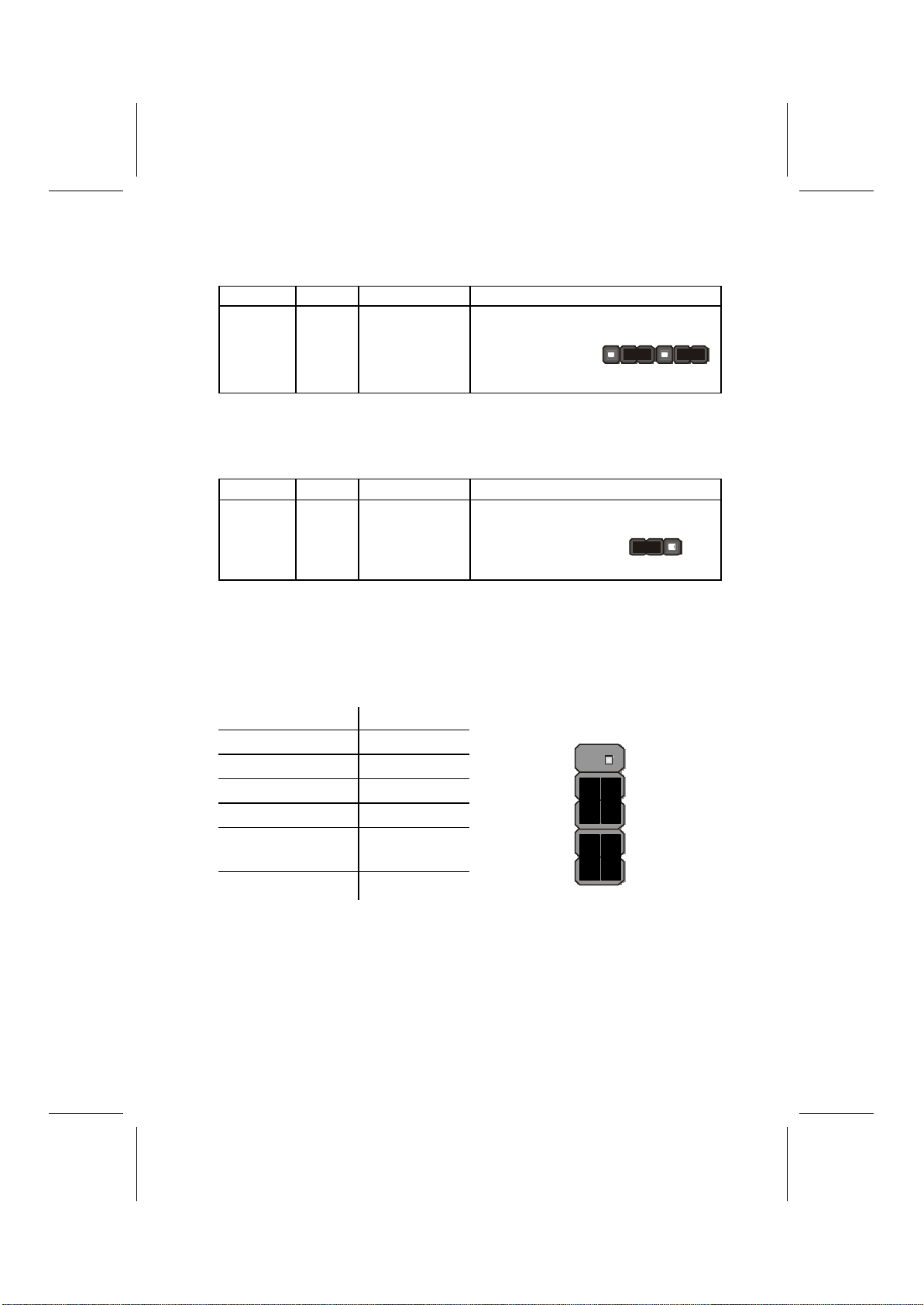
Jumper Settings
Jumper JBAT1 –enables you to clear the BIOS:
1. Turn the system off.
2. Remove all ATX power connectors.
3.Short pins 2 and 3 on JBAT1.
4.Return the jumper to the normal setting.
5.Plug in all ATX power connectors
6.Turn the system on. The BIOS is returned to the default settings.
Jumper Type Description Setting (default)
JBAT1 3 pin Clear CMOS 1-2: Normal
2-3: Clear
JBAT1
1
13
Jumper 1 & Jumper 2 –enable this jumper if you want keyboard
activity to turn on the computer.
Jumper Type Description Setting (default)
JP1 &
JP2
3 pin
3 pin
Keyboard
power on 1-2: Enable
2-3: Disable
JP1
1
JP2
1
Jumper 12 –This jumper enables or disables the onboard audio
codec.
Jumper Type Description Setting (default)
JP12 3 pin Enable on-
board audio
codec
1-2: Enable
2-3: Disable JP12
1
The Panel Connector
The panel connector provides a standard set of switch and LED con-
nectors usually found on ATX or micro-ATX cases. Refer to the table
below for information:
Device Pins
Empty 10
N/C 9
Power ON/OFF 6, 8
Reset Switch 5, 7
Green LED
Indicator +2, -4
HDD LED +1, -3
HDD LED
(Pins 1, 3)
2 1
Reset Switch
(Pins 5, 7)
PowerSwitch
(Pins 6, 8)
Green LED
(Pins 2, 4)
Empty
(Pin10)
10 9
N/C
(Pin9)

14
Other Devices Installation
Floppy Diskette Drive Installation
The mainboard has a floppy diskette drive (FDD) interface ships with
a diskette drive ribbon cable that supports one or two floppy diskette
drives. You can install a 5.25-inch drive and a 3.5-inch drive with
various capacities. The floppy diskette drive cable has one type of
connector for a 5.25-inch drive and another type of connector for a
3.5-inch drive.
IDE Devices
Your mainboard has a primary and secondary IDE channel interface
(IDE1 and IDE2). An IDE ribbon cable supporting two IDE devices is
bundled with the mainboard. IDE devices have jumpers or switches
that are used to set the IDE device as MASTER or SLAVE. Refer to
the IDE device user’s manual.
If you want to install more than two IDE devices, get a second IDE
cable and you can add two more devices to the secondary IDE channel.
When installing two IDE devices on one cable, ensure that one device
is set to MASTER and the other device is set to SLAVE.
This mainboard supports UltraDMA 33/66/100. UDMA is a technol-
ogy that accelerates the performance of devices in the IDE channel.
Install IDE devices that support UDMA and use IDE cables that sup-
port UDMA for better performance.
Expansion Slots Installation
This mainboard has five 32-bit PCI (Peripheral Components Intercon-
nect) expansion slots, one 4xAGP slot, and one Communications and
Networking Riser (CNR) slot.
PCI Slots
PCI slots are used to install expansion cards that have the
32-bit PCI interface.
15
4 x AGP Slot
The 4xAGP slot is used to install a graphics adapter that supports the
4xAGP specification and has a 4xAGP edge connector. The 4xAGP
slot only supports 1.5V 4xAGP and 2xAGP cards.
CNR Slot
This slot is used to insert CNR cards including LAN, Modem, and
Audio functions.
1. Remove a blanking plate from the system case corre-
sponding to the slot you are going to use.
2. Install the edge connector of the add-on card into the
expansion slot. Ensure that the edge connector is cor-
rectly seated in the slot.
3. Secure the metal bracket of the card to the system case
with a screw.
PCI1 PCI2 PCI3 PCI4 PCI5
AGP
CNR1

16
Connecting Optional Devices
WOL1/WOM1: Wake On LAN/Wake On Modem
If you have installed a LAN card, use the cable provided with the card
to plug into the mainboard WOL1 connector. This enables the Wake
On LAN (WOL) feature. When your system is in a power-saving
mode, any LAN signal automatically resumes the system. You must
enable this item using the Power Management page of the Setup Util-
ity.
Pin Signal Name
1
2
3
5VSB
Ground
SENSE
If you have installed a modem, use the cable provided with the modem
to plug into the mainboard WOM1 connector. This enables the Wake
On Modem (WOM) feature.
When your system is in a power-saving mode, any modem signal
automatically resumes the system. You must enable this item using the
Power Management page of the Setup Utility. See Chapter 3 for more
information.
USB2: USB port 3, 4
The mainboard has two USB ports installed on the rear edge I/O port
array. However, some computer cases have a special module that
mounts USB ports at the front of the case. If you have this kind of
case, use auxiliary USB connectors USB2 and USB3 to connect the
front-mounted ports to the mainboard.
Pin Signal Name Pin Signal Name
1
3
5
7
9
Port 3 power
Port 3 USB-
Port 3 USB+
Port 3 ground
Protection key
2
4
6
8
10
Port 4 power
Port 4 USB-
Port 4 USB+
Port 4 ground
Over current sensor
Table of contents
Other ECS Motherboard manuals


