ECS ST945GM User manual


Preface
ii
ii
i
Preface
Copyright
This publication, including all photographs, illustrations and software, is protected under
international copyright laws, with all rights reserved. Neither this manual, nor any of the
material contained herein, may be reproduced without written consent of the author.
Version 1.0
Disclaimer
The information in this document is subject to change without notice. The manufacturer
makes no representations or warranties with respect to the contents hereof and specifically
disclaims any implied warranties of merchantability or fitness for any particular purpose.
The manufacturer reserves the right to revise this publication and to make changes from
time to time in the content hereof without obligation of the manufacturer to notify any
person of such revision or changes.
TrademarkRecognition
Microsoft, MS-DOS and Windows are registered trademarks of Microsoft Corp.
MMX, Pentium, Pentium-II, Pentium-III, Celeron are registered trademarks of Intel Cor-
poration.
Other product names used in this manual are the properties of their respective owners and
are acknowledged.
FederalCommunicationsCommission(FCC)
This equipment has been tested and found to comply with the limits for a Class B digital
device, pursuant to Part 15 of the FCC Rules. These limits are designed to provide reason-
able protection against harmful interference in a residential installation. This equipment
generates, uses, and can radiate radio frequency energy and, if not installed and used in
accordance with the instructions, may cause harmful interference to radio communications.
However, there is no guarantee that interference will not occur in a particular installation.
If this equipment does cause harmful interference to radio or television reception, which
can be determined by turning the equipment off and on, the user is encouraged to try to
correct the interference by one or more of the following measures:
• Reorient or relocate the receiving antenna
• Increase the separation between the equipment and the receiver
• Connect the equipment onto an outlet on a circuit different from that to which
the receiver is connected
• Consult the dealer or an experienced radio/TV technician for help
Shielded interconnect cables and a shielded AC power cable must be employed with this
equipment to ensure compliance with the pertinent RF emission limits governing this
device. Changes or modifications not expressly approved by the system’s manufacturer
could void the user’s authority to operate the equipment.

ii
Preface
DeclarationofConformity
This device complies with part 15 of the FCC rules. Operation is subject to the following
conditions:
• This device may not cause harmful interference, and
• This device must accept any interference received, including interference
that may cause undesired operation
CanadianDepartmentofCommunications
This class B digital apparatus meets all requirements of the Canadian Interference-causing
Equipment Regulations.
Cet appareil numérique de la classe B respecte toutes les exigences du Réglement sur le
matériel brouilieur du Canada.
AbouttheManual
The manual consists of the following:
Chapter 1
Introducing the Motherboard
Chapter 2
Installing the Motherboard
Chapter 3
UsingBIOS
Chapter 4
Using the Motherboard Software
Describes features of the motherboard.
Go to Hpage 1
Describes installation of motherboard
components.
Goto Hpage 7
Provides information on using the BIOS
Setup Utility.
Go to Hpage 25
Describes the motherboard software
Go to Hpage 39

iii
TT
TT
TABLE OF CONTENTSABLE OF CONTENTS
ABLE OF CONTENTSABLE OF CONTENTS
ABLE OF CONTENTS
Preface i
Chapter 1
1
IntroducingtheMotherboard 1
Introduction.................................................................................................1
Feature..........................................................................................................2
MotherboardComponents........................................................................5
Chapter 2 77
77
7
Installing the Motherboard 7
SafetyPrecautions......................................................................................7
Choosinga ComputerCase.......................................................................7
Installingthe Motherboard ina Case......................................................7
CheckingJumperSettings.........................................................................8
Setting Jumpers..............................................................................8
Checking Jumper Settings..............................................................9
Jumper Settings..............................................................................9
ConnectingCase Components...............................................................10
Front Panel Header.....................................................................11
InstallingHardware...................................................................................12
Installing the Processor...............................................................12
Installing Memory Modules.........................................................14
Installing a Hard Disk Drive/CD-ROM/SATA Hard Drive........16
Installing a Floppy Diskette Drive...............................................17
Installing Add-on Cards..............................................................18
Connecting Optional Devices......................................................19
ConnectingI/ODevices..........................................................................24
Chapter 3 2525
2525
25
UsingBIOS 25
Aboutthe SetupUtility............................................................................25
The Standard Configuration........................................................25
Entering the Setup Utility..............................................................25
Updating the BIOS.......................................................................27
UsingBIOS................................................................................................27
Standard CMOS Setup.................................................................28
Advanced Setup............................................................................29
Advanced Chipset Setup...............................................................31

iv
Integrated Peripherals.................................................................32
Power Management Setup...........................................................33
PNP/PCI Setup.............................................................................34
PC Health Status..........................................................................35
Frequency /Voltage Control..........................................................37
Load Defaults Setting...................................................................37
Supervisor Passward...................................................................37
User Password.............................................................................38
Save & Exit Setup.........................................................................38
Exit Without Saving.......................................................................38
Chapter 4 3939
3939
39
UsingtheMotherboardSoftware 39
AbouttheSoftwareCD-ROM................................................................39
Auto-installingunderWindows 2000/XP.............................................39
Running Setup..............................................................................40
ManualInstallation..................................................................................42
UtilitySoftwareReference.......................................................................42

1
IntroducingtheMotherboard
Chapter1
IntroducingtheMotherboard
Introduction
Thank you for choosing the ST945GM motherboard. This motherboard is a high perfor-
mance, enhanced function motherboard designed to support the mPGA479 socket for Intel
Core™ Duo/Core™ Solo/Core™ Duo LV/Core™ Duo ULV/Core™ Solo ULV/Celeron M/
Celeron M-ULV processors for high-end business or personal mobile markets.
The motherboard incorporates the 945GM Northbridge (NB) and ICH7-M Southbridge (SB)
chipsets. The Northbridge supports a Front Side Bus (FSB) frequency of 667/533 MHz using
a scalable FSB Vcc_CPU. The memory controller supports dual-channel DDR2 memory
DIMM frequencies of 667/533/400. It supports two DDR2 Sockets with up to maximum
memory of 4 GB.
The ICH7-M Southbridge supports one standard PCI slot with riser card support and one
MINI PCI which are PCI 2.3 compliant. In addition, one PCI Express x1 slot is supported,
fully compliant to the PCI Express Base Specification, Revision 1.0a. It implements an
EHCI compliant interface that provides 480Mb/s bandwidth for six USB 2.0 ports. One
onboard IDE connector supports 2 IDE devices in Ultra ATA100/66/33 mode. The
Southbridge integrates a Serial ATA host controller that is SATA II compliant, supporting
two SATA ports with maximum transfer rate up to 3.0 Gb/s each.
The motherboard is equipped with advanced full set of I/O ports in the rear panel, including
COM1 and COM2, one DVI1 port, four USB ports, one optional LAN port, one optional
1394 port and audio jacks for microphone, line-in and 6-ch line out.

2
IntroducingtheMotherboard
Feature
• AccommodatesIntel PeCore™ Duo/Core™ Solo/Core™DuoLV/Core™ Duo
ULV/Core™ Solo ULV/Celeron M/Celeron M-ULV processors
• Supports a system bus (FSB) of 667/533MHz
The motherboard uses an mPGA479 socket for Intel Core™ Duo/Core™ Solo/Core™
Duo LV/Core™ Duo ULV/Core™ Solo ULV/Celeron M/Celeron M-ULV processorsthat
carries the following features:
Processor
The 945GM Northbridge (NB) and ICH7-M Southbridge (SB) chipsets are based on an
innovative and scalable architecture with proven reliability and performance.
945GM (NB) • Supports 667/533 MHz front side bus (FSB)
• Supports 256-Mb, 512-Mb and 1-Gb DDR2 technologies for
x8 and x16 devices
• Intel Gen 3.5 integrated Graphics Engine
• Supports TV-out, LVDS, CRT and SDVO.
Chipset
ICH7-M (SB) • EnhancedDMAController,interruptcontroller, and timer func-
tions
• Compliant with PCI Express Base Specification, Revision
1.0a
• Compliant with PCI 2.3 specificaiton
• Integrated Serial ATA Host Controller, supported two ports
• Integrated USB 2.0 Host Controll
• Integrated IDE controller supports Ultra ATA100/66/33
• New Docking Support and Low Voltage Mode
• Support for “Intel SpeedStep® Technology” processer
power control and “Depper Sleep” power state
• Supports DDR2 667/533/400 DDR SDRAM with Dual-channel DDR2 archi-
tecture
• Accommodates two unbuffered DIMMs
• Maximum memory supported up to 4 GB
Memory
Graphics
• Intel® Gen 3.5 Integrated Graphics Engine
• 250 MHz core render clock and 200 MHz core display clock at 1.05 V core
voltage
• Supports TV-Out, LVDS, CRT and SDVO
1394a FireWire (Optional)
• Compliant with single chip host controller for IEEE Std 1394-1995 and IEEE
1394a-2000
• Integrated 400 Mb/s 2-Port PHY for the PCI Bus
• 3.3 V Power supply with 5V Tolerant Inputs

3
IntroducingtheMotherboard
Onboard LAN (Optional)
The onboard LAN controller provides the following features:
• Supports IEEE 802.3 u/ab, 802.1p and 802.1q
• Compliant with 10/100/1000 IEEE 802.3
• Supports WOL power management and ACPI 2.0 specification
• Two-Wire Serial Interface (TWSI) for VPD
• Comppliant with PCI Express base specification 1.1
• Compliant to 802.3x flow control
Integrated I/O
The motherboard has a full set of I/O ports and connectors:
• One DVI port
• Two COM ports
• Four USB ports
• One 1394 port (optional)
• One LAN port (optional)
• Audio jacks for microphone, line-in and line-out
The motherboard comes with the following expansion options:
Expansion Options
• One PCI Express x1 slot
• OneMiniPCIslot
• One 32-bit PCI v2.3 compliant slot with riser card support
The motherboard supports UDMA bus mastering with transfer rates of 100/66 MB/s.
• One 40-pin IDE low profile header that support two IDE devices
• Two 7-pin SATA connectors
• One SCN slot for CF (Compact-Flash) card installing
Audio
• Supports 2W/channel
• Compliant with - 65 dB ripple rejection and channel separation, output
referred
• meets very low cross-over distortion
• Wide supply range: 6V-24V
• Compliant with theAC’97 v2.3 CODEC
• Supports 6-channel audio CODEC designed for PC multimidia systems
• Provides three analog line-level strereo inputs with 5-bit volume control:
Line-in, CD, AUX
• Meets Micrsoft WHQL/WLP 2.0 audio requirements
This motherboard may support either of the following Audio chipset:

4
IntroducingtheMotherboard
• Power management
• Wake-up alarms
• CPUparameters
• CPUandmemroytiming
BIOS Firmware
This motherboard uses AMI BIOS that enables users to configure many system features
including the following:
The firmware can also be used to set parameters for different processor clock speeds.
Some hardware specifications and software items are subject to change
with out prior notice.

5
IntroducingtheMotherboard
MotherboardComponents
6
IntroducingtheMotherboard
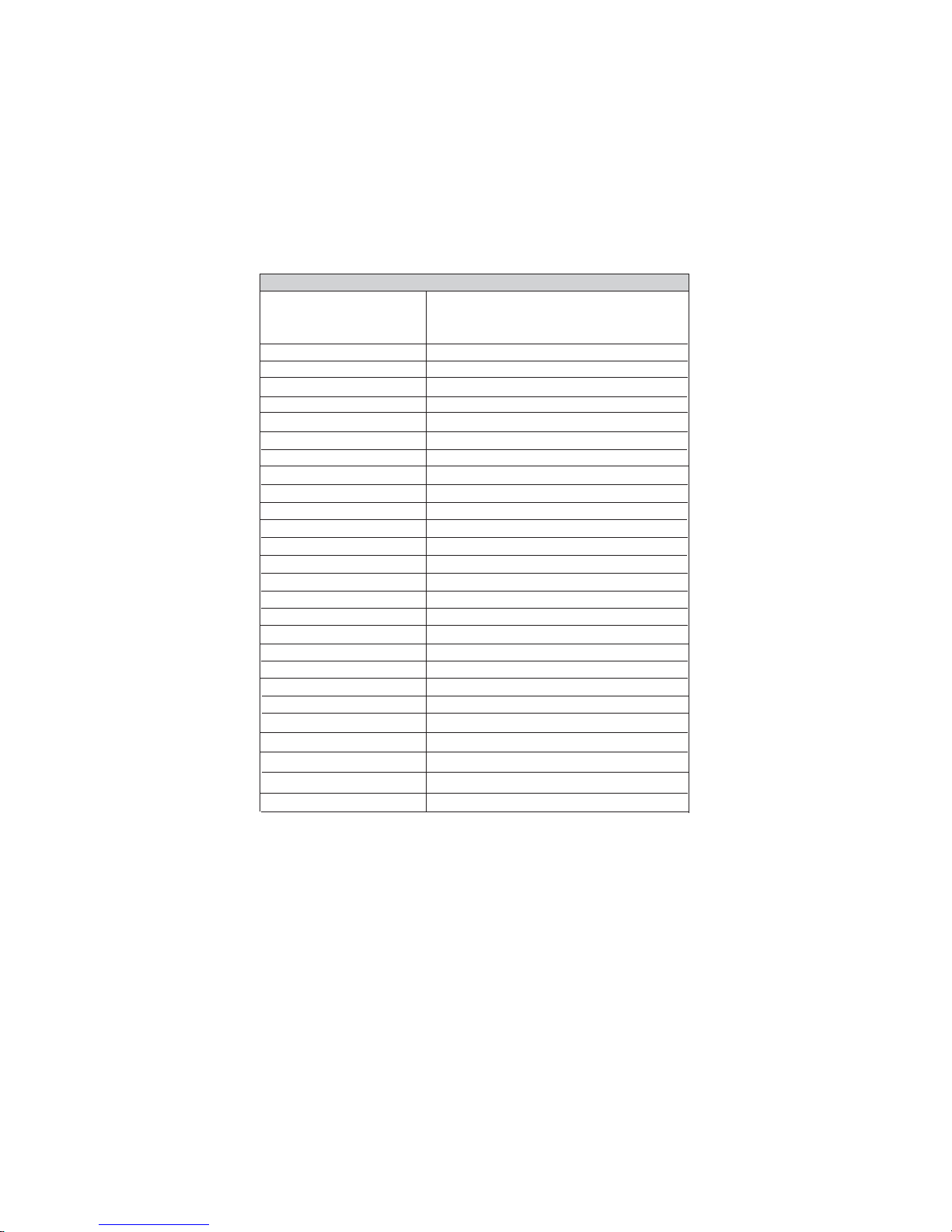
Table of Motherboard Components
2 CPUFAN1 CPU cooling fan connector
LABEL COMPONENT
9 SATA1~2 Serial ATA connectors
10 PCI1 32-bit add-on card slot
5 CF_PWR1 CF power voltage jumper
17 LVDSP1 LVDS Power connector
F**
6 CLR_CMOS Clear CMOS jumper
23 DIO1 Digital IO 3 Channel IN/5 Channel OUT
20 S1 S-Video output connector
19 JP3 LVDS Power jumper
18 CASFAN1 Case cooling fan connector
22 COM3~4 Onboard Serial port haders
21 AV1 AV Composite connector
This concludes Chapter 1. The next chapter explains how to install the motherboard.
mPGA479 socket for Intel Core™ Duo/Core™
Solo/Core™ Duo LV/Core™ Duo ULV/Core™
Solo ULV/Celeron M/Celeron M-ULV CPUs
1 CPU Socket
3 IDE1 Primary IDE channel
4 PANEL1 Panel connector for case switches and LEDs
7 ATX_POWER1 Standard 20-pin ATX power connector
8 PCIE1 PCI Express x1 slot
11 MINI PCI1 Mini PCI type-III socket
12 USB1 Front Panel USB header
13 1394A2 IEEE 1394a header
14 SPKOUT1 External amplifier for internal speaker out
15 AUDIO1 Front panel audio header
16 LVDS1 LVDS connector
24 PSKB1 PS/2 Keyboard Header
25 JP1~2 Select 5/12 V RI Header
26 DIMM1~2 240-pin DDR2 SDRAM slots
27 SCN1 Compact-Flash Type-II socket via IDE bus

7
InstallingtheMotherboard
Chapter2
InstallingtheMotherboard
SafetyPrecautions
• Follow these safety precautions when installing the motherboard
• Wear a grounding strap attached to a grounded device to avoid damage from
static electricity
• Discharge static electricity by touching the metal case of a safely grounded
object before working on the motherboard
• Leave components in the static-proof bags they came in
• Hold all circuit boards by the edges. Do not bend circuit boards
ChoosingaComputerCase
There are many types of computer cases on the market. The motherboard complies with
the specifications for the Mini-ITX system case. First, some features on the motherboard
are implemented by cabling connectors on the motherboard to indicators and switches on
the system case. Make sure that your case supports all the features required. Secondly, this
motherboard supports one or two floppy diskette drives and two enhanced IDE drives.
Make sure that your case has sufficient power and space for all drives that you intend to
install.
Most cases have a choice of I/O templates in the rear panel. Make sure that the I/O
template in the case matches the I/O ports installed on the rear edge of the motherboard.
This motherboard carries an Mini-ITX form factor of 170 x 170 mm. Choose a case that
accommodates this form factor.
InstallingtheMotherboardina Case
Refer to the following illustration and instructions for installing the motherboard in a case.
Most system cases have mounting brackets installed in the case, which correspond the holes
in the motherboard. Place the motherboard over the mounting brackets and secure the
motherboard onto the mounting brackets with screws.
Ensure that your case has an I/O template that supports the I/O ports and expansion slots
on your motherboard.

8
InstallingtheMotherboard
CheckingJumperSettings
This section explains how to set jumpers for correct configuration of the motherboard.
SettingJumpers
Use the motherboard jumpers to set system configuration options. Jumpers with more than
one pin are numbered. When setting the jumpers, ensure that the jumper caps are placed on
the correct pins.
The illustrations show a 2-pin jumper. When
the jumper cap is placed on both pins, the
jumper is SHORT. If you remove the jumper
cap, or place the jumper cap on just one pin,
the jumper is OPEN.
This illustration shows a 3-pin jumper. Pins
1 and 2 are SHORT
SHORT OPEN
Do not over-tighten the screws as this can stress the motherboard.

9
InstallingtheMotherboard
Checking Jumper Settings
The following illustration shows the location of the motherboard jumpers. Pin 1 is labeled.
JumperSettings
Jumper Type Description Setting (default)
CLR_CMOS1 3-pin CLEAR CMOS
1-2: NORMAL
2-3: CLEAR CMOS
Before clearing the
CMOS, make sure to
turn off the system.
CF_PWR1 3-pin CF power voltage
CLR_CMOS1
CF_PWR1
1-2: VCC3
2-3: VCC5 1
JP1/2
11
JP1/2 10-pin Select 5/12V RI 7-9: NRI1/3
8-10: NRI2/4
JP3 3-pin LVDS Power 1-2: VCC3
2-3: VCC5
1
1
JP3

10
InstallingtheMotherboard
ConnectingCaseComponents
After you have installed the motherboard into a case, you can begin con-
necting the motherboard components. Refer to the following:
1 Connect the CPU cooling fan cable to CPUFAN1
2 Connect the system cooling fan connector to CASFAN1
3 Connect the case switches and indicator LEDs to the PANEL1.
4 Connect the standard power supply connector to ATX_POWER1.
CASFAN1:FANPower Connector
Pin Signal Name Function
1GND System Ground
3NC Not connected
2 +12V
CPUFAN1:FANPower Connector
1GND System Ground
2+12V Power +12V
3 Sense Sensor
Pin Signal Name Function
Users please note that the fan connector supports the CPU cooling fan of
1.1A ~ 2.2A (26.4W max) at +12V.
Power +12V

11
InstallingtheMotherboard
ATX_POWER1:ATX 20-pin Power Connector
Pin Signal Name Pin Signal Name
1+3.3V 11 +3.3V
2+3.3V 12 -12V
3Ground 13 Ground
4+5V 14 PSON#
5Ground 15 Ground
6+5V 16 Ground
7Ground 17 Ground
8PWROK 18 -5V
9AUX5V 19 +5V
10 +12V 20 +5V
Front Panel Header
The front panel header (PANEL1) provides a standard set of switch and LED headers
commonly found on ATX or Micro ATX cases. Refer to the table below for information:
Pin Signal Function Pin Signal Function
1 HLED+ Hard disk LED(+) 2 LEDG *MSG LED (+)
3 HLED - Hard disk LED (-)
5 GND Ground
7 REST Reset Switch
9 RSVD Reserved
4 LEDY *MSG LED (-)
6 FP_PSIN Power Switch
8 3VSB Power Switch
10 Key No pin
* MSG LED (dual color or single color)
Hard Drive Activity LED
Connecting pins 1 and 3 to a front panel mounted LED provides visual indication that data
is being read from or written to the hard drive. For the LED to function properly, an IDE
drive should be connected to the onboard IDE interface. The LED will also show activity
for devices connected to the SCSI (hard drive activity LED) connector.
Power/Sleep/Message waiting LED
Connecting pins 2 and 4 to a single or dual-color, front panel mounted LED provides power
on/off, sleep, and message waiting indication.

12
InstallingtheMotherboard
Reset Switch
Supporting the reset function requires connecting pin 5 and 7 to a momentary-contact
switch that is normally open. When the switch is closed, the board resets and runs POST.
Power Switch
Supporting the power on/off function requires connecting pins 6 and 8 to a momentary-
contact switch that is normally open. The switch should maintain contact for at least 50 ms
to signal the power supply to switch on or off. The time requirement is due to internal de-
bounce circuitry. After receiving a power on/off signal, at least two seconds elapses before
the power supply recognizes another on/off signal.
InstallingHardware
Installing the Processor
Caution: When installing a CPU heatsink and cooling fan make sure that
you DO NOT scratch the motherboard or any of the surface-mount
resistors with the clip of the cooling fan. If the clip of the cooling fan
scrapes across the motherboard, you may cause serious damage to the
motherboard or its components.
On most motherboards, there are small surface-mount resistors near the
processor socket, which may be damaged if the cooling fan is carelessly
installed.
Avoid using cooling fans with sharp edges on the fan casing and the clips.
Also, install the cooling fan in a well-lit work area so that you can clearly
see the motherboard and processor socket.
Before installing the Processor
This motherboard automatically determines the CPU clock frequency and system bus
frequency for the processor. You may be able to change these settings by making changes
to jumpers on the motherboard, or changing the settings in the system Setup Utility. We
strongly recommend that you do not over-clock processors or other components to run
faster than their rated speed.
This motherboard has a mPGA479 socket. When choosing a processor, consider the
performance requirements of the system. Performance is based on the processor design, the
clock speed and system bus frequency of the processor, and the quantity of internal cache
memory and external cache memory.
Warning: Over-clocking components can adversely affect the reliability
of the system and introduce errors into your system. Over-clocking can
permanently damage the motherboard by generating excess heat in
components that are run beyond the rated limits.

13
InstallingtheMotherboard
CPU Installation Procedure
The following illustration shows CPU installation components.
A. Locate the key pin (no pin) of the CPU socket.
B. Locate the “triangle mark” on the down left
corner of the CPU.
C. Align the triangle mark with the key pin, and
gently insert the CPU into the CPU socket.
D. Lock the CPU in the CPU socket with a suitable
screwdriver, clockwise to lock it up, or counter-
clockwise to unlock it.
E. Put the CPU Fan Base under the Motherboard,
and aim the CPU Fan at the four CPU Fan Base
holes.
F. Fasten the CPU fan onto the CPU socket with a
screwdriver, and then connect the CPU fan to
the CPU_FAN power connector.

14
InstallingtheMotherboard
Installing Memory Modules
This motherboard accomodates four memory modules. It can support two 240-pin DDR2
667/533/400. The total memory capacity is 4 GB.
You must install at least one module in any of the two slots. Each module can be installed
with 256 MB to 1 GB of memory; total memory capacity is 4 GB.
Do not remove any memory module from its antistatic packaging until you
are ready to install it on the motherboard. Handle the modules only by
their edges. Do not touch the components or metal parts. Always wear a
grounding strap when you handle the modules.
Installation Procedure
Refer to the following to install the memory modules.
1 This motherboard supports unbuffered DDR2 SDRAM .
2 Push the latches on each side of the DIMM slot down.
3 Align the memory module with the slot. The DIMM slots are keyed with notches
and the DIMMs are keyed with cutouts so that they can only be installed
correctly.
4 Checkthat the cutoutson the DIMM module edge connector matchthe notches
inthe DIMM slot.
5 Install the DIMM module into the slot and press it firmly down until it seats
correctly. The slot latches are levered upwards and latch on to the edges of
theDIMM.
6 Installany remaining DIMM modules.
DDR2 SDRAM memory module table
DDR2 533 266MHz
DDR2 667 333MHz
200 MHz
Memory module Memory Bus
DDR2 400
Table of contents
Other ECS Motherboard manuals


