ECS DURATHON 2 H81H3-BTC User manual
Version:1.0
40-012-ME7100
H81H3-BTC

H81H3-BTC USER MANUAL
The information in this document is subject to change without notice. The
manufacturer makes no representations or warranties with respect to the contents
hereof and specifically disclaims any implied warranties of merchantability or
fitness for any particular purpose. The manufacturer reserves the right to revise this
publication and to make changes from time to time in the content hereof without
obligation of the manufacturer to notify any person of such revision or changes.
This equipment has been tested and found to comply with the limits for a Class B
digital device, pursuant to Part 15 of the FCC Rules. These limits are designed to
provide reasonable protection against harmful interference in a residential
installation. This equipment generates, uses, and can radiate radio frequency
energy and, if not installed and used in accordance with the instructions, may cause
harmful interference to radio communications. However, there is no guarantee that
interference will not occur in a particular installation. If this equipment does cause
harmful interference to radio or television reception, which can be determined by
turning the equipment off and on, the user is encouraged to try to correct the
interference by one or more of the following measures:
•Reorient or relocate the receiving antenna
•Increase the separation between the equipment and the receiver
•Connect the equipment onto an outlet on a circuit different from that to
which the receiver is connected
•Consult the dealer or an experienced radio/TV technician for help
Shielded interconnect cables and a shielded AC power cable must be employed with
this equipment to ensure compliance with the pertinent RF emission limits
governing this device. Changes or modifications not expressly approved by the
system’s manufacturer could void the user’s authority to operate the equipment.
Federal Communications Commission (FCC)
Disclaimer
Declaration of Conformity
This device complies with part 15 of the FCC rules. Operation is subject to the follow-
ing conditions:
•This device may not cause harmful interference.
•This device must accept any interference received, including interference
that may cause undesired operation.
Electromagnetic compatibility of multimedia equipment - Emission
requirements
EN 55032
EN 61000-3-2 Electromagnetic Compatibility(EMC)
Part 3-2: Limits-Limits for harmonic current emissions (equipment input
current 16A per phase)
EN 61000-3-3 Electromagnetic Compatibility(EMC)
Part 3-3: Limits-Limitation of voltage changes, voltage fluctuations and flicker
in public low-voltage supply systems, for equipment with rated current 16A
per phase and not subject to conditional connection
EN 55024 Information technology equipment-Immunity characteristics-Limits and
methods of measurement
EN 60950 Safety for information technology equipment including electrical business
equipment
CE marking
This device is in conformity with the following EC/EMC directives:

ii
H81H3-BTC USER MANUAL
TABLE OF CONTENTS
Preface i
Brief Introduction 1
Specifications......................................................................................1
Motherboard Components................................................................3
Header Pin Definition and Jumper Settings.........................................5
I/O Ports...............................................................................................8
Multi-language Quick Installation Guide 9
English...................................................................................................9
Simplified Chinese...............................................................................11
Korean......................................................................................................13
Indonesian.............................................................................................15
Japanese.................................................................................................17
Vietnamese.............................................................................................19

H81H3-BTC USER MANUAL
1
Brief Introduction
CPU
Specifications
• Intel®H81 ChipsetChipset
• Dual-channel DDR3 memory architecture
• 2 x 240-pin DDR3 DIMM sockets support up to 16 GB
• Supports DDR3 1600/1333 MHz SDRAM
Memory
• Supported by Intel®H81 Express Chipset
- 2 x Serial ATA 6Gb/s devices
- 2 x Serial ATA 3Gb/s devices
Expansion
Slots
Storage
• 1 x DVI port
• 4 x USB 2.0 ports
• 1 x RJ45 LAN connector
• 2 x USB 3.0 ports
• 1 x Audio port (1 x line-in, 1 x line-out, 1 x microphone)
Rear Panel I/O
• Realtek ALC662 6-Ch High Definition audio CODEC
- Compliant with HD audio specification
Audio
• LGA1150 socket for Intel® 4th Generation CoreTM Family
processors
• Supports CPU up to 95W TDP
Note: Please go to ECS website for the latest CPU support list.
Note: Please go to ECS website for the latest Memory support list.
• 1 x PCI Express x16 slot (Gray)
• 1 x PCI Express x16 Gen2 slot (Run x1 mode- Black)
• 4 x PCI Express x1 Gen2 slots
Internal I/O
Connectors &
Headers
• 1 x 24-pin ATX Power Supply connector
• 1 x 4-pin ATX 12V Power connector
• 1 x 4-pin PWR_FAN header
• 2 x 4-pin ATX 12V Power connectors for VGA cards
• 1 x 4-pin CPU_FAN header
• 1 x 4-pin SYS_FAN header
• 1 x 4-pin NB_FAN header
• 2 x USB 2.0 headers support additional four USB 2.0 ports
• 2 x SATA 6Gb/s connectors, 2 x SATA 3Gb/s connectors
• 1 x SPDIF out header
• 1 x Front Panel audio header
• 1 x COM header
• 1 x USBPWR_R1 jumper
• 1 x USBPWR_R jumper
• 1 x USBPWR_F1 jumper
• 1 x USBPWR_F jumper
• 1 x CLR_CMOS jumper
• 1 x Parallel port header (LPT)
• 1 x Speaker header
• 1 x Case open header
• Realtek RTL8111G Gigabit LanLAN

H81H3-BTC USER MANUAL
2
QR Code for the complete manual download
on ECS website: http://www.ecs.com.tw
• AMI BIOS with 64Mb SPI Flash ROM
• Supports Plug and Play, STR (S3)/ STD(S4), Hardware Monitor
• Supports ACPI & DMI
• Audio, LAN, can be disabled in BIOS
• F7 hot key for boot up devices option
• Supports PgUp clear CMOS Hotkey (Has PS2 KB Model only)
• Supports EZ BIOS (1024X768 resolution, GUI UEFI)
• Supports Multi-Language
• Supports AC’97/HD Audio auto detect (default)
System BIOS
• ATX Size, 305mm x 190mmForm Factor
• ECS Exclusive AP: Supports eBLU*1/eDLU/eSF*1
AP/Bundled
Software
Support Note: *1Microsoft .NET Framework 3.5 is required.
H81H3-BTC USER MANUAL
3
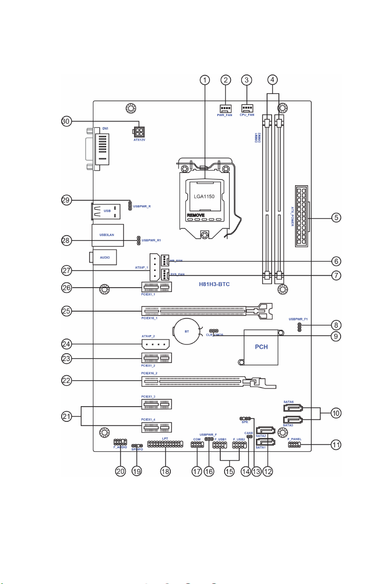
Motherboard Components

H81H3-BTC USER MANUAL
4
Table of Motherboard Components
LABEL COMPONENTS
1. CPU Socket LGA1150 socket for Intel®4th Generation CoreTM Family processors
2. PWR_FAN 4-pin Power cooling fan header
3. CPU_FAN 4-pin CPU cooling fan header
4. DIMM1~2 240-pin DDR3 Module slots
5. ATX_POWER Standard 24-pin ATX power connector
6. NB_FAN 4-pin Northbridge cooling fan header
7. SYS_FAN 4-pin system cooling fan header
8. USBPWR_F1 Front panel USB power select jumper
9. CLR_CMOS Clear CMOS jumper
10. SATA5~6 Serial ATA 3Gb/s connectors
11. F_PANEL Front panel switch/LED header
12. SATA1~2 Serial ATA 6Gb/s connectors
13. SPK Speaker header
14. CASE CASE open header
15. F_USB1~2 Front panel USB 2.0 headers
16. USBPWR_F Front panel USB power select jumper
17. COM Onboard serial port header
18. LPT Parallel port header
19. SPDIFO SPDIF out header
20. F_AUDIO Front panel audio header
21. PCIEX1_3~4 PCI Express Gen2 x1 slots
22. PCIEX16_2 PCI Express x16 slot for graphics interface
23. PCIEX1_2 PCI Express Gen2 x1 slot
24. ATX4P_2 4-pin +12V power connector for VGA card
25. PCIEX16_1 PCI Express x16 slot for graphics interface
26. PCIEX1_1 PCI Express Gen2 x1 slot
27. ATX4P_1 4-pin +12V power connector for VGA card
28. USBPWR_R1 Rear USB3LAN power select jumper
29. USBPWR_R Rear USB/PS2 power select jumper
30. ATX12V 4-pin +12V power connector

5
H81H3-BTC USER MANUAL
F_AUDIO
1
1
9
F_USB1~2
1
1
COM
Key
PORT 1L
PORT 1R
PORT 2R
AUD_GND
AUD_GND
PRESENCE#
SENSE1_RETURN
Key
SENSE2_RETURN
KEY
NC
KEY
1
F_PANEL
Hard disk LED (-)
Hard disk LED (+)
Reset Switch (-)
Reset Switch (+)
Reserved
Power Switch (-)
Power Switch (+)
MSG LED (+)
MSG LED (-)
Ground
Ground
Power +5V
SPDIF OUT
Ground
USB Port B (-)
USB Port A (+)
VCC
USB Port B (+)
KEY
Serial Output
Data Carrier Detect
Serial Input
Ring Indicator
Data Terminal Ready Clear to Send
Request to Send
Data Set Ready
Ground
PORT 2L
SPDIFO
Power +5V
USB Port A (-)

H81H3-BTC USER MANUAL
6
CPU_FAN / PWR_FAN
Sensor
PWM
System Ground
Power +12V
SYS_FAN / NB_FAN
1
Sensor
PWM
System Ground
Power +12V
1
LPT
1
INIT
Ground
SLCT
Ground
Key
Ground
Ground
AFD
ERROR
Ground
Ground
Ground
Ground
PD1
PD5
PD2
PD6
SLCT
PD4
PD3
STROBE
PD0
PD7
ACK
BUSK
PE
SPK
1
Signal
Ground
VCC

7
H81H3-BTC USER MANUAL
CLR_CMOS Jumper
1-2: NORMAL
Before clearing the CMOS, make sure to turn off the system.
CLR_CMOS
312 2-3: CLEAR CMOS
1
IntruderGround
CASE
USBPWR_R1 / USBPWR_R Jumper
ATX4P_1
1-2: VCC
3
1
2
2-3: 5VSB
3
1
2
USBPWR_F1 Jumper
1-2: VCC
132
2-3: 5VSB
USBPWR_F Jumper
132
1-2: VCC
1
3
2
2-3: 5VSB
1
3
2
ATX4P_2
+12V
1
Ground
Ground
NC
+12V
1
Ground
Ground
NC
H81H3-BTC USER MANUAL
8
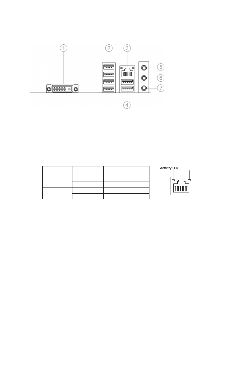
I/O Ports
1. DVI Port
Connect your monitor to the DVI port.
2. USB 2.0 Ports
Use the USB 2.0 ports to connect USB 2.0 devices.
3. LAN Port
Connect an RJ-45 jack to the LAN port to connect your computer to the Network.
4. USB 3.0 Ports
Use the USB 3.0 ports to connect USB 3.0 devices.
5. Line-in(blue)
It can be connected to an external CD/DVD player, Tape player or other audio
devices for audio input.
6. Line-out(lime)
It is used to connect to speakers or headphones.
7. Microphone(pink)
It is used to connect to a microphone.
LAN LED Status Description
OFF No data
Orange blinking Active
OFF No link
Green Link
Activity LED
Link LED
Link LED
LAN Port

9
English
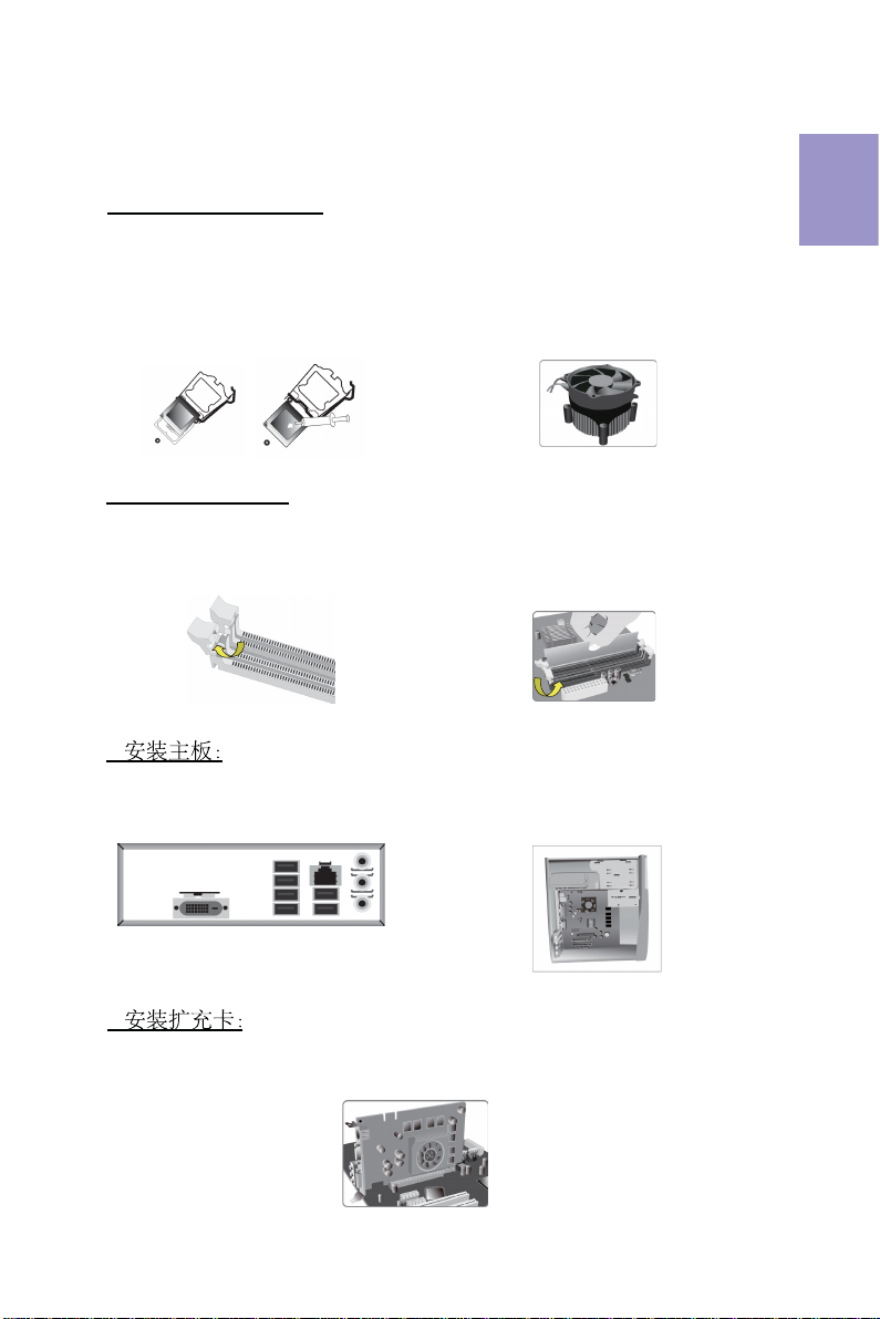
Step 1. Installation of the CPU and CPU Cooler:
Hardware Installation Guide
Installation Steps
1-1. Pull up the lever away from the
socket. Align the CPU cut edge with the
indented edge of the CPU socket.
Gently place the CPU into correct
position. Apply an even layer of thermal
grease on the surface of CPU.
Step 2. Installation of Memory Modules:
2-1. Unfasten the latches on each side
of the DIMM slots.
Step 3. Installation of Motherboard:
3-1. Replace the back I/O plate of the
case with the I/O shield provided in
motherboard’s package.
1-2. Rotate and press down the fastener
of CPU fan to the motherboard through
holes to install CPU fan into place.
2-2. Firmly press the DIMM down until it
seats correctly. Make sure the slot
latches are levered upwards and latch
on the edge of the DIMM.
3-2. Place the motherboard within the
case by positioning it into the I/O plate.
Secure the motherboard to the case
with screws.
Step 4. Installation of an Expansion card:
Remove the metal located on the slot and then insert the expansion card into the
slot. Press the card firmly to make sure it is fully inserted into its slot. And then
return the screw back to its position.
10
English
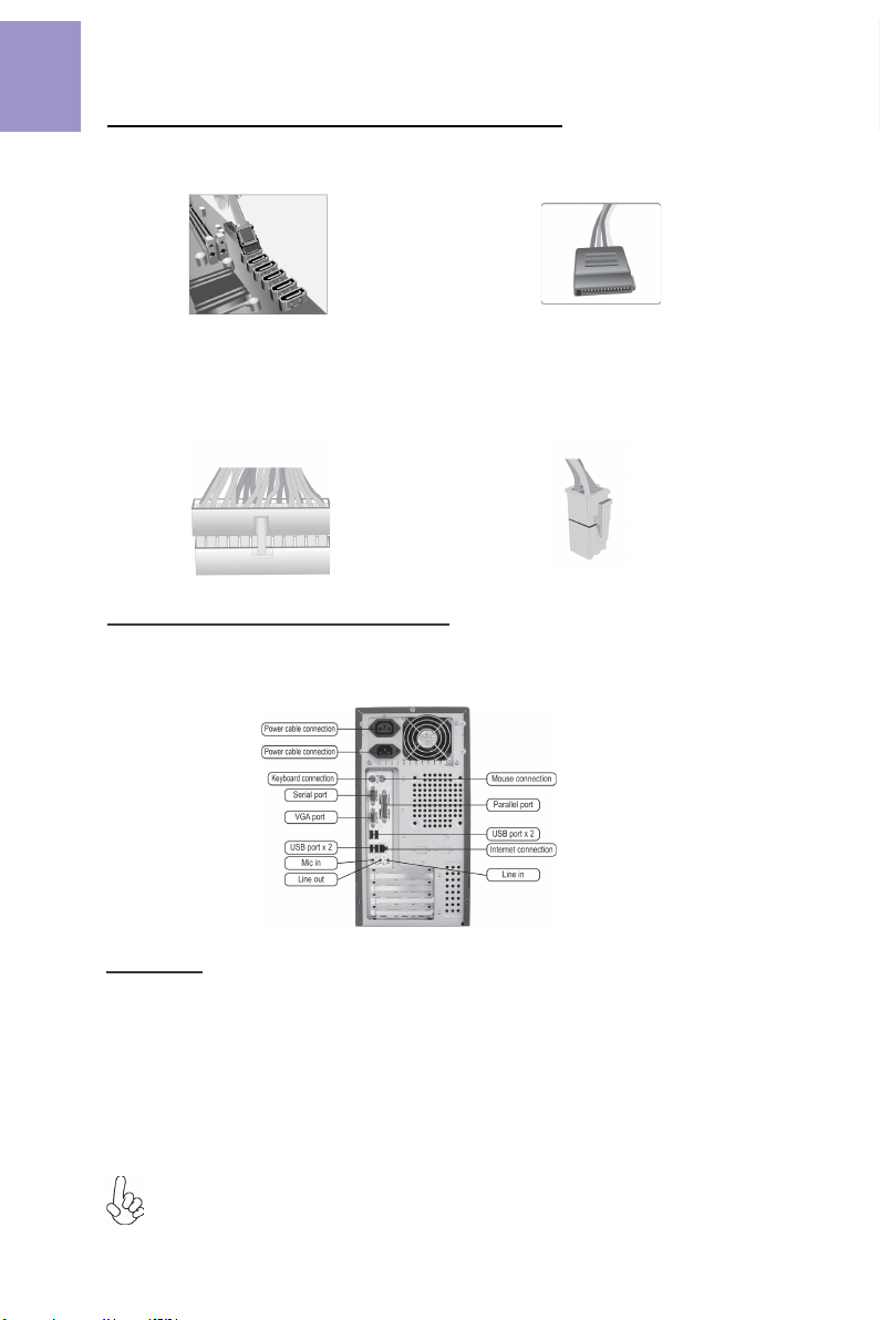
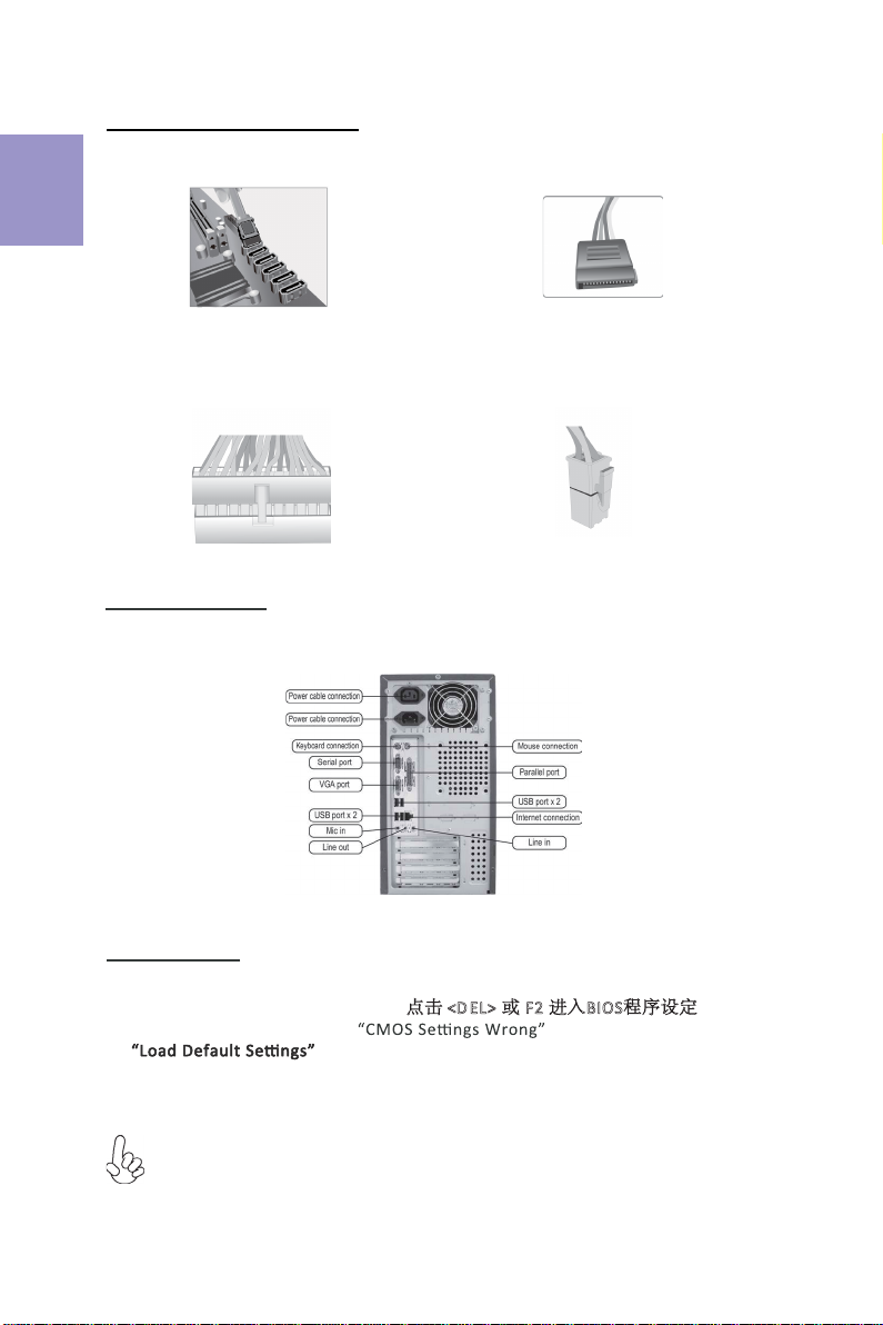
Step 5. Connecting Cables and Power Connectors:
c. Connect 24-pin power cable
The ATX_12V 4-Pin power connector is used
to provide power to the CPU. When installing
4-pin power cable, the latch of power cable
matches the ATX_12V connector perfectly.
b. Connect SATA power connector to the
SATA device
Once the steps above have been completed, please connect the peripherals such
as the keyboard, mouse, monitor, etc. Then, connect the power and turn on the
system. Please install all the required software.
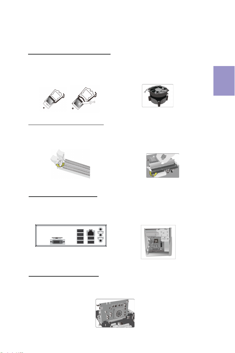
Step 6: Connecting ports on the case:
a. Connect the SATA hard drive to its
SATA cable
d. Connect 4-pin power cable
Please note that when installing 24-pin
power cable, the latches of power cable
and the ATX connector match perfectly.
The sequence of installation may differ depending on the type of case and
devices used.
Using BIOS
The BIOS (Basic Input and Output System) Setup Utility displays the system’s
configuration status and provides you options to set system parameters. When
you power on the system, BIOS enters the Power-On Self Test (POST) routines,
please press <DEL> or F2 to enter setup. When powering on for the first time, the
POST screen may show a “CMOS Settings Wrong” message. Please enter BIOS and
choose “Load Default Settings” to reset the default CMOS values. (Changes to
system hardware such as different CPU, memories, etc. may also trigger this
message.)
11
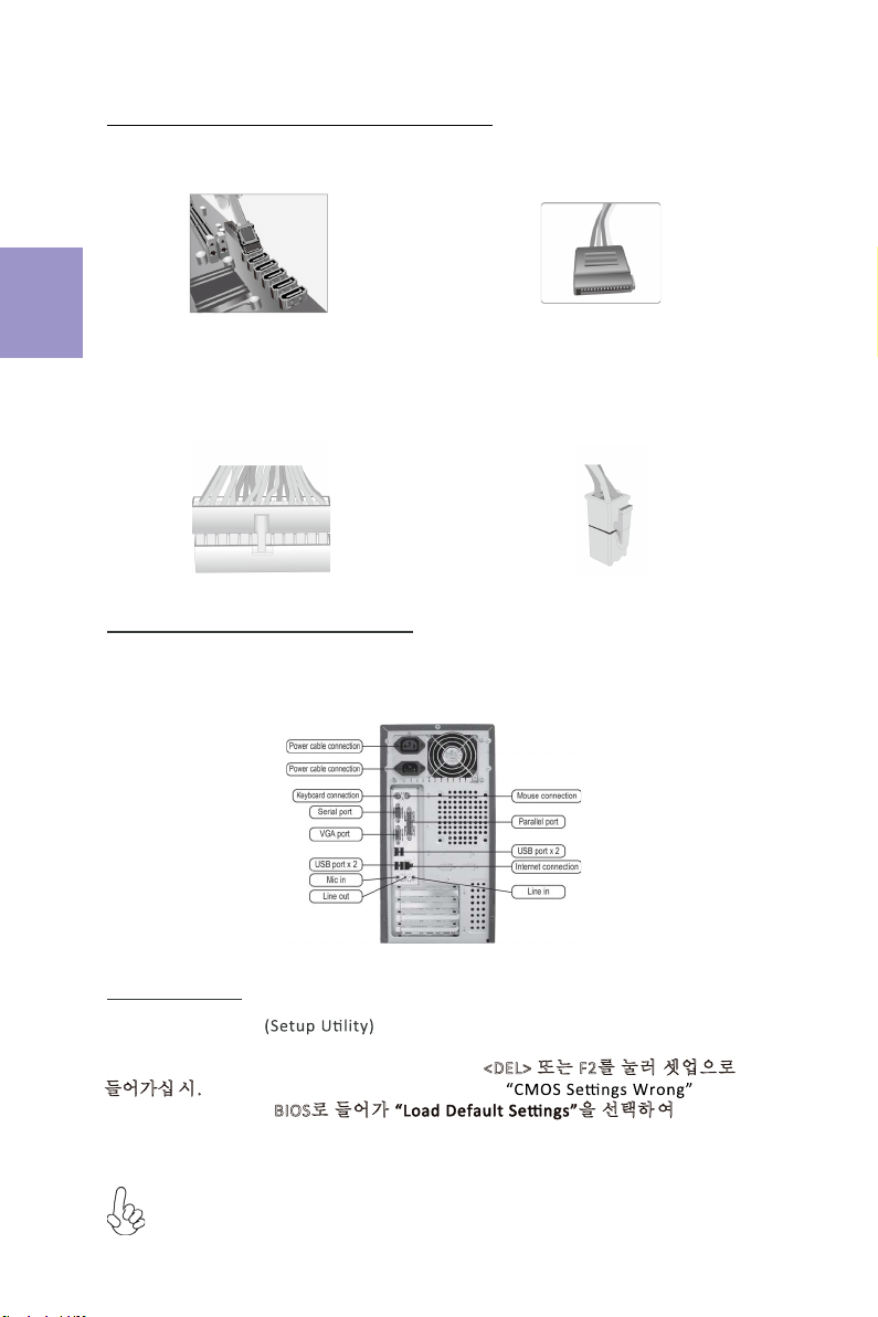
1.安装CPU和CPU风扇:
硬件安装指南
安装步骤
1-1. 松开CPU插槽旁的固定杆,向
上拉固定杆,并掀开插槽上的保
护盖。
2.安装记忆体模组:
2-1. 向外扳开内存插槽两端的卡扣。
3.
3-1. 取下机箱后面的I/O挡板,换上主
板附带的I/O弹片。
将CPU边缘的缺口对准 CPU
插槽标示边缘,小心地将CPU
插
置入
槽。
滑的
然后在CPU表层涂抹一层平
散热膏。
1-2. 将CPU风扇扣具对齐主板上的对应
孔位,向下按压并且旋转扣具,固定
CPU风扇。
2-2. 对准内存插槽,将内存条往下按直至完
全插入。正确安装后插槽两端的卡扣会自动
锁住内存条边 缘。
3-2. 将主板的后I/O对准机箱上的I/O挡板孔
位,放入机箱并以螺丝固定。
4.
移除机箱后面的扩充金属挡板,确认扩充卡完全插入扩展 槽后,重新拧上螺丝。
简体中文
12
5.连接电源线与电源接头:
c. 连接24针电源线与电源接头
4针电源接头提供CPU电源。其电源接头与电
源线必须完全扣合。
b. 将SATA电源接头连接至SATA设备a. 将SATA电缆连接至SATA 硬盘
d. 连接4针电源线与电源接头
请注意电源接头与电源线必须完全扣合。
简体中文
当上述安装步骤完成后,请开始安装键盘,鼠标,
源并启
显示器等外围设备,然后连接电
动系统。请安装好所需的软件。
6.连接机箱端口:
此说明内容中提供图片或安装方式仅供参考。
BIOS使用设定
BIOS程序画面会显示系统配置,同时提供操作选项让您设定系统参数。当开机时,
BIOS会进行开机自我测试 (POST),请点击<D EL> 或F2 进入BIOS程序设定。第一次
开机时,POST画面可能会显示 信息,请进入BIOS选单并选
择将BIOS重新设定为默认值 (更换CPU或内存等硬件变更也
可能会出现此信息)。
13
모듈 설치하기:
1단계. CPU와CPU
하드웨어 설치 가이드
단계별 설치 방법
1-1. 소켓에서 레버를 뽑아 냅니다.
2단계. 메모리
2-1. DIMM 슬롯의 각측면에 있는
걸쇠를 풉니다.
3단계. 마더보드 설치하기:
3-1. 케이스의 후면 I/O 플레이트를
마더보드의 패키지에 제공된 I / O
실드로 교체합니다.
CPU
끝부분을 CPU 소켓의 들어간 끝부분에
맞춥니다. CPU를정확한 위치에살며시
위치시킵니다. CPU의표면에 써멀
그리스를 고르게 도포합니다.
1-2. 패스너를 돌려 CPU 팬을 마더보드
의쓰루-홀에 눌러 넣어 CPU 팬을 제위치
에설치합니다.
2-2. DIMM이정확하게 설치될 때까지 단
단히 누릅니다. 슬롯 걸쇠를 위로
DIMM의 가장자리를 잠급니다..
3-2. 마더보드를 I/O 플레이트에
위치시
켜케이스 내에.
스크류로
마더보드를
케이스에 고정시킵니다.
쿨러 설치하기:
한국어
올려
4단계. 확장 카드 설치하기:
슬롯에 설치되어 있는 금속을 제거하고 확장 카드를 해당 슬롯에 삽입합니다. 슬롯에
완전히 삽입될 수있도록 카드를단단히 누릅니다. 스크류를 다시 제자리에 체결합니다.
14
5단계. 케이블 및전원 커넥터 연결하기:
c. 4핀전원 케이블을 연결합니다
ATX_12V 4핀전원 커넥터는 전원을 CPU에
공급하기 위해 사용됩니다. 4핀전원 케이블
설치시에는, 전원 케이블의 걸쇠가 ATX_12V
커넥터와 완벽하게 맞아야 합니다.
b. SATA 전원 커넥터를 SATA 장치에 연결합
니다
a. SATA 하드 드라이브를 SATA
케이블에 연결합니다
d. 4핀전원 케이블을 연결합니다
24핀전원 케이블 연결시 전원 케이블과
ATX 커넥터의 걸쇠가 완벽하게 맞아야
합니다.
한국어
일단 위의 단계들이 완료되면, 키보드, 마우스, 모니터 등과 같은 주변기기들을
연결
합니다. 그런 후에, 전원을 연결하고 시스템을 켭니다. 모든 필수 소프트웨어를 설치
합니다.
6단계. 케이스의 포트 연결하기:
BIOS 사용하기
BIOS 셋업 유틸리티 는시스템의 환경설정 상태를 표시하며 시스템
매개변수를 설정하기 위한 옵션을 제공합니다. 시스템의 전원을 켜면, BIOS는
Power-On Self Test (POST) 루틴을 실행합니다, <DEL> 또는 F2를눌러 셋업으로
들어가십 시.오 처음으로 전원을 켜면 POST 화면에 메시지가
나타날 수 있습니다. BIOS로들어가 을선택하 여 기본 CMOS
설정값을 재설정합니다. (CPU, 메모리 등과 같은 시스템 변경할 때에도 본 메뉴가
나타날 수있습니다.)
설치절차는 사용된 케이스 및장치의 유형에 따라 다를 수있습니다.
15
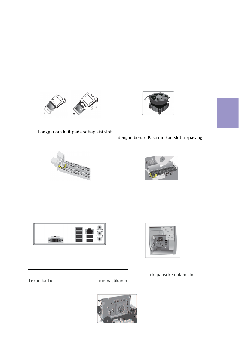
Langkah 1. Pemasangan CPU dan Pendingin CPU:
Panduan Pemasangan Perangkat Keras
Langkah-Langkah Pemasangan
1-1. Tarik tuas dari soket.
Langkah 2. Pemasangan Modul Memori:
2-1.
DIMM.
Langkah 3. Pemasangan Motherboard:
3-1. Pasang kembali pelat I/O casing
dengan pelindung I/O yang disediakan
dalam paket motherboard.
Luruskan
tepi pemisah CPU dengan tepi
bertakik dari soket CPU. Pasang CPU
secara perlahan pada posisi yang
tepat. Oleskan lapisan gemuk termal
secara merata pada permukaan CPU.
1-2. Putar dan tekan penahan kipas
CPU
ke lubang tembus motherboard untuk
memasang kipas CPU pada tempatnya.
2-2. Tekan kuat DIMM hingga terpasang
pada tuas atas dan kaitkan pada tepi DIMM.
3-2. Tempatkan motherboard pada casing
dengan memosisikannya ke dalam pelat I/O.
Kencangkan motherboard pada casing
dengan
sekrup.
Bahasa
Indonesia
Langkah 4. Pemasangan kartu Ekspansi:
Lepaskan logam yang terletak pada slot lalu masukkan kartu
dengan kencang untuk ahwa kartu telah masuk sepenuhnya ke
dalam slot. Lalu pasang kembali sekrup ke dalam posisinya.
16
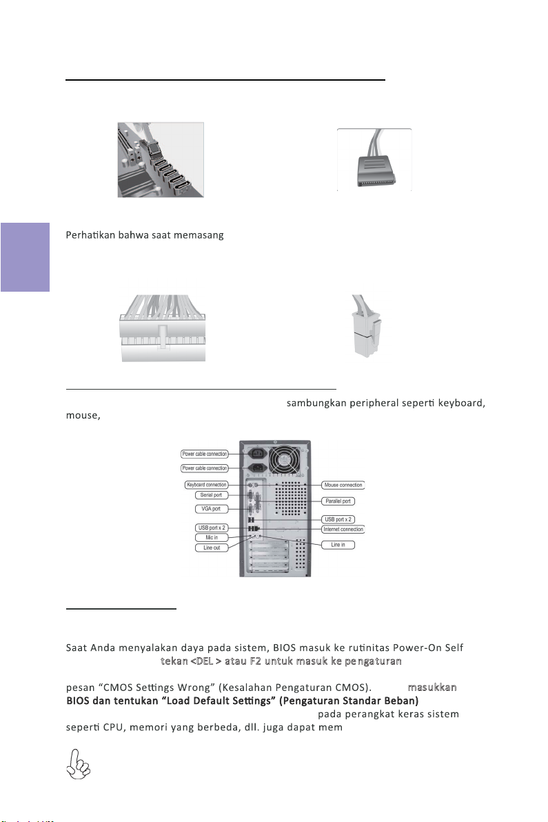
Langkah 5. Menyambungkan Kabel dan Konektor Daya:
c. Sambungkan kabel daya 24 pin
Konektor daya ATX_12V 4 pin digunakan untuk
menyediakan daya ke CPU. Saat memasang kabel
daya 4 pin, kait kabel daya cocok dengan konektor
ATX_12V.
a. Sambungkan hard drive SATA ke kabel
SATA
b. Sambungkan konektor daya SATA ke
perangkat SATA
d. Sambungkan kabel daya 4 pin
kabel daya 24, kait pada kabel daya
dan konektor ATX harus sesuai.
Bahasa
Indonesia
Setelah langkah-langkah di atas selesai, harap
monitor, dll. Lalu sambungkan daya dan nyalakan sistem. Harap pasang semua
perangkat lunak yang dibutuhkan.
Langkah 6. Menyambungkan port pada casing:
Menggunakan BIOS
Utulitas Pengaturan BIOS (Basic Input and Output System) menampilkan status
kongurasi sistem dan memberi Anda opsi untuk mengatur parameter sistem.
Test (POST), harap tekan <DEL > atau F2untuk masuk ke pe nga turan. Saat
menyalakan untuk pertama kalinya, layar POST mungkin akan menunjukkan
untuk
icu pesan ini.)
Harap masukkan
menyetel kembali nilai CMOS standar. (Perubahan
Urutan pemasangan mungkin berbeda bergantung pada jenis casing dan
perangkat yang digunakan.

17
ࣁ࣮ࢻ࢙࢘ࣥࢫࢺ࣮ࣝ࢞ࢻ
ࣥࢫࢺ࣮ࣝᡭ㡰
ᡭ㡰㸯㹁㹎㹓㹁㹎㹓ࢡ࣮࣮ࣛࡢࣥࢫ
ࢺ࣮ࣝ㸸
1-2. CPUファンの留め具を回転させてマザー
ボードのスルーホールに押し入れ、CPUファ
ンを適切な位置に設置します。CPUクーラー
の電源コネクタをCPU_FANコネクタに接
続します。
ᡭ㡰㸰࣓ࣔࣜࣔࢪ࣮ࣗࣝࡢࣥࢫࢺ࣮ࣝ㸸
2-2. DIMMが正しく固定されるまでしっかり
と押します。スロットのラッチが上に持ち上が
り、DIMMの端を留めていることを確認しま
す。
ᡭ㡰㸱࣐ࢨ࣮࣮࣎ࢻࡢࣥࢫࢺ࣮ࣝ㸸
3-2. I/Oプレートにマザーボードを位置決め
し、ケース内に配置します。ネジでマザーボー
ドをケースに固定します。
ᡭ㡰㸲ࢫࢺ࣮ࣞࢪࢹࣂࢫࡢࣥࢫࢺ࣮ࣝ㸸
日本語
2-1. DIMMスロット各側のラッチを緩めます。
3-1. ケースの背面I/Oプレートをマザーボ
ードに付属のI/Oシールドと交換します。
1-1. ソケットからレバーを上に引きます。
CPUの端をCPUソケットの凹んだ端に合
わせます。 CPUを適切な位置にそっと配置
します。CPUの表面に熱伝導グリスを均一
に塗布します。
フロントカバーと5.25インチのプレートをケースから取り外します。ストレージデバイス
(IDE/SATA/FDD)をケース内の位置に配置し、ネジでデバイスを固定します。
Table of contents
Languages:
Other ECS Motherboard manuals


Popular Motherboard manuals by other brands


Supermicro
Supermicro H13SAE-MF Quick reference guide

DTK
DTK PRM-13i user guide

Linear Technology
Linear Technology DC512B quick start guide

Supermicro
Supermicro Supero C9Z390-CG-IW Quick reference guide

Texas Instruments
Texas Instruments DAC3152EVM user guide

Advantech
Advantech AIMB-218 Series user manual