Eddyfi Technologies INUKTUN VT100 User manual

Eddyfi Robotics Inc.
2569 Kenworth Road, Suite C
Nanaimo, BC, V9T 3M4
CANADA
+1.250.729.8080
info@eddyfitechnologies.com
www.eddyfitechnologies.com
INUKTUN VT100 VERTICAL
CRAWLER™

VT100 Vertical Crawler™
Document: UMAH000514.docm
Revision: A14
Created by: PJ
Date: 05 Dec 2019
3029669-A14
Source Location: C:\ePDM\ISLEng\products\ah-versatrax100\manuals\UMAH000514.docm
Page 2 of 28
User Manual
Table of Contents
About This Manual........................................................................................................................................4
System Description.......................................................................................................................................4
Specifications............................................................................................................................................5
Precautions...............................................................................................................................................5
Certification...............................................................................................................................................5
Safety........................................................................................................................................................6
System Setup................................................................................................................................................7
Personnel Requirements..........................................................................................................................7
Working and Storage Environment...........................................................................................................8
System Power...........................................................................................................................................8
Power Requirements .............................................................................................................................8
Generators / Inverters............................................................................................................................8
ICON™ Portable Controller Connection.................................................................................................10
Interface Box Connection .......................................................................................................................10
Vehicle and Tether Connection ..............................................................................................................11
Portable Reel Setup................................................................................................................................12
Mini-Reel Setup ......................................................................................................................................13
Tether Handling ......................................................................................................................................14
Connector Handling................................................................................................................................14
SubConn Connector: Lubrication and Cleaning ..................................................................................15
Impulse Connector: Lubrication and Cleaning.....................................................................................15
Vehicle Configuration..................................................................................................................................16
Front Camera Removal / Installation......................................................................................................16
Expansion Range ...................................................................................................................................17
Base Configuration ..............................................................................................................................17
Extension Brackets..............................................................................................................................18

VT100 Vertical Crawler™
Document: UMAH000514.docm
Revision: A14
Created by: PJ
Date: 05 Dec 2019
3029669-A14
Source Location: C:\ePDM\ISLEng\products\ah-versatrax100\manuals\UMAH000514.docm
Page 3 of 28
User Manual
Operation.....................................................................................................................................................19
Pre-Operations Check ............................................................................................................................19
Post-Operations Check...........................................................................................................................20
ICON™ & ICON™ RPT ..........................................................................................................................20
Power-Up Sequence...............................................................................................................................20
Interface Box........................................................................................................................................20
ICON Portable Controller.....................................................................................................................21
Dealing With Obstacles ..........................................................................................................................21
Inspection Guidelines .............................................................................................................................21
Vehicle Recovery....................................................................................................................................22
Troubleshooting......................................................................................................................................22
Camera Control Problems ...................................................................................................................22
Video Problems....................................................................................................................................23
Vehicle Problems.................................................................................................................................23
Reel Problems .....................................................................................................................................24
Maintenance................................................................................................................................................24
Rinsing and Cleaning..............................................................................................................................24
Fuse Replacement..................................................................................................................................25
Microtrac™ Maintenance........................................................................................................................25
Camera Maintenance .............................................................................................................................25
Tether Re-termination.............................................................................................................................25
Parts and Repairs .......................................................................................................................................26
Ordering Parts/Customer Service...........................................................................................................26
Warranty Repairs....................................................................................................................................26
Factory Returns to Canada.....................................................................................................................27
Product/System Drawing Package Availability.......................................................................................27
Limited Warranty Policy ..............................................................................................................................28

VT100 Vertical Crawler™
Document: UMAH000514.docm
Revision: A14
Created by: PJ
Date: 05 Dec 2019
3029669-A14
Source Location: C:\ePDM\ISLEng\products\ah-versatrax100\manuals\UMAH000514.docm
Page 4 of 28
User Manual
About This Manual
This manual has been prepared to assist you in the operation and maintenance of your Eddyfi
Technologies’Inuktun equipment. Correct and prudent operation rests with the operator who must
thoroughly understand the operation, maintenance, service and job requirements. The specifications and
information in this manual are current at the time of printing.
This product is continually being updated and improved. Therefore, this manual is meant to explain and
define the functionality of the product. Furthermore, schematics or pictorials and detailed functionality
may differ slightly from what is described in this manual.
Eddyfi Technologies reserves the right to change and/or amend these specifications at any time without
notice. Customers will be notified of any changes to their equipment.
Information in this manual does not necessarily replace specific regulations, codes, standards, or
requirements of others such as government regulations.
This manual copyright © 2019 by Eddyfi Robotics Inc. All rights reserved.
System Description
The Inuktun Versatrax100™Vertical Crawler is a portable pipe inspection system based on the Microtrac
4000™crawler. Three tracks are mounted on an expanding trilateral mechanism to fully grip the pipe in
any orientation.
The inspection system has been manufactured with the hazards and demands of pipe inspection in mind.
All Versatrax hardware can be used dry, underwater, or in dirty, muddy conditions. The rugged design
ensures a long service life and helps protect the vehicle from damage during normal use.
Typical applications include inspection of:
•Sewer and storm drains
•Hydroelectric pipe and infrastructure
•Steam headers
•Tanks and pressure vessels
•Oil and gas refineries and pipelines
•Pulp and paper mills

VT100 Vertical Crawler™
Document: UMAH000514.docm
Revision: A14
Created by: PJ
Date: 05 Dec 2019
3029669-A14
Source Location: C:\ePDM\ISLEng\products\ah-versatrax100\manuals\UMAH000514.docm
Page 5 of 28
User Manual
Specifications
Min Vehicle Dimensions
Ø200 x 440 mm (Ø 8 x 17.3 in)
Vehicle WeightError! Bookmark not defined.
8.5 kg (19 lb)
Depth Rating
30 m (100 ft)
Pipe Size
Range
Standard
200 –300 mm (8 –12 in)
w/ 50 mm Extensions
300 –400 mm (12 –16 in)
w/ 75 mm Extensions
350 –400 mm (14 –18 in)
Maximum Tether Length2
300 m (1,000 ft)
Tracks
3x Microtracs™4000
Camera
Front
Spectrum 45™
Rear
Onyx™
Lights
2x 801 Lights
Reel
Optional portable tether reel with payout encoder
Power Requirements
100 –240 VAC 50/60Hz, 5A
Operating Temperature
0 –50 ºC (32 –122 ºF)
Storage Temperature
-20° –60 ºC (-4 –140 ºF)
1
Weights may vary depending on optional components
2Actual travel distance may be decreased depending on inspection geometry (traction and number of bends)
Precautions
IMPORTANT: When configuring a 70V system, check to see if the tracks are
compatible. Older versions of 4000 series Microtracs™ are not 70V
compatible. Look for the Wide Input Voltage symbol \V/ located on the side
plate of the track indicating 70V compatibility.
Certification
The Versatrax 100™ system is built in accordance with the Low Voltage Directive 2006/95/EC, Machinery
Directive 2006/42/EC, and Electromagnetic Compatibility Directive 2004/108/EC.

VT100 Vertical Crawler™
Document: UMAH000514.docm
Revision: A14
Created by: PJ
Date: 05 Dec 2019
3029669-A14
Source Location: C:\ePDM\ISLEng\products\ah-versatrax100\manuals\UMAH000514.docm
Page 6 of 28
User Manual
Safety
In order to be able to use this product properly and safely, every user must first read these operating
instructions and observe the safety instructions contained therein. Take care of these operating
instructions and keep them in a place where they can be accessed by everyone. Untrained personnel
should not handle or operate this equipment.
CAUTION: Failure to follow these safety instructions may result in injury or
equipment damage.
This system includes some specific devices that have their own User Manuals. Instructions on those
manuals must be also read before using the system.
WARNING: High Voltage 36 –70 VDC. If the equipment is powered from a
source other than an Eddyfi Technologies provided controller, the power supplied
to the product must have reinforced isolation from the mains with no reference to
earth ground.
Note: We strongly recommend using gloves when handling the vehicle to reduce
pinching hazard.
WARNING: Pinch Hazard –The vehicle’s expand mechanism operates with
enough force to crush or severe appendages. Always power down the system
before handling the vehicle.
WARNING: Intense Optical Radiation - The Spectrum 45™camera lights and
801 auxiliary lights are extremely bright. Never look directly at the lights. Use a
welding filter (shade #8 or higher) if inspecting the LEDs.
•When performing maintenance or functional checks of the lasers and camera lights, take
precautions to protect nearby personnel from unintended exposure which could be temporarily
blinding.
•Observe safe lifting practices. For storage and shipping, the Versatrax 100™system is packed in
three parts: Controller, Vehicle, and Reel / Tether. Each of the three components is either built or
packed into a Pelican case with carrying handle. The heaviest case containing the tether and
mini-reel is equipped with wheels and extending handle like a suitcase.
•Do not operate the system with damaged wires. A short circuit may damage the power system,
telemetry system, cameras, or attached equipment. Exposed wires may also create a shock
hazard.
•Disconnect the power source before servicing the product; otherwise, damage may result.

VT100 Vertical Crawler™
Document: UMAH000514.docm
Revision: A14
Created by: PJ
Date: 05 Dec 2019
3029669-A14
Source Location: C:\ePDM\ISLEng\products\ah-versatrax100\manuals\UMAH000514.docm
Page 7 of 28
User Manual
•Although designed for durability, the vehicle and its components or attached devices may suffer
structural damage if dropped or impacted. A lifeline or fall arrest system should be used at all time
when the vehicle is navigating on a vertical or inverted horizontal position. In addition, stepping on
the tether may pull the vehicle off the wall causing it to fall and sustain physical damage.
•All personnel operating or maintaining this equipment must be trained and competent.
•Eddyfi Technologies equipment is used in many varied environments from hot/dry to confined
spaces to deep underwater. Such diverse environment risks must be addressed by the operators
who are trained to work in such surroundings. As such, the operator is responsible to determine
safe site setup and appropriate personal protective equipment (PPE) for operation and
maintenance of the equipment.
WARNING: Spark Hazard - Under no circumstances should this equipment be
used in a potentially explosive atmosphere
WARNING: Trip Hazard - Never stand on the tether. A snap load to the tether
may pull it out from underneath you and cause you to fall. Standing on the tether
may also damage its internal conductors, cause unnecessary wear, and decrease
its life. Stepping on the tether may also pull a magnetic vehicle off the wall.
WARNING: High Temperature - The camera head, auxiliary lights, and harness
block may become hot during operation. Allow a cool-down period before
handling.
WARNING: Mechanical Pinch Hazard –Rotating or moving components can
draw fingers into a pinch position. Do not handle the vehicle while mobile parts are
running, turn off power or disconnect the tether while reconfiguring or maintaining
the vehicle.
System Setup
Personnel Requirements
Basic deployment of the VT100™ system may be performed by one person. Operations at more complex
worksites may require two people, especially when the console location is removed from the point of
deployment.
•Console Operator: This person is responsible for driving the vehicle, watching the pipe and
making comments about the location and pipe condition. It is also the operator’s responsibility to
assess whether a pipe is in the appropriate condition for safe passage of the vehicle or if there is
a risk of getting stuck. The operator may also assist in general site setup (cones, warning signs,
etc.), vehicle maintenance and configuration.

VT100 Vertical Crawler™
Document: UMAH000514.docm
Revision: A14
Created by: PJ
Date: 05 Dec 2019
3029669-A14
Source Location: C:\ePDM\ISLEng\products\ah-versatrax100\manuals\UMAH000514.docm
Page 8 of 28
User Manual
•Deployment / Tether Handler / Field Maintenance: This person has several tasks including:
oConfiguring the vehicle for the current pipe
oLowering the vehicle in and out of the manhole
oWatching the tether as the vehicle enters and exits the pipe
oOperating the reel and winding the tether during recovery
Establish a good channel of communication between the operator and deployment personnel. Good
communication can avoid accidents, damage to the equipment, and promotes efficiency and productivity.
In particular, the person deploying the vehicle and watching the tether must be able to quickly tell the
operator to stop the vehicle if something goes wrong. The operator should never turn on power or initiate
movement without first communicating with the vehicle handler.
Working and Storage Environment
The control system (ICON™ Portable Controller or Interface Box and Control computer) is to be used in a
dry, covered environment only. These components are not waterproof. Keep all cords and cables away
from water.
The tether and vehicle are depth rated to 30 m (100 ft) of water. The tether connector is a wet-mate type
which may be wet when plugged in but cannot be plugged in underwater. Keep the tether connector
capped with a dummy plug when not connected to the vehicle to help keep out dirt. The tracks are
tolerant to sandy and muddy conditions, although this decreases seal life. The vehicle may also be
operated in dry or dusty environments.
The portable reel is splash resistant only. Refer to the reel manual.
To maximize component life and minimize deployment time it is recommended that the vehicle and tether
be cleaned after use and the entire system stored in a dry, dust free, location.
Refer to the Specifications section for operating and storage temperatures.
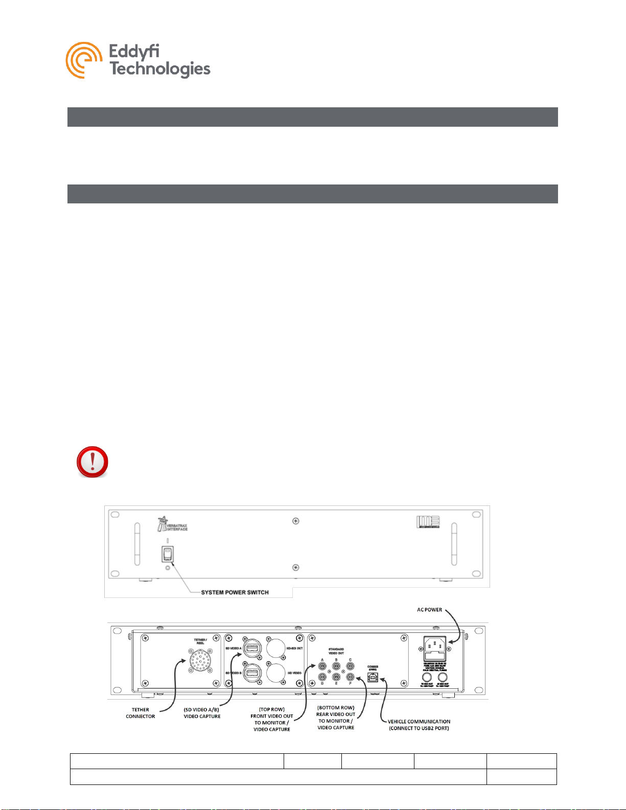
System Power
Power Requirements
The VT100™ is operated through an ICON™ Portable Controller or Interface Box. The interface box
provides power to the tether and vehicle.
Power Input: 100 –240 VAC, 50 / 60 Hz, 5 A.
Generators / Inverters
If powering the system from a generator or inverter, refer to that unit’s operating manual for
recommendations on continuous and peak load ratings. These power sources may apply a reduced
output rating based on electrical load and environmental temperature. Remember to include the power
needs of any other connected devices (external monitors, recording devices, lighting, etc.) when selecting
a generator or inverter.

VT100 Vertical Crawler™
Document: UMAH000514.docm
Revision: A14
Created by: PJ
Date: 05 Dec 2019
3029669-A14
Source Location: C:\ePDM\ISLEng\products\ah-versatrax100\manuals\UMAH000514.docm
Page 9 of 28
User Manual

VT100 Vertical Crawler™
Document: UMAH000514.docm
Revision: A14
Created by: PJ
Date: 05 Dec 2019
3029669-A14
Source Location: C:\ePDM\ISLEng\products\ah-versatrax100\manuals\UMAH000514.docm
Page 10 of 28
User Manual
ICON™ Portable Controller Connection
The ICON™ Portable Controller supplies power to the tether and vehicle. It provides a communication
interface to the vehicle. It also provides video reception and distribution.
Refer to the Controller Setup section of the ICON Portable Controller User Manual for more information.
Interface Box Connection
To set up an PC based control system with an Interface box, do the following;
Set-up:
1. Connect the interface box to AC power using an equipment power cord.
2. Connect the tether (or reel deck cable).
3. Connect the communication port to the control computer using a USB cable.
4. Connect video equipment as needed (monitors, recording devices, etc).
a. Front camera: Top row RCA jacks A, B, C.
b. Rear camera: Bottom row RCA jacks D, E, F.
The interface box may be ordered with optional features such as video capture to USB or video format
conversion. Additional connectors may be present on the rear center panel of the enclosure.
1. Connect SD Video A port to control computer using USB3 cable for front camera video capture.
2. Connect SD Video B port to control computer using USB3 cable for rear camera video capture.
IMPORTANT: USB3 cables are required for video capture (SD VIDEO A / B) to maintain video
quality.

VT100 Vertical Crawler™
Document: UMAH000514.docm
Revision: A14
Created by: PJ
Date: 05 Dec 2019
3029669-A14
Source Location: C:\ePDM\ISLEng\products\ah-versatrax100\manuals\UMAH000514.docm
Page 11 of 28
User Manual
Vehicle and Tether Connection
It is important that the tether be properly connected to the vehicle –otherwise damage to the system may
result.
1. Connect the vehicle end of tether to the back of the integrated harness block. Visually line up the
key in the connector before mating. Fully screw down and hand-tighten the locking collar.
2. Secure the tow cable to the cable grip on the tether using the quick-link. Adjust the cable grip
position to maintain a small amount of slack tether regardless the direction the tether is pulled, as
illustrated below.
3. Verify all device whips from the harness block to their respective components are securely
connected, and the whips are free from damage.
4. Ensure any unused connectors are capped with dummy plugs to insulate and protect their
electrical contacts.

VT100 Vertical Crawler™
Document: UMAH000514.docm
Revision: A14
Created by: PJ
Date: 05 Dec 2019
3029669-A14
Source Location: C:\ePDM\ISLEng\products\ah-versatrax100\manuals\UMAH000514.docm
Page 12 of 28
User Manual
Portable Reel Setup
If your system includes a portable reel, follow these steps to operate:
1. Remove the shipping cap from the front of the case and insert the crank handle.
2. Connect the deck cable from the reel to the controller.
3. Disengage the packing brake (pull back and turn on the locking pin).
4. Make sure the friction brake is engaged - disengaging the friction brake can result in slack tether
resulting in potentially jamming the reel.
5. Unwind some tether and connect the tether to the vehicle.
6. Run the tether through the level wind as follows:
a. There is an access slot which must be opened by lifting up on the two exposed screw
heads to raise the tether support shafts.
b. Pull up on both sides of the axle on the top wheel and slide the tether beneath it - failing
to lift up on the wheel can scuff and damage the tether.
c. Make sure that the two wheels that sandwich the tether top and bottom in the level wind
are tracking properly as the tether is paid out - this tells the controller how much tether
the reel has unwound and how far your vehicle has travelled.

VT100 Vertical Crawler™
Document: UMAH000514.docm
Revision: A14
Created by: PJ
Date: 05 Dec 2019
3029669-A14
Source Location: C:\ePDM\ISLEng\products\ah-versatrax100\manuals\UMAH000514.docm
Page 13 of 28
User Manual
Mini-Reel Setup
If your system includes a Mini-Reel, follow these steps to operate:
1. Remove the Mini-Reel from the shipping case.
2. Connect the deck cable from the reel to the Video Interface and Power Supply.
3. Connect the encoder deck cable from the reel to the Video Interface and Power Supply (if
provided with Mini-Reel).
4. Disengage the shipping brake.
5. Make sure the friction brake is engaged –disengaging the friction brake can result in slack tether
resulting in potentially jamming the reel.
6. Unwind some tether and connect the tether to the vehicle.

VT100 Vertical Crawler™
Document: UMAH000514.docm
Revision: A14
Created by: PJ
Date: 05 Dec 2019
3029669-A14
Source Location: C:\ePDM\ISLEng\products\ah-versatrax100\manuals\UMAH000514.docm
Page 14 of 28
User Manual
Tether Handling
The tether is one of the most important parts of the system. It feeds power and control signals to the
system and returns data to the controller. If the tether is damaged from improper use, poor handling or an
accident, the system may become inoperable. This could lead to significant downtime, loss of production,
and avoidable costly repairs. It is encouraged to stress the importance of the tether and its use to anyone
operating or maintaining the system. For maximum tether life and reliability, we recommend the following
tether handling tips.
•Do not step on the tether
•Do not drive over the tether
•Do not bend the tether beyond its minimum bend radius
•Do not kink the tether
•Do not snap load the tether
•Avoid loading the tether whenever possible
•Always use the cable grip strain relief if applicable to your system
•Regularly inspect the tether for damage
•Regularly clean the tether
Note:
Protecting the conductors inside the tether is critical to the life and operation of the tether.
Proper tether handling and care will result in extended tether life and system reliability.
Connector Handling
Connectors are an essential part of system reliability. They should be properly maintained and cared for
to ensure long life and reliability. It is recommended to follow these steps to help prevent damage and
increase the life of connectors.
•Always put the cap back on the tether bulkhead when the tether is disconnected
•Always inspect the end of the connector prior to engaging
•Never plug in a dirty or damaged connector
•Visually align key-ways or locating pins prior to engaging the connector
•Always fully engage or tighten the connector
•Secure locking collars finger tight
•Install dummy plugs on unused connectors
•Disconnect by pulling straight, not on an angle
•Do not pull on the cable to disengage the connector
IMPORTANT: Never “Hot Plug” any connector, this will result in internal damage to the
electronics. Power down the system prior to connecting the inspection system tether.
Note:
Never use WD-40 or similar solvent-based fluids on connectors or crawlers. These will cause
the rubber parts of the connector or crawler to soften and swell rendering them inoperable.

VT100 Vertical Crawler™
Document: UMAH000514.docm
Revision: A14
Created by: PJ
Date: 05 Dec 2019
3029669-A14
Source Location: C:\ePDM\ISLEng\products\ah-versatrax100\manuals\UMAH000514.docm
Page 15 of 28
User Manual
SubConn Connector: Lubrication and Cleaning
•Periodically apply Molykote 111 silicone grease or equivalent before mating connectors
•For dry mate connections, a layer of grease corresponding to 1/10 the socket depth should
be applied to the female connector
•After greasing, fully mate the male and female connector and remove excess grease from the
connector joint
•General cleaning and removal of sand or mud on a connector should be performed using a
spray-based contact cleaner like isopropyl alcohol
Impulse Connector: Lubrication and Cleaning
•Lubricate mating surfaces regularly with 3M Silicone spray or equivalent, DO NOT GREASE
•Lubricate O-rings with Molykote 111 or equivalent
•Use dust caps to protect connectors wherever possible
•Clean connectors with soap and fresh water, rinse out with alcohol and allow connector to air
dry before using.

VT100 Vertical Crawler™
Document: UMAH000514.docm
Revision: A14
Created by: PJ
Date: 05 Dec 2019
3029669-A14
Source Location: C:\ePDM\ISLEng\products\ah-versatrax100\manuals\UMAH000514.docm
Page 16 of 28
User Manual
Vehicle Configuration
Front Camera Removal / Installation
The Spectrum 45™ and lights are held onto the vehicle using a simple clamping fixture. To remove the
camera or a light, loosen the clamping M5 x 12 mm SHCS and slide the camera or light out of the fixture
as shown below. When reinstalling, ensure the connectors and locking collars are fully engaged –make
sure to properly align the pins on the mating connectors.

VT100 Vertical Crawler™
Document: UMAH000514.docm
Revision: A14
Created by: PJ
Date: 05 Dec 2019
3029669-A14
Source Location: C:\ePDM\ISLEng\products\ah-versatrax100\manuals\UMAH000514.docm
Page 17 of 28
User Manual
Expansion Range
Base Configuration
The Versatrax100™Vertical Crawler chassis comes standard configured for 200 –300 mm (8 –12in)
pipe, the Microtracs™ are connected directly to the expansion linkages as illustrated below using the side
mounting holes. Note all tracks are connected to the linkages in the same way, whether right or left.
To reconfigure the vehicle back to the standard configuration, do the following as shown below:
1. Connect the front follower linkages using M6 x 8 mm shoulder screws with plastic spring washers
beneath the heads.
2. Connect the rear follower linkages using M6 x 8 mm shoulder screws with plastic spring washers
beneath the heads.
3. Connect the drive linkages last using M6 x 20 mm shoulder screws.
4. Connect the track connector –make sure to align the mating pins correctly.
5. Repeat this procedure for each of the other two tracks.
Track removal is the opposite of installation

VT100 Vertical Crawler™
Document: UMAH000514.docm
Revision: A14
Created by: PJ
Date: 05 Dec 2019
3029669-A14
Source Location: C:\ePDM\ISLEng\products\ah-versatrax100\manuals\UMAH000514.docm
Page 18 of 28
User Manual
Extension Brackets
To increase the operating pipe size range, 50 mm (2 in) or 75 mm (3 in) extensions brackets can be
installed onto the expansion linkages.
To install either size of extension brackets, do the following as shown below:
1. Fasten the correct sized track spacer to the spacer base using 4x M5 x 16 mm FHMS.
2. Attach the Microtrac™to the extension bracket using 4x M5 x 10 mm SHCS.
3. Attach the spacer base to the expansion linkages as detailed in the previous section.
4. Ensure there is enough cable fed through the chassis to plug in the track. Wires can generally be
secured to the long bushing on the driver linkage using a zip-tie.
5. Connect the track connector –make sure to align the mating pins correctly.
6. Repeat this procedure for each of the other two tracks.
Bracket removal is the opposite of installation

VT100 Vertical Crawler™
Document: UMAH000514.docm
Revision: A14
Created by: PJ
Date: 05 Dec 2019
3029669-A14
Source Location: C:\ePDM\ISLEng\products\ah-versatrax100\manuals\UMAH000514.docm
Page 19 of 28
User Manual
Operation
Pre-Operations Check
Before each deployment of the Versatrax™ system, ensure everything is completed on the following
checklist:
❑Check that the work area has been safely set up.
❑Check that the line voltage available at the worksite matches the equipment setup.
❑Check that power and deck cable connections are correct.
❑Check the vehicle for the following:
Check that the vehicle is in the correct configuration for the deployment.
Check the vehicle for mechanical damage to the chassis or cable harnesses which could affect its
operation.
Ensure that all fasteners are in place and secure. In particular, check the fasteners holding on
cameras, lights, tracks and tow cable.
Visually inspect the vehicle and Microtracs™ to ensure that the moving parts are free of debris and
functional. Make sure the track belt is free of debris and turns freely.
Check the tether and vehicle whips for damage.
Ensure camera viewports are clean.
Check the 801 lights are clean and operational
Check that the lead screws on the raise mechanism have been well lubricated.
❑Check the winch/reel for the following:
Check that nothing will block movement of the level wind shuttle.
Check that the tether has no loose, dangling coils. Dangling coils can propagate as the drum
rotates and have the potential to jump the drum. Take care of these before deploying the tether.
❑Power up the system and check the following:
Check for enough SSD drive space for recording.
Check record directories are set.
Check video quality and camera control functions.
Test video recording.
Test main lights.
Test track control.

VT100 Vertical Crawler™
Document: UMAH000514.docm
Revision: A14
Created by: PJ
Date: 05 Dec 2019
3029669-A14
Source Location: C:\ePDM\ISLEng\products\ah-versatrax100\manuals\UMAH000514.docm
Page 20 of 28
User Manual
Post-Operations Check
A Post-Ops inspection should be carried out after every deployment using the following checklist:
❑Inspect the tether for damage as it is reeled in.
❑Visually inspect vehicle for entrained debris or mechanical damage.
❑Test each function to ensure proper operation.
❑Clean the system by hosing it down with water at regular line pressure. Do not pressure wash. The
tracks may be cleaned off by hosing them down while running. If the system has been used in salt
water, thoroughly rinse the vehicle with fresh water right away.
CAUTION: Do not use a pressure washer to clean the camera. Very high-
pressure water can push past seals and flood the camera resulting in electrical
damage or personal injuries.
❑Take time to pack the system properly for transport away from the worksite.
❑Store the system in a dry environment.
Note: Ensuring the Versatrax™ system is always stored in good working condition will minimize
deployment time for future inspections.
ICON™ & ICON™ RPT
Vehicle control and video recording are accomplished using ICON™ graphical interface controller
software. Video playback and reporting are conducted through ICON RPT. Manuals for these two
software packages are included separately. Controls for recording and snapshot functions are kept on-
screen with the camera controls.
•ICON Manual –(Control Interface and Recording)
•ICON RPT Manual - (Reporting, Playback and Video Export)
Power-Up Sequence
Interface Box
After all wiring connections have been made, the system may be powered up. The recommended
sequence for power-up is as follows:
1. Power up the control computer and allow time for it to fully boot.
2. Switch on the Interface Box.
3. Turn on the Vehicle Power Supply.
4. Start the ICON control program.
ICON always begins with identification of attached system components (cameras, tracks, etc.). If vehicle
power is turned on after ICON is started, the system will not function until ICON is closed and restarted.
Table of contents
Other Eddyfi Technologies Analytical Instrument manuals

Eddyfi Technologies
Eddyfi Technologies PANTHER 2 User manual

Eddyfi Technologies
Eddyfi Technologies INUKTUN NANOMAG WISL00359 User manual

Eddyfi Technologies
Eddyfi Technologies PANTHER 2 User manual

Eddyfi Technologies
Eddyfi Technologies TSC U41 User manual

Eddyfi Technologies
Eddyfi Technologies INUKTUN VERSATRAX 300 User manual

Eddyfi Technologies
Eddyfi Technologies INUKTUN MINIMAG User manual