Eddyfi Technologies TSC U41 User manual

Getting Started with
TSC U41
Modernizing Subsea ACFM
User’s
Manual

ii | www.eddy.com
© Eddy NDT, Inc.
3425 Pierre-Ardouin Québec (QC)
G1P 0B3 CANADA
Eddy NDT, Inc. ACFM, Amigo, Sensu, TSC, and their associated logos are trademarks or registered trademarks of Technical Software Consultants Ltd. (wholly
owned subsidiary of Eddy NDT, Inc.) in the United Kingdom and/or other countries. Eddy Technologies reserves the right to change product oerings and
specications without notice.
2019-10-11

| i
Contents
General Precautions and Conventions
General Precautions vi
Safety Precautions vi
Conventions vii
Typographical vii
Marking and Symbols vii
Safety Indications in This Document viii
Acronyms viii
EMC Directive Compliance viii
FCC Compliance (USA) viii
ICES Compliance (Canada) viii
AS/NZS Compliance (Australia/New Zealand) ix
CE Compliance (EU) ix
Maritime Environment Compliance ix
Calibration and Warranty Seals ix
Limited Warranty x
Copyrights x
System Overview
Introducing the U41 System 2
What is in the Box 2
Optional Accessories 2
System Hardware Setup 3
Overview 3
Setup for Diver 4
Setup for ROV 5
Conguring the communications 8
Alternative LAN topologies 8
U41 subsea bottle network settings 9
Topside Unit network settings 10
Testing network settings 10
Operation with ROV 11
U41 subsea bottle to Topside Unit protocols 11
Topside Unit conguration 11
U41 subsea bottle conguration 12
The Subsea Bottle
Introduction to Subsea Bottle 16
Specications 17
General specications for Model D, DA and R 17
Connectors 18
Umbilical 18
Pinout 18

ii | www.eddy.com
Probes 19
Probe connection 19
Maintenance of the subsea bottle 19
Connectors 19
Instrument and Cables 19
The Topside Unit
Introduction to the topside unit 22
Safety Trip device 23
Extension cord 23
Specications 23
General specications 23
Environmental specications 23
Connectors 24
Umbilical 24
Maintenance of the topside unit 27
Cleaning instructions 27
Assist3 Software
Introduction to Assist3 software 29
Backstage 29
General 30
Job Details 30
Select Probe 32
File Transfer 33
Start/Resume 33
Documentation 34
Preferences 34
System 34
Frontstage 37
Layout 37
Pinning side and bottom tabs 38
Information bar and warnings 39
Home ribbon 40
Scanning ribbon 41
Conguring Markers 42
Origin Dialogue Box 43
Replay Ribbon 44
Size 45
Defect List Box 46
Adding a Region 47
Regions List Box 47
Creating an Automated Report 48
Layout ribbon 49

| iii
Manipulating C-scan Appearance 52
Keyboard shortcut keys 52
Updating and upgrading the software 54
Method 54
Troubleshooting
Safety device trips 58
Figures
Figure 1-1 System hardware connections 3
Figure 1-2 Diver setup 4
Figure 1-3 ROV setup 5
Figure 1-4 ROV setup - power and communication taken from ROV 5
Figure 1-5 ROV Connections 6
Figure 1-6 LAN topologies 8
Figure 1-7 Software - Subsea bottle conguration 9
Figure 1-8 Software - Subsea bottle Ethernet conguration 9
Figure 1-9 Software - Subsea bottle IP mode conguration 9
Figure 1-10 Software - Topside unit conguration 10
Figure 1-11 Software - Topside unit conguration 10
Figure 1-12 Software - Topside IP mode conguration 10
Figure 1-13 Software - Test network settings 11
Figure 1-14 Operation with ROV - Topside conguration 11
Figure 1-15 Operation with ROV - Topside conguration 12
Figure 1-16 Operation with ROV - Topside conguration 12
Figure 1-17 Operation with ROV - Subsea bottle conguration 12
Figure 1-18 Operation with ROV - Subsea bottle conguration 13
Figure 1-19 Operation with ROV - Subsea bottle conguration 13
Figure 1-20 Operation with ROV - Subsea bottle conguration 14
Figure 1-21 Operation with ROV - Subsea bottle conguration 14
Figure 2-1 U41 bottle - side view 17
Figure 2-2 U41 bottle - top view 17
Figure 2-3 Umbilical connector 19
Figure 3-1 Topside unit 23
Figure 3-2 Topside unit - umbilical connector 25
Figure 3-3 Power in connector 26
Figure 3-4 Power out connector 26
Figure 3-5 Ethernet connector 27
Figure 4-1 Backstage view: General 31
Figure 4-2 Connect /disconnect 32
Figure 4-3 Select probe 33
Figure 4-4 View imported probes 33

iv | www.eddy.com
Figure 4-5 Backstage view: Documentation 35
Figure 4-6 Backstage view: Preferences/System 35
Figure 4-7 Company logo 36
Figure 4-8 Backstage view: Preferences/Display 37
Figure 4-9 Backstage view: Help 37
Figure 4-10 Frontstage layout 38
Figure 4-11 Frontstage screen 38
Figure 4-12 Pin tabs 39
Figure 4-13 Information bar and warnings 40
Figure 4-14 Home Ribbon 41
Figure 4-15 Coating thickness dialogue box 41
Figure 4-16 Scanning ribbon 42
Figure 4-17 Marker setup dialogue box 43
Figure 4-18 Origin dialogue box 44
Figure 4-19 Row Visibility Tab 44
Figure 4-20 Analysis ribbon 45
Figure 4-21 Replay Ribbon 45
Figure 4-22 Sizing 46
Figure 4-23 Defects list box 47
Figure 4-24 Adding a region 48
Figure 4-25 Regions list box 48
Figure 4-26 ACFM Page Report 49
Figure 4-27 Layout ribbon 50
Figure 4-28 Standard view 50
Figure 4-29 Layout 2 51
Figure 4-30 Layout 3 51
Figure 4-31 Layout 4 52
Figure 4-32 Layout 5 52
Figure 4-33 Keyboard Shortcuts 54
Figure 4-34 Launching the Setup wizard 55
Figure 4-35 Accepting the license agreement 55
Figure 4-36 Installing the software 55
Figure 4-37 Finishing the installation 56
Figure 4-38 Finish the installation 57

General Precautions
and Conventions

General Precautions and Conventions
vi | www.eddy.com
General Precautions
The following safety precautions are to be observed at all times when using U41®.
Make sure that you review them before turning on the system.
Keep this document in a safe place for future reference.
Carefully follow the installation and operation procedures detailed herein.
Respect the safety warnings on the instrument and in this document.
U41 should only be used by certied personnel.
When transporting U41, it is your responsibility to make sure that you apply the safety
precautions dictated by the relevant local governing bodies.
Always connect the power supply to a properly grounded receptacle, extension cord, or
power bar. Grounding a single conductor of a two-conductor outlet is not sucient
protection for U41.
Only connect the system to a power source corresponding to the type indicated on the
rating plate.
If you use the system in a manner that deviates from the one specied by Eddy, the
protection provided on the equipment may be rendered null and void.
Do not use substitute parts or perform unauthorized modications to the system.
Service instructions, when applicable, are intended for trained service personnel only.
Always make sure that the system is unplugged from any power supply before servicing.
To avoid a dangerous electric shock, do not perform any service on the system unless
trained to do so. If you encounter any problems or have questions regarding this system,
contact Eddy Tech-nologies or an authorized Eddy Technologies representative.
Safety Precautions
Observe the following safety precautions scrupulously when using U41.
The safety of operators and divers was paramount in the design and implementation of the U41
system. Beyond the passive design features which provide industry standard levels of electrical
safety, additional AC and DC safety trip devices have been included to further protect operators
and divers from potential failures and damage to the electrical system.
The system should never be used if the devices are missing, have been disabled or repeatedly
trip.
These devices should be tested every time that the system is rst powered on.
Read section Safety Trip device for more information on the integrated safety device.
General Precautions and Conventions
| vii
Conventions
Typographical
The following typographical conventions are used throughout this document:
Italic
Used for le names and paths.
Bold
Used to indicate menu items, named user interfaces, and place emphasis on specic words or
phrases. Items in bold type are capitalized to reect the actual interface.
SMALL CAPITALS
Used to indicate instrument interface indications.
Marking and Symbols
The following symbols appear on the instrument and pertain to safety regulations that should
be carefully observed:
This label is used as a general warning sign. It indicates that you should refer to this
user’s guide to obtain the necessary information for proper protection of the
instrument and its users.
This label is used to indicate high voltage. It draws your attention to the presence
of hazardous voltages (within the product enclosure or accessible externally) that
may constitute a risk of electric shock to persons. Always refer to the user’s guide
to ensure proper protection and safety.
The RoHS compliance logo signies that this product complies with the Restriction
of Hazardous Substances directive 2002/95/EC. This directive restricts the use of
lead, mercury, cadmium, hexavalent chromium, polybrominated biphenyl, and
polybrominated diphenyl ether in certain classes of electrical and electronic units
as of July 1, 2006.
This label acts as a reminder that you should dispose of this system in accordance
with your local Waste Electrical and Electronic Equipment (WEEE) regulations. This
system was manufactured to the high-quality standards of Eddy to ensure safe
and reliable operation when it is used as stated in this document. Due to its nature,
this instrument may contain small quantities of substances known to be hazardous
to the environment and to human health if released in the environment. As such,
systems falling under WEEE regulations should not be disposed of in the public waste
stream.

WARNING!
CAUTION
General Precautions and Conventions
viii | www.eddy.com
Safety Indications in This Document
The safety indications in this document are intended to ensure your safety and the integrity of
the system.
Warning
The warning indication calls your attention to a procedure or a practice (or the
like) that, if performed incorrectly, can result in injury. Do not ignore warning
indications make sure that you understand the condition before proceeding.
Caution
The caution indication calls your attention to a procedure or practice (or the
like) that, if performed incorrectly, can result in material damage, loss of data,
or both. Do not ignore caution indications make sure that you understand the
condition before proceeding.
Important
Calls attention to important information in order to complete the tasks.
Note
Calls attention to an operating procedure, a practice, or the like that requires special attention.
Notes also indicate useful related information, but the parenthetical information is not
mandatory.
Acronyms
ACFM: Alternating current eld measurement
HAZ: Heat aected zone
UI: User interface
A/C: Anticlockwise/Clockwise
T: Transverse
Fe: Ferrous
EMC Directive Compliance
FCC Compliance (USA)
This equipment was tested and found to comply with the limits for a Class A digital device,
pursuant Part 15 of the FCC Rules. These limits are designed to provide reasonable protection
against harmful interference when the equipment is operated in a commercial environment.
This equipment generates, uses, and can radiate radio frequency energy and, if not installed
and used in accordance with the user’s guide, may cause harmful interference to radio
communications. Operation of this equipment in a residential area is likely to cause harmful
interference in which case you will be required to correct the interference at your own expense.
ICES Compliance (Canada)
This ISM device complies with Canadian ICES-001.
Cet appareil ISM est conforme à la norme NMB-001 du Canada.

General Precautions and Conventions
| ix
AS/NZS Compliance (Australia/New Zealand)
This device complies with Australia and New Zealand AS/NZS 4252.2 (IEC 61000-6-4) and
AS/NZS 61000-6-2 (IEC 61000-6-2).
CE Compliance (EU)
This device complies with the Electromagnetic Compatibility Directive 2014/30/UE.
Maritime Environment Compliance
This device complies with the IEC 60945 and IEC 60533.
Calibration and Warranty Seals
The calibration seal is at the back of the instrument. U41 is also equipped with a warranty seal.
Important
Broken seals void the calibration certication and product warranty.

General Precautions and Conventions
x | www.eddy.com
Limited Warranty
Eddy NDT, Inc. warrants the hardware to be free of any defects in materials or workmanship
for a period of twelve (12) months from the date of delivery, under normal use and service. These
warranties are limited to the original purchase of the product and are not transferable.
Eddy NDT, Inc. will repair or replace any product component or documentation, at its option
and at no additional charge if found defective within the warranty period. The purchaser is
responsible for returning the product to Eddy NDT, Inc.
Eddy NDT, Inc., will not be held responsible in any way whatsoever for damage resulting from
improper installation, accident, misuse, or from service or modication of the product by anyone
other than Eddy NDT, Inc., or an authorized Eddy NDT, Inc. service center.
Eddy NDT, Inc. will not be held responsible in any way whatsoever for direct, indirect, special,
incidental, or consequential damages resulting from possession, use, improper installation,
accident, service, modication, or malfunction of the product (including, without limitation,
damages for loss of business prots, business interruption, loss of business information, or other
pecuniary loss). Eddy’s total shall in no event exceed the purchase price of the applicable
item(s).
This warranty is in lieu of all other warranties, whether oral, written, expressed, or implied,
including any warranty of merchantability or tness for a particular purpose, and no other
representation or claims of any nature shall be binding on or obligate Eddy NDT, Inc.
This agreement is governed by the laws of the province of Québec, Canada. Each of the parties
hereto irrevocably attorns to the jurisdiction of the courts of the province of Québec and further
agrees to commence any litigation which may arise hereunder in the courts located in the
judicial district of Québec.
Copyrights
This document and the product and programs it describes are protected by the Copyright Act
of Canada, by laws of other countries, and by international treaties, and therefore may not be
reproduced, in whole or in part, whether for sale or not, without prior written consent from
Eddy NDT, Inc. Under copyright law, copying includes translation in other languages and
formats.
© Eddy NDT Inc., 2019
This document was prepared with particular attention to usage to ensure the accuracy of the
information it contains. It corresponds to the version of the product manufactured prior to the
date appearing on the back cover. There may, however, be some dierences between this
document and the product if the product was modied after publication.
The information contained in this document is subject to change without notice.

Chapter 1
System Overview

System Overview
2 | www.eddy.com
Introducing the U41 System
Thank you for purchasing the Eddy® TSC U41 system, the most advanced ever system for
inspecting subsea structures using the Alternating Current Field Measurement (ACFM®)
technique
The U41 is the successor to the previous generation U31 instrument and contains the following
class leading features:
3 probe connectors, to reduce time spent changing out probes,
Vastly improved electronics delivering increased speed and data resolution
Removable handle to facilitate easy probe connector access
Impact bumpers
Ability to use up to 3 umbilicals joined together (450m (1476ft) total).
The U41 is available in 4 models: 2 are for use with divers and 2 are for use with ROVs.
U41D™ - basic model for divers which uses simple twin sensor probes
U41DA™ - standard model for divers which also supports a mini-array probe for increased
productivity
U41R™ - can be integrated for use with ROVs and supports a range of array probes designed
for remote deployment
U41RDW™ - the same functionality as the U41R but in a larger pressure bottle for operation
at water depths up to 2000m
We will cover what’s in the box then take an overview of the instrument and its main functions
and application capabilities.
What is in the Box
The U41 comes with the following system components and accessories:
U41 Subsea Bottle with removable handle
Blanking plugs (2) (for unused probe connectors)
Topside Unit (dierent models for D or R versions)
Topside Unit power cable with RCD
Ethernet cable
230Vac to 110Vac transformer
Test & integration deck cable (20m (65 feet))
Function check plate
Optional Accessories
Here is a list of the optional accessories that could be included depending of the option selected.
Rugged laptop running ASSIST3. Note you may use your own laptop with the system but
you will need to download, install and license the ASSIST3 software before use.
150m Subsea umbilical cable on drum. This is used for all diver operations and for ROV
operations where the U41 subsea bottle does not have a power and communications
connection through the ROV umbilical. Note that up to three 150m umbilicals may be
joined together if required.
Topside integration whip. For ROV operations this connects the topside communications
connector to the ROV interface electronics.
Subsea integration whip. For ROV operations, this connects the subsea bottle to the ROV
for power and communications.
All these accessories are available directly from Eddy Technologies. Contact your local
sales representative or oce for more information.

System Overview
| 3
System Hardware Setup
Overview
The functional connections required for both diver and ROV operations are similar with the main
dierence being the umbilical used between the topside unit and subsea bottle: the diver unit
always uses the Eddy supplied 150m subsea umbilical whereas the ROV system may use either
the Eddy umbilical or use the ROV umbilical, as required. The connections are shown in block
diagram form below:
Figure 1-1 System hardware connections

System Overview
4 | www.eddy.com
Setup for Diver
The basic connections and setup procedure to congure the system for diver deployment is
shown below:
Figure 1-2 Diver setup
1. Ensure all mains switches are OFF.
2. Connect the topside unit to the mains supply using the RCD protected lead. If the local
supply is 230Vac then the included transformer will be required.
3. Connect the computer to the U41D topside unit, using the Ethernet cable. If the
computer needs to be powered from the mains supply, instead of running from the
internal battery, connect the mains lead to the 110V output connector on the topside
unit. For more advanced connection options, see Conguring the communications on
page 8.
4. Connect the test and integration deck cable to the topside unit and connect the main
umbilical(s) to the other end of the test umbilical. Note that up to 3 main umbilicals may
be connected in series depending on requirements.
5. Connect the main umbilical(s) to the subsea unit.
6. Connect the probe(s) to be used to the U41 subsea unit. Ensure that any probe connector
which doesn’t have a probe connected to it is tted with a blanking plug. Deploying the
bottle subsea with an exposed connector will cause severe damage to the unit.
7. Test the main cable RCD by turning ON the mains supply to the lead (with the topside
unit still switched OFF). Press the Reset button and verify that the red indicator is
showing. Press the Test button and conrm that the red indicator is removed. Press the
Reset button again and check that the red indicator reappears and remains. If this does
not function, or if during operation the RCD trips repeatedly, suspend all operations, turn
o mains supply and seek specialist advice.
8. Check to insure the 110v indicator panel is illuminated.
9. Turn on the power to the U41 system by pressing the power switch on the topside unit
panel.
10. Test the safety trip on the topside unit. Press the Reset button and verify that the blue
indicator on the power switch is showing. Press the Test button and conrm that the blue
indicator is removed and the red fault light is displayed. Press the Reset button again and
check that the red fault light is extinguished and the blue power button light reappears
and remains. If this does not function, or if during operation the safety trip trips
repeatedly, suspend all operations, turn o mains supply and seek specialist advice.
11. The subsea bottle will take approximately 20 seconds to initialise following the safety trip
tests. Switch on the computer and start the ASSIST™ software.

System Overview
| 5
12. From the Backstage screen, press the Connect button. Select the instrument from the
available list and press the Connect button on this panel. For more advanced connection
options, see Conguring the communications on page 8
13. Test the correct functioning of the system by performing function checks on all probes
connected to the bottle.
Setup for ROV
There are two main setups for deploying U41R by ROV. The rst uses the Eddy umbilical and
the subsea bottle is electrically separate from the ROV for its power and communications. An
example of this deployment is shown below:
Figure 1-3 ROV setup
In this example the same general setup as used for the diver unit is used, see Setup for Diver on
page 4
The second main method is where the subsea bottle takes its power and communications from
the ROV itself.
Figure 1-4 ROV setup - power and communication taken from ROV

System Overview
6 | www.eddy.com
Figure 1-5 ROV Connections
1. Decide on the communications protocol to be used through the ROV system.
2. Ensure all mains switches are OFF.
3. Connect the topside unit to the mains supply using the RCD protected lead. If the local
supply is 230Vac then the included transformer will be required.
4. Connect the computer to the U41D topside unit, using the Ethernet cable. If the
computer needs to be powered from the mains supply, instead of running from the
internal battery, connect the mains lead to the 110-120Vac output connector on the
topside unit. For more advanced connection options, see Conguring the
communications on page 8.
5. Connect the test and integration deck cable to the topside unit and subsea bottle.
6. Test the main cable RCD by turning ON the mains supply to the lead (with the topside
unit still switched OFF). Press the Reset button and verify that the red indicator is
showing. Press the Test button and conrm that the red indicator is removed. Press the
Reset button again and check that the red indicator reappears and remains. If this does
not function, or if during operation the RCD trips repeatedly, suspend all operations, turn
o mains supply and seek specialist advice. Note that in this conguration, the topside
unit does not provide DC power to the instrument via the umbilical, this instead comes
from the ROV supply.
7. Check to insure the 110v indicator panel is illuminated.
8. Turn on the power to the U41 system by pressing the power switch on the topside unit
panel. If the blue indicator light in the switch does not light, press the reset button in the
Safety Trip area.
9. The subsea bottle will take approximately 20 seconds to initialise. Switch on the computer
and start the ASSIST™ software.
10. Congure the communications between topside unit and subsea bottle to match the
protocol decided in step 1. See Operation with ROV on page 11. Check that the subsea
bottle can be connected to using the new protocol.
11. Power down the topside unit, remove the deck cable and secure the subsea bottle to the
ROV.
12. Temporarily connect the free end of the Eddy supplied subsea communications whip to
the ROV subsea cable, supplied by the ROV team. The power wires and the
communication protocol wires, decided in step 1, must be connected.
13. Power up the ROV port and test that the correct power voltages are present on the
bottle end of the Eddy supplied subsea whip, see Umbilical on page 18 Power down
the port.

System Overview
| 7
14. Connect the Eddy supplied subsea whip to the subsea bottle umbilical connector
15. Connect the Eddy supplied topside whip free end relevant communication wires to the
ROV topside integration port. See Connectors on page 24. Connect the other end to
the topside unit umbilical connector.
16. Connect the probe(s) to be used to the U41 subsea unit. Ensure that any probe connector
which doesn’t have a probe connected to it is tted with a blanking plug. Deploying the
bottle subsea with an exposed connector will cause severe damage to the unit.
17. Power up the topside unit and ROV port. Using ASSIST, attempt to connect to the subsea
bottle. If there is no connection, re-check the physical connections and, if using serial
protocols, try swapping Rx and Tx at one end of the ROV interface.
18. Once communications are established, function check the probe on the test plate to
ensure that data is passing reliably through the system.

System Overview
8 | www.eddy.com
Conguring the communications
Alternative LAN topologies
Connection of PC or laptop to U41 systems is usually via a standard RJ45 CAT5 style LAN cable
directly from the computer to the instrumentation. This is the default setup and conguration
is not normally required. However, if LAN conguration changes have been made since the
system was received, these may need to be undone for the original operation to function again.
Alternative congurations are available, providing benets such as using existing premises LAN
and enabling use of a single PC LAN port. The most common scenarios are shown below.
Figure 1-6 LAN topologies
Conguring these alternative networking scenarios diers between U41-D and U41-R systems.
The table below outlines the recommended settings.
Scenario System Topside Unit U41 Bottle
A U41-D --- DHCP Server
B U41-D --- DHCP Server
C U41-R DHCP Server DHCP Client
D U41-R DHCP Server DHCP Client
E U41-D or U41-R --- DHCP Server
F U41-D --- DHCP Client
F U41-R DHCP Client DHCP Client
G U41-D --- DHCP Client
G U41-D DHCP Client DHCP Client
Using the table above, follow the instructions below to congure the U41 subsea bottle and
Topside Unit network settings appropriately.
Table of contents
Other Eddyfi Technologies Analytical Instrument manuals

Eddyfi Technologies
Eddyfi Technologies PANTHER 2 User manual

Eddyfi Technologies
Eddyfi Technologies INUKTUN NANOMAG WISL00359 User manual

Eddyfi Technologies
Eddyfi Technologies INUKTUN VERSATRAX 300 User manual

Eddyfi Technologies
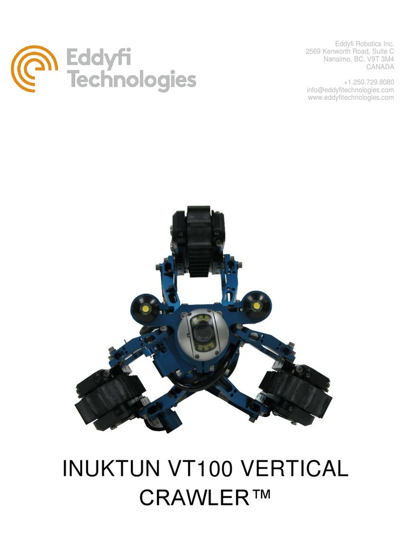
Eddyfi Technologies INUKTUN VT100 User manual

Eddyfi Technologies
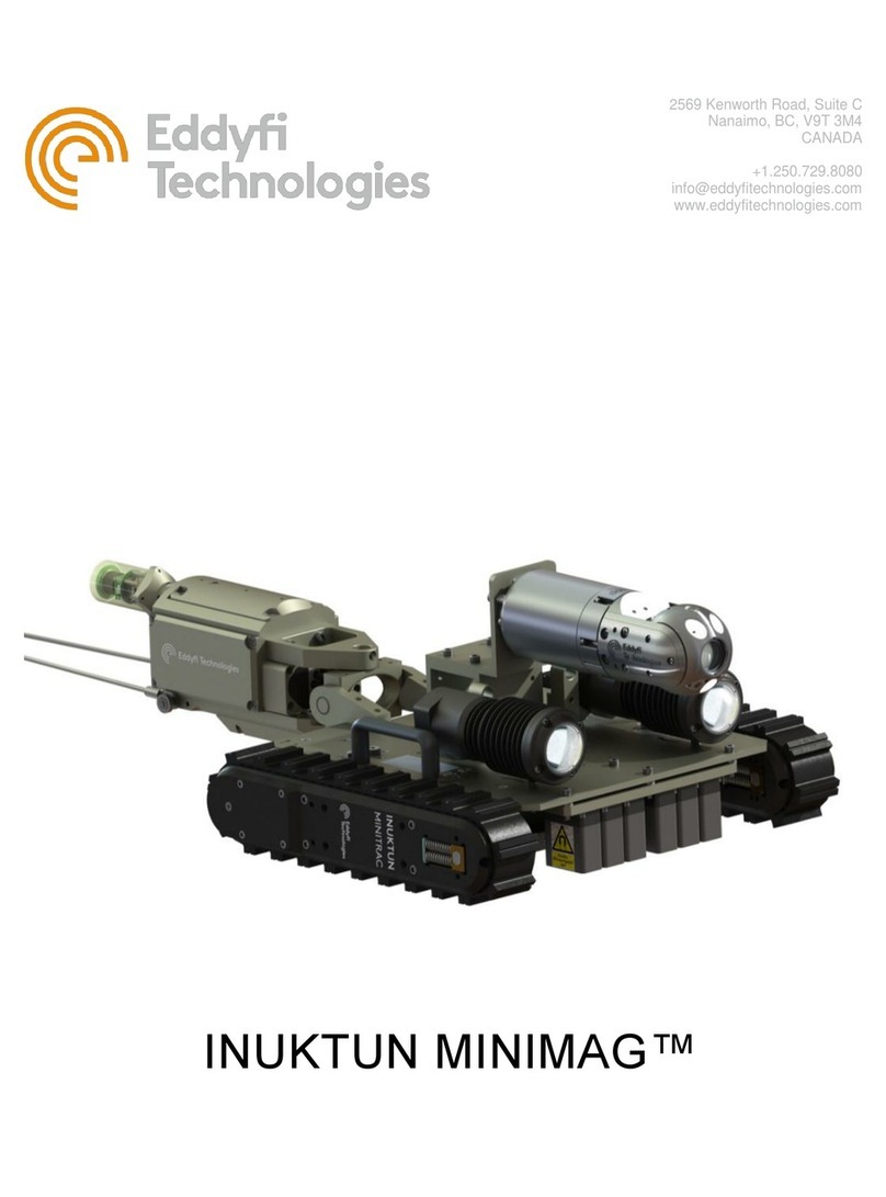
Eddyfi Technologies INUKTUN MINIMAG User manual

Eddyfi Technologies
Eddyfi Technologies PANTHER 2 User manual