Servomex 700B User manual

700B
Oxygen Analyser
Instruction Manual
Ref :00700 / 001B / 9
Order as part No. 00700 001B

NOTES

I
GENERAL SAFETY INFORMATION
Servomex oxygen analysers are sophisticated devices intended for use by qualified personnel
only. It is necessary that this manual be read and understood by those who will install, use and
maintain this equipment.
USE OF WARNING, CAUTION AND NOTE
This publication includes WARNING, CAUTIONand NOTE information where
appropriate to point out safety related or other important information.
WARNING - Hazards which may result in personalinjury ordeath.
CAUTION - Hazards which may result in equipment or property damage.
NOTE - Alerts to pertinent facts and conditions.
ELECTRICAL SAFETY WARNING
1. THE ELECTRICAL POWER USED IN THIS EQUIPMENT IS AT A VOLTAGE
HIGH ENOUGH TO ENDANGER LIFE.
2. BEFORE CARRYING OUT MAINTENANCE OR REPAIR, PERSONS
CONCERNED MUST ENSURE THAT THE EQUIPMENT IS DISCONNECTED
FROM THE ELECTRICAL SUPPLY AND TESTS MADE TO VERIFY THAT THE
UNIT IS DISCONNECTED.
3. WHEN THE SUPPLY CANNOT BE DISCONNECTED, FUNCTIONAL TESTING,
MAINTENANCE AND REPAIR OF THE ELECTRICAL UNITS IS TO BE
UNDERTAKEN ONLY BY PERSONS FULLY AWARE OF THE DANGER
INVOLVED AND WHO HAVE TAKEN ADEQUATE PRECAUTIONS.
WARNING
This 700B analyser is not suitable for use in hazardous areas without a suitable purge.

II
CAUTION
To maintain the analyser's performance only spares of suitable quality should be
used to repair this analyser. These should be obtained from either Servomex, its
associated companies or local agents.
NOTICE
Informationinthismanualisintendedonlytoassistourcustomersintheefficientoperationofour
equipment. Useofthismanualforanyotherpurposeisspecificallyprohibitedanditscontentsare
not to be reproduced in full or part without prior approval of Group Marketing Department,
Servomex plc, Crowborough, Sussex, England TN6 3DU.
RETAIN THIS MANUAL FOR FUTURE REFERENCE
The 00700B Oxygen and Combustibles Analyser complies with the European Community
“Electromagnetic Compatibility Directive”89/336/EEC by the application of the following:
A Technical Construction File No. 00700-P-004-1 dated 20.11.95 and
Test Reports No. 5044/9Y7 and 5044/9N8 issued by:
ERA Technology Ltd, Cleeve Road, Leatherhead, Surrey, KT22 7SA
The 00700B complies with the European Community “LowVoltage Directive” 73/23/EECand the “CE
Marking Directive”93/68/EEC and are rated in accordance with:
IEC664 for “Installation Category II”which is characterised as being local level (i.e. not
distribution level), appliances and portable equipment with over-voltage
impulse withstand up to 2500V.
The 00700B is CE marked (when fitted with external mains filter)for the European Community
“Electromagnetic Compatibility Directive”89/336/EEC only. It also complies with the transitional
arrangements of the European Community “ATEX Directive”94/9/EC.

III
700B OXYGEN ANALYSER
INSTRUCTION MANUAL CONTENTS
SECTION
1 INTRODUCTION
2 ANALYSER DESCRIPTION
3 INSTALLATION
4 OPERATION
5 MAINTENANCE
6 FUNCTIONAL DESCRIPTION AND SPECIFICATION
7 RECOMMENDED SPARES AND PARTS LIST
APPENDICES
APPENDIX
1 INTERCONNECTIONS - OXYGEN ONLY
2 INTERCONNECTIONS - OXYGEN AND COMBUSTIBLES
3 CABLE SCHEDULES
4 PURGE DETAILS

IV
NOTES

1.1
SECTION 1 : INTRODUCTION
LIST OF CONTENTS
SECTION PAGE
1.1 INTRODUCTION TO 700B ..................................................1.3
1.2 ANALYSER OVERVIEW ....................................................1.3
1.2.1 Product Identification ................................................1.3
1.3 HAZARDOUS AREA USE ..................................................1.4
1.4 OPTIONS ...............................................................1.4

1.2
NOTES

1.3
SECTION 1 INTRODUCTION
1.1 INTRODUCTION TO 700B
This manual provides descriptive information, installation and maintenance instructions for the
Servomex 700B combustion gas analysers.
It is divided into the following sections covering :
Section 1 Introduction to the 700B
Section 2 Description of the analyser, its operating principle and options
Section 3 Installation of the analyserand user connections
Section 4 Operating instructions
Section 5 Maintenance, fault diagnosis and repairs
Section 6 Functional description and specification
Section 7 Recommended spares and parts lists
1.2 ANALYSER OVERVIEW
TheServomex700BZirconiaOxygenanalysermeasurescombustionandsimilargasestoprovide
ananalysisofoxygenconcentration. Wheretherelevantoptionisfitted, indicationofthelevelof
unburned combustibles is given.
The system comprises two units, a sensor head and a control unit with display and keypad.
Acomprehensiverangeofsampleprobesandfiltersisavailabletoenabletheanalysertobeused
inawiderangeofapplicationsandprocessconditions,includingsamplegas temperaturesofup
to 1800OC (3200OF). It can be adjusted to operate on all common supply voltages and
frequencies.
1.2.1 Product Identification
The individual units of the analyser (sensor headand control unit)all have serial numbers. The
serialnumber of the sensorheadwill befoundin thecentreof thesensorhead cover. It is in the
form714/XYZ/NNNwhere714isthemodelnumberofthesensorhead,XYZisthemodelvariant
and NNN is the serial number.

1.4
The serial number of the control unit will be found on a label attached to the inside of the door.
Itisoftheform722/NNNwhere722isthemodelnumberofthecontrolunitandNNNistheserial
number.
A label identifying the analyser as a whole is also fixed to the control unit. This label has the
following information:
Identification number e.g. 807387
Software e.g. 722/652/2
Date tested
Picture code
When ordering spare parts it will assist if the identification number and the serial number of the
relevant unit are quoted.
1.3 HAZARDOUS AREA USE
The standard unpurged 700B is suitable only for use in safe areas.
The 700B control unit and sensor head for installation in hazardous areas may also be purged.
1.4 OPTIONS
Optionsavailableincludeisolatedanalogueoutputandalarms,adatalink,facilitiesforcalculating
anddisplayingfluegastemperatureandcombustionefficiency(usinganexternalthermocouple).
Theanalyserrequiresasupplyofcompressedairtoaspiratethesample. Arangeofairregulator
sets are available.

2.1
SECTION 2 : ANALYSER DESCRIPTION
LIST OF CONTENTS
SECTION PAGE
2.1 INTRODUCTION ..........................................................2.3
2.2 CONTROL UNIT DESCRIPTION .............................................2.3
2.2.1 Keypad...........................................................2.3
2.2.2 Display ...........................................................2.3
2.2.3 ControlUnitFunctions ...............................................2.4
2.3 SENSOR HEAD DESCRIPTION ..............................................2.5
2.4 AIR REGULATOR UNITS ...................................................2.7
2.4.1 Oxygen Analyser ...................................................2.7
2.4.2 Oxygen and Combustibles Analyser .....................................2.7
2.4.3 Oxygen and Combustibles Analyser with Auxiliary Air and Calibration ..........2.7
2.5 MOUNTING FLANGE ......................................................2.8
2.5.1 Welded Flange .....................................................2.8
2.5.2 Bolt-On Flange .....................................................2.8
2.6 PROBE TUBES ...........................................................2.9
2.7 OUTPUTS AND ALARMS ...................................................2.9
2.7.1 Standard Outputs ...................................................2.9
2.7.2 Isolated Oxygen and Combustibles Output Card ...........................2.9
2.7.3 Isolated Oxygen Output and AlarmCard .................................2.9
2.7.4 DataLink ........................................................2.10
2.7.5 Temperature and Efficiency Card ......................................2.10
LIST OF ILLUSTRATIONS
FIGURE PAGE
2.1 AnalyserBlockSchematic...................................................2.4
2.2 Sensor Head Flow Schematic ................................................2.6
2.3 Flow Schematic - AirSupply and Calibration Unit .................................2.8

2.2
NOTES

2.3
SECTION 2 ANALYSER DESCRIPTION
2.1. INTRODUCTION
The analyser comprises two separate units, thesensor head and the control unit, which may be
mounted up to 300m apart. Refer to Appendix 3.
Thesensorheadmountsdirectlyonto the fluewitha probetubewhich projectsthrough the duct
wallintotheprocessgastodrawoutasampleforanalysis. Itcontainsazirconiacellto measure
theoxygencontentofthefluegasesandaflowsensortomonitortheflowofthesamplegas. An
optional combustibles sensormay also be fitted. The power forthe sensor head is derived from
the control unit.
The control unit, which is remote from the sensor head, provides powersupplies to the sensors
and heaters. It also processes the outputsignals fromthe measuring cellsto provide the output
indications, and houses the option cards to provide additionalfeatures.
2.2 CONTROL UNIT DESCRIPTION
The control unit houses the power supplies, microprocessor, membrane keypad,display, option
cards, output circuits for the system and the combustibles electronics, when specified. The unit
is designed for surface mounting.
The basic control unit contains two circuit boards. The first is mounted on the door and carries
the membrane keypad and the display with associated electronics.
The second board is the main motherboard and is mounted on a chassis in the rear of the
enclosure. It carries the analogue input and output circuits and, at the right hand, the power
supply for the electronics and the low voltage ac powerfor the zirconia cell heater.
Thesupplyvoltageismonitoredby themicroprocessor. Ifthevoltagefallstoalevelat whichthe
electronicscannotoperate,theinstrumentputs itselfinasafe conditionandthenceasesnormal
operation. When possible, in this condition a 'POWER FAIL' message is displayed. Normal
operation is automaticallyresumed when sufficient voltage is restored.
2.2.1 Keypad
The keypad is used to control the display and operating parameters of the system. Certain
functions,whichaffecttheoutputandcontrolsignalsfromtheunit,areaccessibleonlybyentering
a password.
2.2.2 Display
The unit has a 12 character alphanumeric display. Normally this displays the oxygen and/or
combustiblecontent of the sample; but, when the instrumentis being calibratedor the operating
parametersarebeingadjusted,itdisplayspromptmessagestoensurethatthecorrectsequence
of operations is carried out. It will display messages which permit diagnosis of faults and

2.4
interrogation of alarms which may arise within the analyser. If the temperature and efficiency
option is fitted, flue gas temperature and combustion efficiency can be displayed.
2.2.3 Control Unit Functions
The main board of the control unit inputs the analogue signals from the sensors via a 12bit A to
D converter. The microprocessor processes the signals, provides temperature control of the
zirconia cell and the sample block and generates outputs to the display, alarms and analogue
outputs.
Data is stored in a permanent memory (EEPROM)which does not require battery back-up.
The programme run by the microprocessor is monitored by a Watchdog. In the event of a
malfunction a microprocessor reset is automatically performed by the Watchdog.
Ifeitherthe zirconiacellorsampleblocktemperaturegoes outof limitsformorethan 30minutes
the control unit shuts down and generates a 'SYS. FAIL' message to protect the analyser and
indicate a fault.
Figure 2.1 Analyser Block Schematic

2.5
An interface adaptor card, to which option cards may be plugged, is fitted when options are
specified. Up to 6 cards may be fitted to the interface adaptor card. See Figure 2.1.
Whentheoptionalcombustiblessensorisfitted,itstemperatureiscontrolledindependentlybythe
combustibles card which occupies two positions on the interface adaptor card.
2.3 SENSOR HEAD DESCRIPTION
The sensor head is designed for industrial use in process plants. It is designed to IP55 (NEMA
4) to withstand dust concentration and spray water.
Parts containing sample gas within the sensor head are maintained at 200oC (392oF) to avoid
sample condensation.
The oxygen and optional combustible sensors are mounted external to the flue. Sample gas is
drawn through the sensors by means of an air driven aspirator.
The oxygen content of the sample is measured with the well-proven Servomex zirconia cell.
TheoptionalcombustiblessensorisaConstantTemperatureCatalytic(CTC)sensorandisused
to determine the level of combustible gases (expressed as carbon monoxide) in the sample
stream.
Theoxygenandcombustiblessensorsareindependentlytemperaturecontrolled. Theoperating
principles of the sensors are described in Section 6.
In order to provide a reading of combustible gases in the sample under reducing conditions,
Servomex has adopted a parallel arrangement of the sensors. In this arrangement an optional
supplementaryairbleedtothecombustiblessensorcanbeprovidedtoensurecompleteoxidation
of the combustible gases when the oxygen content of the sample gas is low.
Itisrecommendedthatexhaustgasesarereturnedtotheprocess. Someprobeoptionsdoallow
venting to atmosphere.
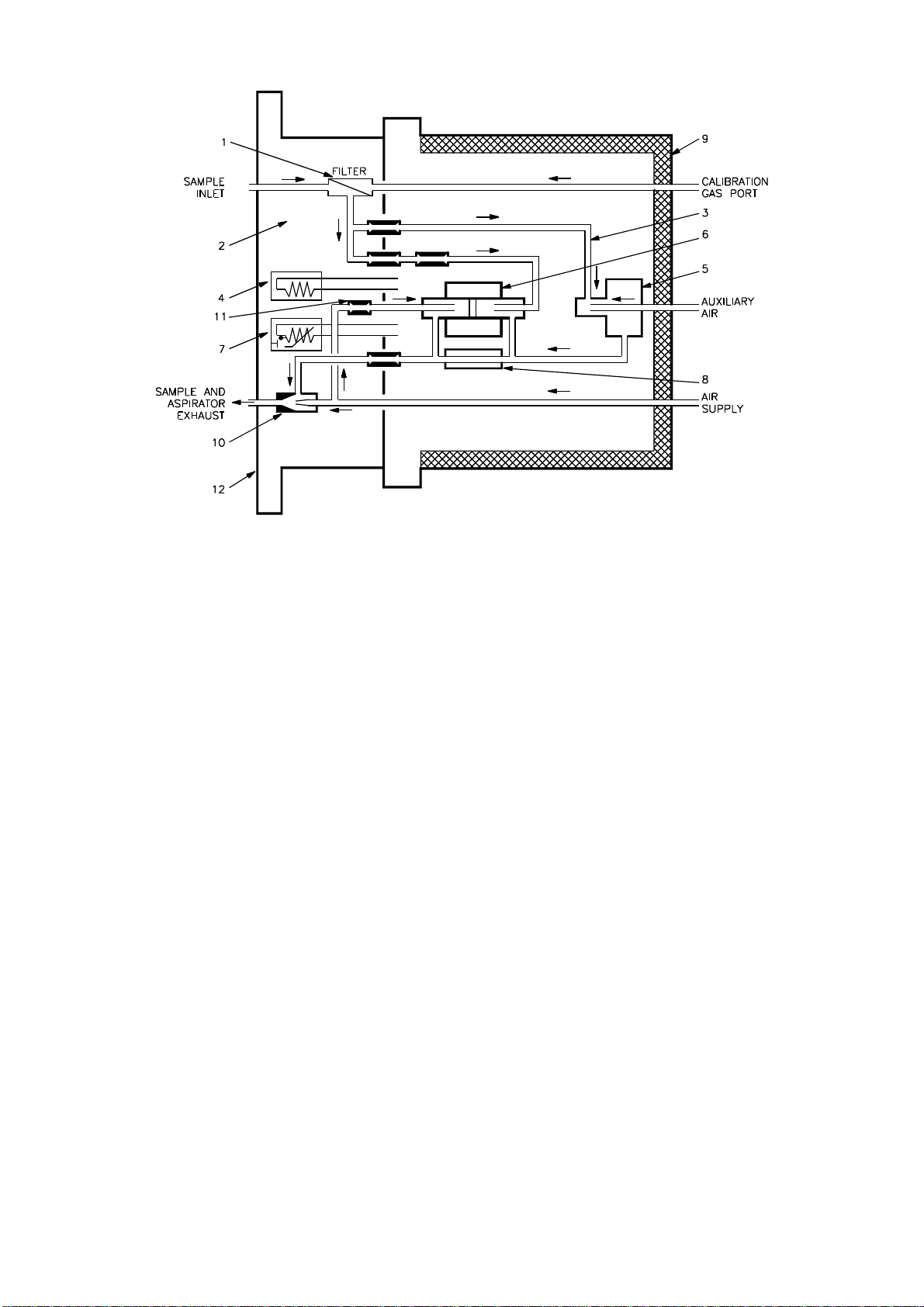
Referring to Figure 2.2, the following description assumes that the combustibles option is fitted.
Theaspirator(10),operatedbycompressedair,drawssamplegasfromtheflueataflowofabout
300ml/min through the filter (1). The flow isdivided inthe ratio2:1 by the restrictors (3). These
restrictors and the one down stream of the oxygen measuring cell (6) also act as flame trapsto
isolate the hotcell from the process. This prevents the possibility of an explosion should a high
concentration of flammable gases be present in the sample at high oxygen levels.
2.6
Figure 2.2 Sensor Head Flow Schematic
A small portion of the aspirator air supply is tapped via the capillary restrictor/flame trap (11) to
provide a reference oxygen level in the reference side of the oxygen measuring cell (6).
Thetotalsamplegasflowismonitoredbytheflowsensor(8)whichinitiatesanalarmifthesample
flow drops below a preset level.
Sensor (5) is fitted to measure the combustibles content of the sample. Should there be
insufficient air in the sample to ensure complete combustion of the gases an auxiliary air supply
can be fitted. The auxiliary air flow rate, which has to be strictly controlled, is mixed thoroughly
with the sample gasbefore being presented to the combustibles sensor in orderto obtain a true
reading.
If combustibles analysis is not required, the sensor is replaced by a bypass tube to maintain the
same sample flow rate.
The sample block (2)is heated by the cartridge heater(4). The block temperature is monitored
by the temperature sensor(7).
The sensor head is mounted onto the flue by the flange (12).
The insulated cover (9)reduces the heat loss fromthe sensor head.
Calibration gases are introducedvia the calibration gasport at apressure abovethat in the flue.
Thecalibrationgas port,filterandprobetubeare arrangedin-lineso that the probe tube may be
tested without the need to demount the sensorhead from the process.

2.7
Theterminalblockonthesensorheadcontainsvoltageselectorlinkstoadapttheunittothelocal
supply voltage.
2.4 AIR REGULATOR UNITS
Threetypesofairregulatorunitare availablewhicharedesignedfordifferentapplications. Inall
cases inlet air pressure should be in the range 0.6 - 6 barg (10 - 100 psig).
2.4.1 Oxygen Only Analysers
This is a simple air pressure regulator which controls the airpressure applied to the aspirator in
the sensor head to within ± 70mbarg (±1psig).
2.4.2 Oxygen and Combustibles Analysers
When the combustibles content of a sample is being measured, the output of the combustibles
sensorisproportionaltothequantityofcombustiblegasflowingthroughthesensor. Thisdepends
on two factors:
a) The absolute concentration of combustible components in the sample.
b) The flow rate of the sample.
Therefore, to obtain a stable measurement, it is necessaryto control the flow rate of the sample
accurately. Thisisachievedbycontrollingtheaspiratorsupplypressurecloselyusingaprecision
regulator which maintains thispressure to within ±7mbarg (±0.1psig)
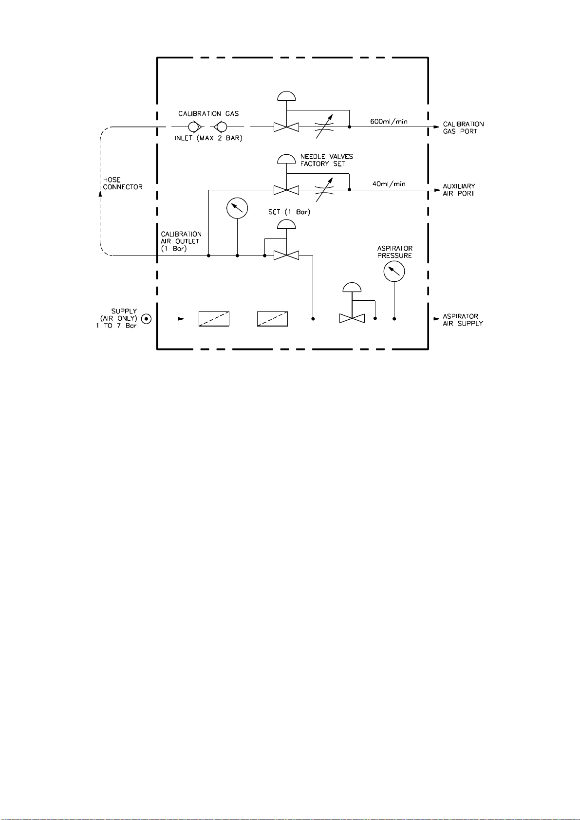
2.4.3 Oxygen and Combustibles Analyser with Auxiliary Air and Calibration Unit
In those cases where the concentrationof combustiblegases meansthat there isan insufficient
quantity of oxygen available in the sample stream to perform the combustibles analysis, an
auxiliaryairsupplyisnecessarytoobtainatruemeasurement. Thisenablesmeasurementofup
to 5% carbon monoxide in the absence of oxygen in the process.
Astheoutputofthecombustiblesdetectordependsuponrateofairflowthisunitregulatestheair
flow to tight tolerances. It also includes facilities for introducing calibration gases.
2.8
Figure 2.3 Flow Schematic - Air Supply and Calibration Unit
2.5 MOUNTING FLANGE
The flue has to be fitted with a flange for attachment of the sensor head.
The standard flanges are suitable for a skin temperature up to 350oC (662oF). Flanges with a
stand-off are used for skin temperatures of 350 -500oC (662 - 932oF).
Two mounting flange options are available for both standard and stand-off flanges.
2.5.1 Welded Flange
This flange maybe either welded directly on tothe surface ofthe flue when itis flat,or to ashort
length of 4 inch O.D. tube when the flue surface is curved.
2.5.2 Bolt-On Flange
This flange isfor bolting to the flue wall when welding is impracticable.

2.9
2.6 PROBE TUBES
A wide range of probe tubes, with or without filters, is available. Servomex can advise on the
choice of probe for a specific application. Standard probes include:
a) Unsupported filter probes up to 1 metre long for a maximum flue gas temperature of
500oC (932oF).
b) Supportedfilterprobesupto3metreslongforamaximumfluegastemperatureof500oC
(932oF).
c) High temperature alloy probes up to 1m length for a maximum flue gas temperature of
1000oC (1832oF). Longer probes can be used at temperatures below1000oC, 1.5m up
to 800oC, 2m up to 750oC. External filters can be fitted to these probes to suit dusty
applications.
d) Ceramic probes up to 1.5 metres long for maximum flue gas temperatures of 1600oC
(2912oF).
e) Ceramic probes up to 1.5 metres long for maximum flue gas temperature of 1800oC
(3272oF).
2.7 OUTPUTS AND ALARMS (See Section 6 for specifications)
The standard analyser hasnon-isolated analogue output available from themain board. Option
boards can be fitted to give isolated outputs and alarms for gas concentration and analyser
status/fault.
2.7.1 Standard Outputs
Thestandardoutputsforoxygen,andcombustiblesiffitted,arenon-isolatedandcanbeselected
via the keypad as 0-20 mA or 4-20mA and 0-10V or 2-10V for oxygen ranges of 2.5, 5, 10 and
25% and combustibles ranges of 0.25, 0.5, 1 and 5%
2.7.2 Isolated Oxygen and Combustibles Output Card 00722921
Thisoptioncardprovidesisolatedcurrentoutputsfortheoxygenandcombustiblesignals.These
outputs can be selected via the keypad as 0-20 mA or4-20 mA. See Section 6.
2.7.3 Isolated Oxygen Output and Alarm Card 00722911
Thisoption card providesan isolated currentand voltage output for oxygen level and a volt free,
normallyclosed contact, to open onalarm, foroxygen level or analyser fault. The output can be
selected via the keypad as 0-20mA or 4-20 mA and 0-10V or2-10V. See Section 6.

2.10
The analyser fault alarm will warn of the following:
Low sample flow
Sensor head under or over temperature
Oxygen cell under or over temperature
Oxygen cell output out of limits
In addition to the volt-free contact alarmthere are three non-isolated alarms for:
Oxygen high
Oxygen low
Analyser fault (alarms as above)
2.7.4 Data Link 00722913
The data link card option enables full duplex communication between the control unit and a
computer or dumb terminalvia isolated RS232, RS423 or 20mA current loop. The Baud rate is
userselectablebetween300and9600Bauddependentontheinterfaceandcabledistance. Data
display modes are selectable. Section 6 gives fulldetails of data protocol.
2.7.5 Temperature and Efficiency Card 00722914
This option card provides non-isolated outputs for both combustion efficiency and flue gas
temperature (requires the installation of thermocouple in the flue), or when requested from the
keyboard, a display of the air inlet temperature (requires a secondthermocouple to monitor the
air inlet temperature). No electrical output is available for air inlet temperature. Where no inlet
temperature thermocouple is fitted an assumed value of ambient temperature may be entered
manually. This is necessary for the analyser to performthe efficiency calculation.
The outputs can be selected via the keypad as 0-20mA or 4-20 mA and 0-10V or2-10V.
Calculation of the efficiency is according to the Siegert equation (BS 845.1972). See Section 6.
Also provided is a non-isolated output forflue gas temperature high alarm.
This manual suits for next models
1
Table of contents
Other Servomex Analytical Instrument manuals

Servomex
Servomex 2700 User manual

Servomex
Servomex DF-310E User manual

Servomex
Servomex xendos 1800 Series User manual

Servomex
Servomex DF-150E User manual

Servomex
Servomex SERVOPRO k2001 User manual

Servomex
Servomex SERVOTOUGH SpectraExact 2500 Instruction manual

Servomex
Servomex SERVOPRO 4900 User manual

Servomex
Servomex NanoTrace DF-760E User manual

Servomex
Servomex SERVOPRO Chroma User manual


