Edge Products GM Juice-Attitude CS User manual

Edge GM Juice Supplement
CS/CTS Products
Installation Instructions
READ IMPORTANT SAFETY INFORMATION IN THIS MANUAL

Edge Products ______________________________________GM Juice-Attitude CS/CTS
2
Table of Contents
IMPORTANT SAFETY INFORMATION _____________________________________ 3
SAFETY TERMS_____________________________________________________________ 3
SAFETY GUIDELINES _______________________________________________________ 3
PRODUCT REGISTRATION_______________________________________________ 4
Benefits of product registration:_________________________________________________ 4
About the Edge Juice______________________________________________________ 5
Power Levels _________________________________________________________________ 6
EGTs: What they mean and why________________________________________________ 6
The Juice Module and your Transmission_________________________________________ 7
Transmission Relearning_______________________________________________________ 7
Connecting and Installing the Juice__________________________________________ 7
Supplied Items:_______________________________________________________________ 8
Required Tools: ______________________________________________________________ 8
2001-2005 GMC Duramax 6.6L LB7 & LLY ______________________________________ 8
Power Gains _________________________________________________________ 9
2006-2007 GMC Duramax 6.6L LLY / LBZ ______________________________________ 10
Power Gains ________________________________________________________ 12
2007.5-2009 GMC Duramax LMM______________________________________________ 12
Power Gains ________________________________________________________ 15
Final Inspection _____________________________________________________________ 15
Install and Attach the EGT Probe___________________________________________ 16
Attach the EAS JAB (Juice-Attitude Bridge) __________________________________ 19
Hot Unlock Code ________________________________________________________ 23
Warranty Information ____________________________________________________ 25
LIMITED 1 YEAR WARRANTY ______________________________________________ 25
Glossary of Terms _______________________________________________________ 27
Technical Support:___________________________________________________________ 27
©2009, Edge Products Incorporated
All rights reserved.
Edge Products
1080 South Depot Drive
Ogden, UT 84404
888-360-3343
www.edgeproducts.com
Manual Version 0

Edge Products ______________________________________GM Juice-Attitude CS/CTS
3
IMPORTANT SAFETY INFORMATION
SAFETY TERMS
Throughout this User Guide (hereafter referred to as User Manual or Manual) you will see important
messages regarding your safety or the protection of your vehicle. These messages will be
designated by the words WARNING or CAUTION.
WARNING indicates a condition that may cause serious injury or death to you, your
passengers or others nearby. Pay careful attention to these Warning messages, and always comply
with them. They could save a life.
CAUTION indicates a condition that could cause damage to your vehicle. It is important to install
and operate your EDGE product in conformance with instructions in this Manual. Caution messages
alert you to particularly important things to watch for to keep your vehicle operating the way you
want it to.
The Edge product you have bought is a high-performance product. As such, it does present some
risks of which you should be fully aware. Do not use this product until you have carefully read all the
following safety information and the Owner Agreement.
SAFETY GUIDELINES
1. Do not exceed legal speed limits on public roadways. Use any enhanced speed
capabilities of this product only in closed circuit, legally sanctioned racing environments
expressly for this purpose. Loss of control from speeding on a public road could seriously
injure you, your passengers, or others on the roadway.
2. Select a position on the windshield or dashboard to mount the device where it will not
impair your view. You must be able to see the road, traffic, and pedestrians without
interference. Be sure your mounting location meets state and local laws regarding
placement of devices on the windshield or dashboard.
3. Do not operate the device while driving. Perform all adjustments or changes while
stopped. Changing a setting while under way can interfere with your attention to roadway
conditions.
4. “Stacking” performance-enhancing devices or other improper installation could cause
powertrain failure on the road. Other products may have features incompatible with your
Edge device. Follow all installation and operating instructions, and don’t stack products.
5. Some modifications may affect other parts of your vehicle. For example, if you
remove/adjust the speed limiter in your vehicle, be sure your tires and other components
are rated for the increased speeds they will have to withstand. Not doing so can lead to
loss of vehicle control. Modify the speed limiter only for use in closed circuit, legally
sanctioned racing environments, not for use on public roadways.
WARNING
Misapplication or misuse of this product could lead to a serious or fatal accident.
Comply with all safety information below, and in your vehicle owner’s manual.
Follow safety, installation and operating instructions in this User Manual to

Edge Products ______________________________________GM Juice-Attitude CS/CTS
4
6. Do not use the Performance Tests feature to break any traffic laws. Perform these tests
only where they are legal and safe.
7. Some features may not function on all vehicle models. Check a newly-installed device for
all features you intend to use. Do not rely on their working without checking first.
NOTE: Dispose of this product consistent with local codes. Return to your electronics supplier for
proper handling.
PRODUCT REGISTRATION
Please take the time to register your product. To register your product, follow the
instructions at this link. http://www.edgeproducts.com/product_registration.php
Benefits of product registration:
Your Safety – registering your product allows us to know exactly which product you have and
provide important product updates to you that improve the quality and/or safety of the product
Enhanced Features – almost all Edge products are easily updated via the internet. We are
constantly adding new features and improvements to our product that we know you will want to
enjoy
Confirmation of Ownership – provides a record in case of product loss, theft, or required warranty
work. When you call us for support our team will already have much of the information they need to
help you!
Improved Product Development – helps us better understand you (our customers) and design
products that meet your needs
Special Offers – allows us to inform you about special offers on accessories and/or new products that
fit your vehicle and enhance your driving experience
AND…
Extended Warranty Plan Opportunity – within the first 90 days of ownership, Edge offers the
option to buy a 1-year warranty extension to all customers who register their product!
All Edge modules and programmers are built to operate with OEM calibrations.
When you take your vehicle to a service center they may, by your request or otherwise,
update your vehicles calibrations. Therefore it is important that you return your
vehicle to stock before taking it in for service. Edge updates its active products (i.e.
those currently being manufactured) to work effectively with updated OEM
calibrations. However, this process can take some time as Edge is not always made
aware of calibration changes made by the OEM. In the case of discontinued products,
Edge cannot ensure that your unit will work effectively if you take your vehicle to a
dealership and you are given, by your request or otherwise, a new calibration.
Programming your vehicle may expose existing defects in your vehicle’s PCM that could
disable your vehicle. It is advised that you do not program your vehicle in remote locations
in case of vehicle failure.

Edge Products ______________________________________GM Juice-Attitude CS/CTS
5
If you have used another tuner/programmer on your vehicle, you will need to program
back to stock and remove the device before using the Edge Products Device.
Failure to return to stock may result in PCM failure or engine damage.
Note: This manual includes installation instructions to install the Juice module in
various GM model years.
1. Refer to your model Year.
2. Refer to the CS/CTS Attitude Manual for additional information.
About the Edge Juice
Congratulations on purchasing the Edge Juice module for the GM Duramax® Diesel. If you
have any questions, please contact Edge Products. We will be very happy to answer your
questions about our complete product line.
The Juice Module is an add-on Engine Control Module (ECM) for the GM Duramax®
Diesel Engine that offers additional features not available with the factory setup. Since it is
an add-on ECM, it uses all the factory data, and then enhances the factory settings to
optimize your truck’s performance. These features may include:
Engine temperature monitoring and power increase from the Juice module as engine
reaches operating temperature
Up to 6 on-the-fly selectable power settings if installing with the CS/CTS Attitude
Monitor.
Transmission slip monitoring – If any transmission slip is detected power is
decreased to prevent the transmission from slipping.
Smart power control during torque converter lockup to allow a smooth, easy torque
converter clutch lock-up
If this is your first time driving a diesel truck with a performance module, you will notice
improved fuel economy, greater performance, more power, better throttle response, passing
and acceleration!
The Juice module regulates power delivery and timing based on engine temperature for
certain models. This means that while the engine temperature is below 140° F no additional
fueling or timing is delivered. At 140° F the module begins delivering fuel. The Juice
delivers 100% of the calculated additional fuel at 160° F, and at 160° F the Juice also starts
modifying timing.
The Juice module offers a large power increase over stock throughout the rpm range, but
the power is most noticeable in the midrange rpm’s. This greatly improves drivability and
towing performance. Transmission downshifting is greatly reduced, especially while
passing or towing. If you are towing, the increased power from the Edge Juice module will
allow you to maintain speed going up a hill, keep you in a higher gear, and reduce
transmission “hunting” for lower gears.

Edge Products ______________________________________GM Juice-Attitude CS/CTS
6
Power Levels
Power level 1 is specifically designed to maximize fuel economy improvements. We
recommend level 1 or level 2 for towing applications. Use level 2 if you are towing a light
load.
WARNING Do not exceed your vehicle’s max GVWR as outlined in the vehicle’s
owner’s manual. Doing so may result in loss of vehicle control and cause bodily injury.
The remaining power levels are designed to match fueling with any additional upgrades you
may have done to your vehicle. Level 3 is as far as you should go on a stock truck and
should never be used while towing.
Level 3 is designed to take advantage of the built-in safety margins the manufacture needs
to add in order to make sure your vehicle can perform at its maximum capacity. When
driven responsibly, and used with an EGT gauge or the Attitude monitor, level 3 will not
stress the stock engine or transmission as long as you are not towing.
Levels 4 and higher are performance and race levels and are designed to be used with
upgraded drive trains. If you have modified your injectors, upgraded the transmission,
changed turbos or performed other similar enhancements, levels 4 and higher will match
fueling to the additional performance created by these upgrades.
Caution: On a stock truck, the additional power may overstress the engine and
transmission while driving in power levels 4 or higher, or at any level if you drive too hard.
We recommend that you only use level 1 or 2 while towing to keep EGT temperatures lower
and reduce transmission stress.
Power Level HP and Torque Gains
When power gains are noted, they are representative of an actual vehicle test. These gains
were measured on a Super Flow Dyno at an altitude of 4400 ft above sea level, and
represent power delivered to the rear wheels of the test truck. The only modification made
to the test vehicle was the addition of the Edge Power Juice module. Power gains may vary
somewhat on a different vehicle or in different geographic settings.
WARNING Do not “stack” non-Edge recommended modules to gain more
horsepower. They could be incompatible and result in powertrain failure or create
dangerous conditions leading to a serious or fatal accident.
EGTs: What they mean and why
EGT stands for exhaust gas temperature, and is the single most important indicator of how a
diesel engine is performing. Unlike a gasoline motor, a diesel motor will continue to make
power as more fuel is added. As more fuel is added, heat will be generated until the motor
just gets too hot and things start to melt. This is a situation you want to avoid. Exhaust gas
temperature is the ideal measurement of how hot the motor is, since temperature
fluctuations in exhaust gas are almost instantaneous. It is possible to generate excessive
EGT on a stock truck, particularly if you are towing. This is why we always recommend

Edge Products ______________________________________GM Juice-Attitude CS/CTS
7
installing an EGT gauge and why we build the CS/CTS Attitude monitor, which monitors
EGT and will automatically defuel your truck when EGTs get too high.
In our experience 1350 degrees is about as high as you want to let your EGTs go. Keep in
mind, the stress on your engine created by the heat is a function of both temperature and
time. A brief spike to 1400 that lasts a second is not that big a deal. Pulling up a hill for
several minutes at 1400 is far worse.
As you drive your vehicle in the various power settings, keep your eye on the EGTs.
Depending on how you drive and where you drive, you may find a particular power level is
more suitable to your power needs.
The Juice Module and your Transmission
The automatic transmission has a fluid-filled clutch-like device called a torque converter.
This device uses the spinning motion of the motor to drive the transmission which drives
your wheels. As the truck speed stabilizes, the torque converter engages a mechanical
connection which locks the two halves of the torque converter, so the output shaft is going
the same speed as the input shaft. This mechanical linking of the two halves is called
Transmission Lock-up. If the motor produces too much power, this mechanical lock-up
can start to slip. When this slippage occurs, the Juice module reduces the power output to
allow the transmission to function properly. This is a great feature that provides an extra
level of protection for your vehicle.
Transmission Relearning
The Allison transmission is a “Smart” transmission. That means that it pays attention to
how smoothly the transmission is changing gears, and modifies the shifting to improve
drivability. When the motor delivers more power (by adding the Juice module), the
transmission has to ‘re-learn’ how to shift. After first installing the Juice module, you may
notice rough shifting. The best way to re-teach the transmission is to set the truck in the
power level you will be using most of the time. Then set out to drive, some city, some
highway, varying the driving and the speed. A good rule of thumb would be 100 to 200
miles. Make sure that you shift through each gear 20 to 30 times. You will notice the
shifting becoming better, and your truck responding better to the additional power as you go
through the learning cycle.
Connecting and Installing the Juice
WARNING An electrical charge or battery acid can burn you. Battery gas can
explode or ignite. Take care when working around the battery. Follow instructions in the
vehicle owner’s manual for disconnecting and reconnecting a battery.
IMPORTANT: Read all Safety, Warranty, and Installation Instructions before installing
this product. Read through these instructions completely so that you understand each step
prior to installation.

Edge Products ______________________________________GM Juice-Attitude CS/CTS
8
Supplied Items:
1. Edge Juice Module
2. Harness cable set (3 assemblies)
3. Accessory package including Velcro mounting strips, wire ties and Fuse taps.
4. EGT Thermocouple Sensor Probe
Required Tools:
1. 21/64" (5/16" optional) Drill bit and Power Drill (for EGT installation)
2. 1/8" (NPT) National Pipe Tap and T-Handle/Wrench (for EGT installation)
3. 9/16, 5/8 and 5/16" (or 8mm wrench)
4. Phillips Screwdriver
Mounting the Juice Module
Notice: Use caution when inserting connector bodies. If the connector does not slide
smoothly, remove the connector, inspect the pins, and retry installation. Pull on the
connectors, not the wires, when disconnecting the engine or Juice harnesses.
The Edge Power Juice Module can mount on top of or to the side of the black plastic fuse
box cover located on the driver’s side fender. Adhere the module using the supplied Velcro,
allowing enough harness movement for removal of the box cover.
Select your year and model from the following examples to aid in installation of the
harness:
2001-2005 GMC Duramax 6.6L LB7 & LLY
The following picture shows the Edge Power Juice Module with the harness cable.
Disconnect both stock engine harness connectors by squeezing the ears on the backside of
the connector and pulling the gray lever.
These two
connectors are
used to
connect the
EGT.
This cable is
where the
Edge CS/CTS
Attitude cable
gets connects.
Edge Juice
Module
The “ T” connections
are connected to the
Main Engine Harness

Edge Products ______________________________________GM Juice-Attitude CS/CTS
9
Carefully insert the Juice "T" harness connectors between the mating stock engine harness
connectors and lock in place with the gray levers.
Power Gains
Level Horsepower Torque
LEVEL 0 0 0
LEVEL 1 40 150
LEVEL 2 60 180
LEVEL 3 75 200
LEVEL 4 90 250
LEVEL 5 125 325
LEVEL 6 (See Hot Unlock section) 150 350

Edge Products ______________________________________GM Juice-Attitude CS/CTS
10
2006-2007 GMC Duramax 6.6L LLY / LBZ
The following picture shows the Edge Power Juice Module with the harness cable. Note: If
you have a Harness with (2) “T” connectors, the 2nd T is functional and should still be
used, with both “T’s” installed.
1. Disconnect stock engine connectors by squeezing the ears on the backside of the
connector and pulling the gray lever.
Carefully insert the Juice "T" harness connectors between the mating stock engine
harness connectors and lock in place with the gray levers.
These two
connectors are
used to connect
the EGT.
This cable is where
the Edge CS/CTS
Attitude cable gets
co
nn
ects
.
This is the
turbo timer
connecter
Edge Juice
Module
This “ T” connection is
connected to the Main
Engine Harness

Edge Products ______________________________________GM Juice-Attitude CS/CTS
11
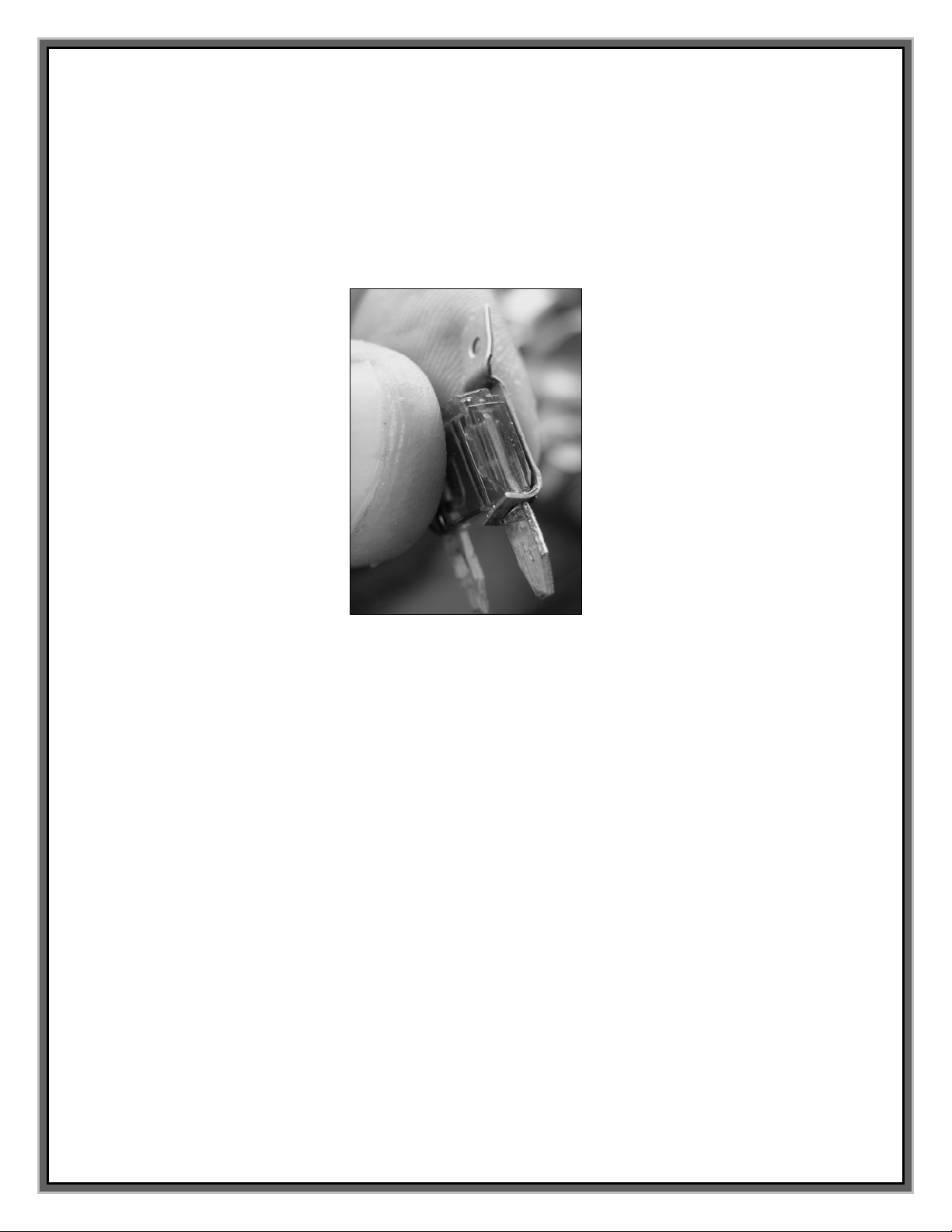
2. Route the black turbo timer wire with the red female connector end into the side of the
fuse box to connect the turbo timer. Remove the fuse and install the supplied fuse tap to
connect to the right side (side closest to the fire wall) of the 10A TBC BATT fuse (see
following pictures). Re-install the fuse and cover.
Note: The Turbo timer will not function unless the vehicle has the Attitude monitor
installed.
FUSE TAP INSTALLED ON FUSE
Note: Reference the Diesel chart inside the fuse box cover or operators manual for fuse
identification. If the wire terminal does not fit snugly, carefully squeeze the terminal that
slides over the fuse tap until it fits more securely.
Connect the turbo
timer wire to the
right side of this
fuse, using the
supplied fuse tap.
Route the wire
through side of
fuse box with
existing harness
bundle, and “fish”
through box as
shown.

Edge Products ______________________________________GM Juice-Attitude CS/CTS
12
Power Gains
Level Horsepower Torque
LEVEL 0 0 0
LEVEL 1 30 60
LEVEL 2 40 80
LEVEL 3 50 90
LEVEL 4 60 100
LEVEL 5 80 130
LEVEL 6 (See Hot Unlock section) 100 200
2007.5-2009 GMC Duramax LMM
The following picture shows the Edge Power Juice Module with the harness cable.
Note: Wait 2 minutes after the key has been turned off before disconnecting the
factory connection.
1. Disconnect the black connector first, by pushing back the green tab, then pressing down
on the green tab firmly simultaneously rotating the blue lever back, and sliding the
connector out.
This is the Turbo
timer/power
cable (green and
yellow)
Edge Juice
Module
This section of the
harness “T” is
installed between
the matching
engine harness
connectors.
This cable is
where the
Edge CS/CTS
Attitude cable
g
ets connect
s
.
These two
connectors are
used to
connect the
EGT.

Edge Products ______________________________________GM Juice-Attitude CS/CTS
13
Carefully insert the Juice “T” connectors and lock in place with the blue levers, and then
gently connect the stock connectors to the other end of the Juice connectors. Lock the
blue levers, by sliding the green tab back into original lock position. (see following
picture for finished connection)
2. Connect the yellow turbo timer/power cable for the juice in the fuse box at fuse 53
(ECM IGN) using the supplied fuse tap (See note below and carefully reference your
Fuse box lid for fuse descriptions and location). The tap is installed by removing the
fuse, attaching the tap on right side (toward back or firewall of vehicle) and then
inserting the fuse back into the fuse location.
Edge Products ______________________________________GM Juice-Attitude CS/CTS
14
Note: Reference the Diesel chart inside the fuse box cover and normally use fuse 53
ECM IGN position. Note that on some late year models, the ECM IGN fuse position may
be #56. If the wire terminal does not fit snugly, carefully squeeze the terminal that slides
over the fuse tap until it fits more securely.
Note: The Turbo timer will not function unless the vehicle has the Attitude monitor
installed.
FUSE TAP INSTALLED ON FUSE
3. Connect the green turbo timer wire for the Juice in the fuse box at fuse 19 (ITBC)
using the supplied fuse tap. The tap is installed by removing the fuse, attaching the tap
on left side (toward front or radiator of vehicle) and then inserting the fuse back into the
fuse location. (NOTE: This wire may not be available on an older harness set and is
not necessary for the 07.5-08 LMM)
Note: Reference the Diesel chart inside the fuse box cover and use only ITBC position.
If the wire terminal does not fit snugly, gently squeeze the terminal that slides over the
fuse tap until it fits more securely.

Edge Products ______________________________________GM Juice-Attitude CS/CTS
15
Front of vehicle, back of vehicle
Power Gains
Level Horsepower Torque
LEVEL 0 0 0
LEVEL 1 30 60
LEVEL 2 40 80
LEVEL 3 50 90
LEVEL 4 60 100
LEVEL 5 80 130
LEVEL 6 (See Hot Unlock section) 85 200
Final Inspection
Recheck all connections for a properly secure installation. Using the supplied wire ties,
secure the wiring harness to prevent possible damage.
Start the engine. The engine should start and run like a stock truck. If the engine does not
start or run properly, turn off the motor, remove the keys from the ignition, wait 2 minutes
then remove the juice module and inspect the pins inside all connectors. Straighten pins or
clear foreign material from the pins and connector surfaces, then re-install the connectors.
If failure conditions still exist, contact your dealer or Edge Products, LLC. When trying to
restart, make sure that the key has been turned off for at least 10 seconds before cranking
the engine.
Connect the yellow wire
to the right side of this
fuse, using the supplied
fuse tap. ECM IGN
(Fuse 53, but may be
location 56)
Connect the green wire
to the left side of this
fuse, using the supplied
fuse tap. ITBC (Fuse 19)

Edge Products ______________________________________GM Juice-Attitude CS/CTS
16
Install and Attach the EGT Probe
It is necessary to tap a small hole into your exhaust manifold to insert the EGT sensor. The
EGT probe must be mounted before the turbo for the Juice safety features to operate
properly.
WARNING When installing the EGT Thermocouple, wear eye protection and
protective clothing to protect from getting metal chips in your eyes. Also, since exhaust
manifolds can be very hot, allow the engine to cool before drilling. When working under
the vehicle, make sure the park brake is set. If the vehicle must be raised, carefully follow
the stand and vehicle safety guidelines for placement and use of jacks and stands.
CAUTION: One effective way to avoid metal fragment contamination in your engine
manifold is to apply grease in the tip of the drill bit and threads of your tap tool when
drilling/tapping the hole in your manifold. Reduce pressure on the drill when the drill
breaks through the manifold wall to reduce risk of pushing metal chips into the manifold.
1. Obtain a 1/8” National Pipe Tap (NPT) available from your hardware store. Drill a
21/64” (5/16” optional) hole through the manifold wall, and then use the pipe tap to cut
the threads. Follow the instructions provided with the tap. The pipe tap is tapered, so
you will only want to turn the tap until the bottom threads of the tap are slightly deeper
than flush with the inside of the exhaust manifold wall. Use caution not to tap too deep
since this would cause the thermocouple fitting and probe to seat too deep. (tap deep
enough to allow 3+ full threads of fitting to seat in manifold)
2. After the manifold has been drilled and tapped, remove the fitting from the
Thermocouple and install by tightening the tapered thread end into the manifold with a
9/16” end wrench. (Ideally the tip of the fitting would be less than or flush with the
inside of the exhaust flow path.) Tighten the fitting so that it is securely seated. Then
install the probe into the fitting, and tighten the top nut of the fitting just tight enough to
keep the probe firmly mounted. Make sure that the probe cable is positioned to allow
best path and minimal bending, for cable routing to the top of the engine compartment.
EGT PROBE INSTALLATION
EGT probe inserted into
exhaust manifold.
EGT
p
robe

Edge Products ______________________________________GM Juice-Attitude CS/CTS
17
2001-2005 GM Duramax 6.6L LB7 & LLY
The EGT
thermocouple
installed into the
drilled and
tapped exhaust
manifold.
Tip: Pulling back
the wheel splash
guard may provide
easy access to the
exhaust manifold
for tapping the EGT
cable.

Edge Products ______________________________________GM Juice-Attitude CS/CTS
18
2006-2007 GM Duramax 6.6L LLY & LBZ
2007.5-2009 GM Duramax 6.6L LMM
3. With the Thermocouple installed and the cable routed to the top of the engine
compartment, connect the (2) ring terminals to the mating Juice harness terminals with
the supplied hardware. Position the supplied shrink wrap first and then secure the
fasteners after mating to the color coded wires. Slide the heat shrink over the
connections, and heat the shrink wrap to secure. Secure the excess cable to the firewall
with supplied cable ties.
The EGT
thermocouple
installed into the
drilled and tapped
exhaust manifold.
The EGT
thermocouple
installed into the
drilled and tapped
hole in the exhaust
manifold.

Edge Products ______________________________________GM Juice-Attitude CS/CTS
19
Attach the EAS JAB (Juice-Attitude Bridge)
The JAB is part of the EAS (Edge Expandable Accessory System). It can be used with an
EAS EGT if you have one installed. The expandable Accessory system allows starting with
one sensor and adding more as needed. The components connect to each other using keyed
guide slots and locking nuts on each accessory. The user might start with an EGT sensor
and then have flexibility to add additional sensors (including, but not limited to, a 2nd EGT
sensor, JAB Attitude Bridge, Wide Band O2 sensor, Fuel Rail Pressure sensor and Turbo
timer sensors, etc.).
If you have an EAS EGT installed, adding an EAS JAB (or another expandable accessory)
is accomplished by removing the Terminator cap and attaching the additional accessory in
its place in a daisy chain manner. Remove the Terminator Cap by turning the lock nut
counter clock-wise. (The lock nut is designed to lock and requires a firm grip and force to
unlock.) Attach the new accessory by aligning the guide keys in the matching connectors
and turning the locking nuts to secure. Then replace the Terminator Cap on the end of the
new accessory and secure the lock nut. Use a nylon tie to secure the JAB to the firewall
flange along with the EAS EGT. Proceed to connect the JAB cable to the Juice harness.
1. Use the following instructions to install and attach the EAS JAB to your vehicle.
Note: Connect the Expandable JAB sensor, Terminator cap and EAS cable to each other by
aligning the guide keys in the matching connectors and turning the lock nut until a snap is
felt in the lock nuts. Hang the Expandable connector assembly as shown, using the supplied
nylon ties.
Connect the EGT
thermocouple to
the Juice harness
as shown.
Heat Shrinkable tubing
EGT probe with
thermocouple
connector and
threaded inser
t

Edge Products ______________________________________GM Juice-Attitude CS/CTS
20
2. Hang the EAS JAB connector assembly as shown, using the supplied Nylon ties.
JAB Sensor T tied to a
flange at top of drivers
side firewall. Coil and
support extra cable/wire
by tying to the firewall.
EAS Cable
attaches to the
JAB Sensor T and
CS/CTS Device
EAS Cable and Terminator
Cap attach to the EAS JAB
se
n
so
r T.
JAB
EAS Cable JAB Sensor T Terminator Cap
Cap
This manual suits for next models
1
Table of contents
Other Edge Products Automobile Electronic manuals


Popular Automobile Electronic manuals by other brands


VDO
VDO FUEL SYSTEMS V7.0 - brochure

Volvo
Volvo 164 installation instructions

Blue point
Blue point Microscan III quick start guide

Sirius XM RAdio
Sirius XM RAdio Starmate 8 user guide

Bimmer Tech
Bimmer Tech WCPAA-BM12 Installation and user guide

CarShow
CarShow Dual DVD Headrest Replacement System installation guide