•
•
•
•
CABLE
CONNECTION
STEP NO. 3 - Remove panel underneath
steering wheel
to
expose under
das
h area.
STEP NO. 4 - Disconnect speedometer cable
from
speedometer and transmission. Remove
cable clamps and firewall grommet. Remove
cable
from
vehicle.
NOTE:
Oil
seal
at transmission cable connec·
tion.
This
seal
must
be
in place when
new
cable
is
installed.
STEP NO. 5 - Insert new speedometer cable (3)
through
firewall and connect plastic
nut
end
to
speedometer. Route free end
of
cable
toward
regulator
area
and install
grommet
suppli
ed
on
new cable i
nto
firewall hole.
STEP NO. 6 - Route transmission cable (4)
from
engine
compartmen
t
to
transmission and con·
nec!. Reattach
al
l existing cable clamps
so
that
new cable follows original cable
routing.
STEP NO. 7 -
Approx.
12 inches
forward
of
the existing transmission cable clamp,
drill
a
5/
32"
hole and
mount
new transmission cable
clamp (11)
with
sheet metal screw (10)
pro
·
vided.
NOTE:
The purpose
of
this
new
clamp
is
to
keep the transmission cable away
from
the
exhaust
manifoid.
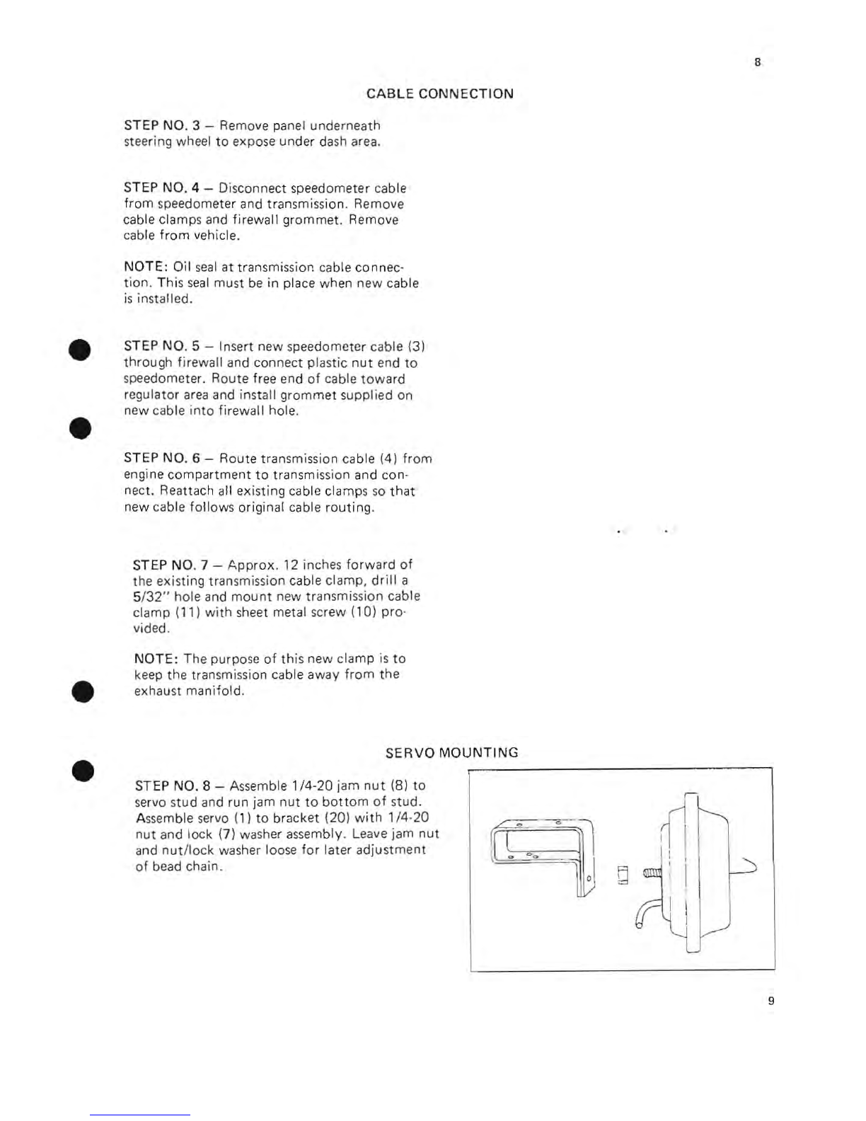
SERVO
MOUNTING
STEP NO. 8 - Assemble
1/4·20
jam
nut
(8)
to
servo s
tud
and run jam
nut
to
bottom
of
stud.
Assemble servo (1)
to
bracket (20)
with
1/4·
20
nut
and lock (7) washer assembly. Leave jam
nut
and
nut
/lock washer loose
for
later
adjustment
of
bead chain.
8
9