Edwards M528-09-160 User manual

M528-01-860
Issue A Original
Instruction Manual
CXS Inlet/Exhaust Temperature Indicator Accessory Kits
Description Item Number
Inlet Temperature Indicator Accessory Kit M528-09-160
Exhaust Temperature Indicator Accessory Kit M528-09-170

This page has been intentionally left blank.

© Edwards Limited 2013. All rights reserved. Page i
Edwards and the Edwards logo are trademarks of Edwards Limited.
Contents
M528-01-860 Issue A
Contents
Section Page
1 Introduction .......................................................................................1
1.1 Scope and definitions ................................................................................................... 1
1.2 Description of inlet temperature indicator .......................................................................... 1
1.3 Description of exhaust temperature indicator ...................................................................... 1
2 Installation .........................................................................................3
2.1 Installation safety ....................................................................................................... 3
2.2 Installing the inlet temperature indicator assembly ............................................................... 3
2.3 Installing the exhaust temperature indicator assembly ........................................................... 5
3 Operation and Maintenance .....................................................................7
For return of equipment, complete the HS Forms at the end of this manual.
Illustrations
Figure Page
1 Inlet Temperature Indicator Mounting Port Position ............................................................... 4
2 Inlet Temperature Indicator Mounting Position ..................................................................... 4
3 Exhaust Temperature Indicator Mounting Port Position ........................................................... 5
4 Exhaust Temperature Indicator Mounting Position ................................................................. 6
Associated Publications
CXS Pumping System Instruction Manual M528-00-880
WIKA operating instructions Models 53, 54, 55 (ATEX)
Trademark credits
Loctite®is a registered trademark of Henkel Corporation
cg/01/13

This page has been intentionally left blank.
M528-01-860 Issue A
Page ii © Edwards Limited 2013. All rights reserved.
Edwards and the Edwards logo are trademarks of Edwards Limited.
© Edwards Limited 2013. All rights reserved. Page 1
Edwards and the Edwards logo are trademarks of Edwards Limited.
Introduction
M528-01-860 Issue A
1Introduction
1.1 Scope and definitions
This manual provides installation instructions for the inlet/exhaust temperature indicator accessory kits.
Read this manual before you install the inlet/exhaust temperature indicators. Important safety information is
highlighted as WARNING and CAUTION instructions; you must obey these instructions. The use of WARNINGS and
CAUTIONS is defined below.
CAUTION
Cautions are given where failure to observe the instruction could result in damage to the equipment, associated
equipment and process.
1.2 Description of inlet temperature indicator
The inlet temperature indicator is fitted to the pump inlet spool above the inlet valve to provide local temperature
indication. The gauge has a scale range of -20°C to 200°C.
The WIKA temperature gauge model A5500 is supplied with the following ATEX classification.
II 2 GD c TX
The Inlet temperature indicator assembly is supplied fully assembled
1.3 Description of exhaust temperature indicator
The exhaust temperature indicator is fitted to the pump exhaust spool to provide local temperature indication.
The gauge has a scale range of -20°C to 200°C.
The WIKA temperature gauge model R5502 is supplied with the following ATEX classification.
II 2 GD c TX
The Exhaust pressure indicator assembly is supplied fully assembled
WARNING
Warnings are given where failure to observe the instruction could result in injury or death to
people.
Contents List
Description Quantity
Temperature Gauge -20°C to 200°C 1
Instruction Manual 1
Bimetal Thermometer Operating instructions 1
Contents List
Description Quantity
Temperature Gauge -20°C to 200°C 1
Instruction Manual 1
Bimetal Thermometer Operating instructions 1

M528-01-860 Issue A
Page 2 © Edwards Limited 2013. All rights reserved.
Edwards and the Edwards logo are trademarks of Edwards Limited.
This page has been intentionally left blank.
© Edwards Limited 2013. All rights reserved. Page 3
Edwards and the Edwards logo are trademarks of Edwards Limited.
Installation
M528-01-860 Issue A
2 Installation
2.1 Installation safety
2.2 Installing the inlet temperature indicator assembly
1. If the pump has previously been run on process start by performing the following steps:
Allow the pump system to cool to a safe temperature before you start maintenance work.
Isolate the inlet and exhaust pipe work from other processes. Vent and purge the pipe work before you start
any installation or maintenance work.
Vent and purge the dry pumping system before you start any installation or maintenance work.
Isolate the dry pumping system and other components in the process system from the electrical supply so
that they cannot be operated accidentally. Note that the emergency stop switch on the dry pumping system
is not an electrical isolator.
2. Remove the inlet temperature indicator assembly from the packaging, undo the compression nut and remove the
taper thread part of the compression fitting.
WARNING
Before installation is attempted refer to the CXS pumping system instruction manual to ensure
safety and compliance.
WARNING
Ensure that the pump's electrical supply is fully isolated before undertaking the installation.
WARNING
The surfaces of the inlet and exhaust can be very hot when the CXS system is running. Allow these
surfaces to cool to a safe temperature before installing the inlet/exhaust pressure indicator.
WARNING
Leak test the system after installation and seal any leaks found to prevent leakage of dangerous
substances out and leakage of air into the system.
WARNING
Personal protective equipment should be checked and used as specified by its supplier. Hazardous
chemicals that have been pumped are located within the pumps and piping. Use of suitable
protective gloves and clothing along with a respirator is recommended if contact with substances
is anticipated. Particular caution should be exercised when working with fluorinated materials
which may have been exposed to temperatures greater than 260°C. Refer to Edwards Material
Safety Data Sheets for detailed information.
M528-01-860 Issue A
Page 4 © Edwards Limited 2013. All rights reserved.
Edwards and the Edwards logo are trademarks of Edwards Limited.
Installation
Note: The compression fitting has been pre-swaged onto the temperature gauge stem to ensure correct
positioning in the inlet spool.
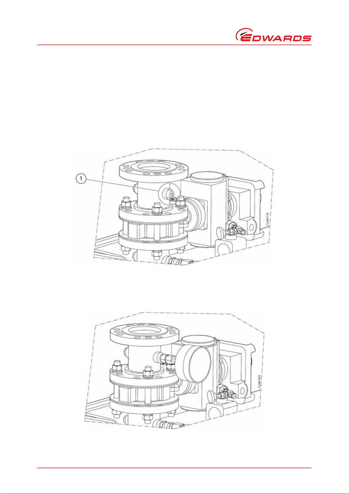
3. Remove the appropriate 1/2” BSP plug from the inlet spool located above the inlet isolation valve as shown in
Figure 1.
4. Apply a suitable thread sealant such as Loctite®577 to the taper thread of the compression fitting and screw
into the 1/2” BSP connection. Insert the temperature gauge stem into the compression fitting and retighten the
compression fitting nut ensuring correct orientation as shown in Figure 2.
5. Leak test the inlet temperature indicator assembly and seal any leaks found.
Figure 1 - Inlet Temperature Indicator Mounting Port Position
Figure 2 - Inlet Temperature Indicator Mounting Position
1. Remove 1/2” BSP blanking plug

© Edwards Limited 2013. All rights reserved. Page 5
Edwards and the Edwards logo are trademarks of Edwards Limited.
Installation
M528-01-860 Issue A
2.3 Installing the exhaust temperature indicator assembly
1. If the pump has previously been run on process start by performing the following steps:
Allow the pump system to cool to a safe temperature before you start maintenance work.
Isolate the inlet and exhaust pipe work from other processes. Vent and purge the pipe work before you start
any installation or maintenance work.
Vent and purge the dry pumping system before you start any installation or maintenance work.
Isolate the dry pumping system and other components in the process system from the electrical supply so
that they cannot be operated accidentally. Note that the emergency stop switch on the dry pumping system
is not an electrical isolator.
2. Remove the exhaust temperature indicator assembly from the packaging, undo the compression nut and remove
the taper thread part of the compression fitting.
Note: The compression fitting has been pre-swaged onto the temperature gauge stem to ensure correct
positioning in the exhaust spool.
3. Remove the appropriate 1/2” BSP plug from the exhaust spool as shown in Figure 3.
4. Apply a suitable thread sealant such as Loctite®577 to the taper thread of the compression fitting and screw
into the 1/2” BSP connection. Insert the temperature gauge stem into the compression fitting and retighten the
compression fitting nut ensuring correct orientation as shown in Figure 4.
5. Leak test the exhaust temperature indicator assembly and seal any leaks found.
Figure 3 - Exhaust Temperature Indicator Mounting Port Position
1. Remove 1/2” BSP blanking plug

M528-01-860 Issue A
Page 6 © Edwards Limited 2013. All rights reserved.
Edwards and the Edwards logo are trademarks of Edwards Limited.
Installation
Figure 4 - Exhaust Temperature Indicator Mounting Position

© Edwards Limited 2013. All rights reserved. Page 7
Edwards and the Edwards logo are trademarks of Edwards Limited.
Operation and Maintenance
M528-01-860 Issue A
3 Operation and Maintenance
Please refer to the CXS pumping system and temperature gauge instruction manualsfor operating instructions. There
is no requirement for routine maintenance of the inlet/exhaust temperature indicator assemblies.

M528-01-860 Issue A
Page 8 © Edwards Limited 2013. All rights reserved.
Edwards and the Edwards logo are trademarks of Edwards Limited.
This page has been intentionally left blank.

This page has been intentionally left blank.

This page has been intentionally left blank.

Return the equipment or components for service
Before you send your equipment to us for service or for any other reason, you must send us a
completed Declaration of Contamination of Vacuum Equipment and Components – Form HS2. The
HS2 form tells us if any substances found in the equipment are hazardous, which is important for
the safety of our employees and all other people involved in the service of your equipment. The
hazard information also lets us select the correct procedures to service your equipment.
We provide instructions for completing the form in the Declaration of Contamination of Vacuum
equipment and Components – Procedure HS1.
If you are returning a vacuum pump, note the following:
If a pump is configured to suit the application, make a record of the configuration before
returning the pump. All replacement pumps will be supplied with default factory settings.
Do not return a pump with accessories fitted. Remove all accessories and retain them for
future use.
The instruction in the returns procedure to drain all fluids does not apply to the lubricant in
pump oil reservoirs.
Download the latest documents from www.edwardsvacuum.com/HSForms/, follow the procedure in
HS1, fill in the electronic HS2 form, print it, sign it, and return the signed copy to Edwards.
Note: If we do not receive a completed HS2 form, we will not accept the return of the
equipment.
P80081000, Issue A

P800‐80‐000IssueT
edwardsvacuum.com
This manual suits for next models
1
Table of contents
Other Edwards Measuring Instrument manuals

Edwards
Edwards AIM-S-NW25 User manual

Edwards
Edwards PRG20K User manual

Edwards
Edwards IG40 BA User manual

Edwards
Edwards AIM-S-NW25 User manual

Edwards
Edwards Barocel 7045 User manual

Edwards
Edwards TruWave User manual

Edwards
Edwards AIM-S-NW25 User manual

Edwards
Edwards APG100 User manual

Edwards
Edwards AIM-S-NW25 User manual

Edwards
Edwards FSRZI-A Assembly instructions


