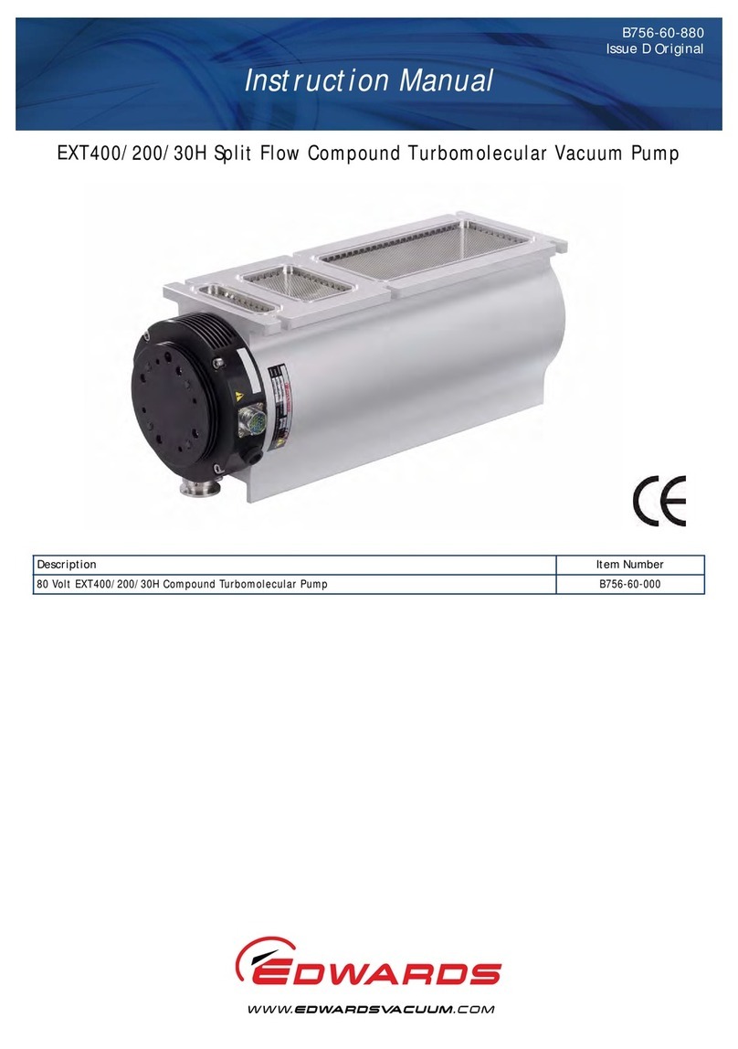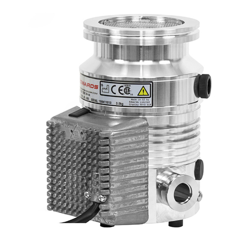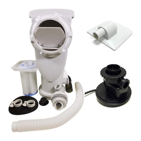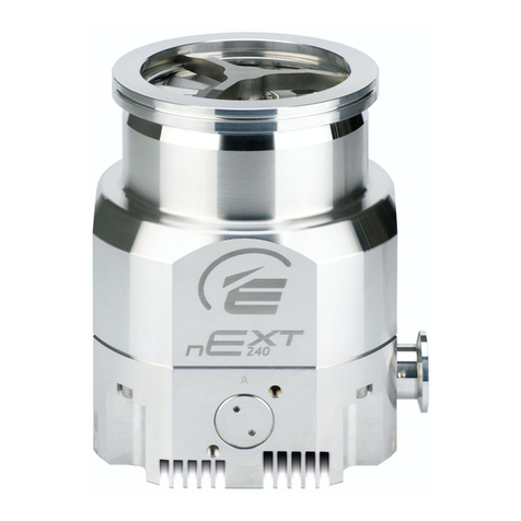
The nEXT pump is supplied with an inlet screen. The inlet screen is installed in the
centering O‑ring. The nEXT pumps with NW25 interstage port is supplied with an inlet
strainer. The inlet strainer is installed in the interstage port. The inlet screen and inlet
strainer prevent the damage to the pump caused by debris entering the pump.
The nEXT pump has a vent port for venng the pump and vacuum system to the
atmospheric pressure. The pump has a manual vent valve which can be replaced with a
TAV5 or TAV6 solenoid‑operated vent valve (available as an accessory, refer to
Accessories on page 92). The on‑board motor controller can control the TAV valve.
The nEXT pump has a purge port through which an inert purge gas can be introduced to
protect the bearing and motor from corrosion. You can install an oponal vent port
adapter and purge restrictor to the purge port to control the ow rate of the purge gas
and to lter the gas supply. Refer to Accessories on page 92.
Air coolers and a water cooling block are available as an oponal accessories to cool the
nEXT pumps. Refer to Accessories on page 92.
2.2 Pump controller
The pump controller has the drive electronics that control the pump operaon and the
TAV vent valve. The connector socket is given at the side of the controller where the
TAV vent valve can be plugged in. Refer to Controller connector socket on page 29.
The controller has three indicator LED's which signal the general status, operaon and
the service status of the pump. The LEDs can be used for fault nding if a problem
occurs. Refer to Indicator LED's on page 30.
The drive electronics system has a number of built‑in safety features to prevent
the pump from damage during sustained high pressure or temperature.
▪ The electronics constantly monitors the temperature in the controller and the
temperature of the motor in the pump. If the controller or the motor gets too hot,
the controller decreases the power supplied to the pump motor and the pump
speed decreases. If the rotaonal speed of the pump decreases below 50% of the
full speed, the electronics can trip into a fail condion, depending on the system
conguraon. Refer to Timer on page 12.
▪ If the inlet pressure of the pump increases, the power supplied to the pump motor
increases to counteract the gas friconal load. When the built‑in maximum power
limit is reached, the speed of the pump starts to decrease. If the rotaonal speed
of the pump decreases below 50% of the full speed, the electronics can trip into
fail condion, depending on how the system has been congured. Refer to Timer
on page 12.
▪ If the electrical supply fails, the controller uses the motor in the pump as a
generator. This means the pump has its own regenerave supply and a separate
baery for an emergency power backup is not necessary. The regenerated energy
maintains the electrical supply to the controller, the vent valve or the fan aached
to the controller connector unl the pump speed decreases below 50% of the full
rotaonal speed to make sure that the vent valve stay shut unl below 50% of the
full rotaonal speed and prevent the pump from venng at a full speed. It makes
sure that the serial link and signals on the parallel interface stays acve unl the
pump speed decreases below 50%.
Page 11
B85200880_D - Introducon


