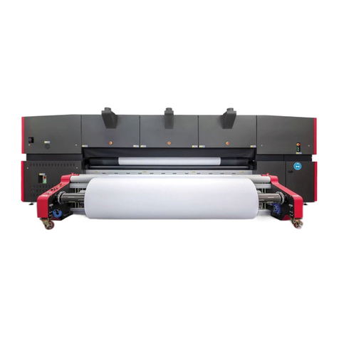
EFI Pro 16h User manual


Copyright © 2017Electronics for Imaging, Inc. All rights reserved.
All trademarks, registered trademarks, and product names used in this document are the property of their respective owners.
The information contained in this document is confidential and proprietary to Electronics for Imaging, Inc (EFI). This information is provided
only to authorized representatives of EFI and EFI customers solely for the purpose of facilitating the use of EFI’s products. No information
contained herein may be disclosed to any unauthorized person for any purpose whatsoever without the prior written consent of EFI.
EFI makes no representations or warranties with respect to the contents of this document. Further, EFI reserves the right to revise or
change this publication and the products it describes without notice.
English is the original language of this document.
This product may be covered by one or more of the following U.S. Patents
5,109,241, 5,150,454, 5,170,182, 5,212,546, 5,260,878, 5,276,490, 5,278,599, 5,335,040, 5,343,311, 5,398,107, 5,424,754,
5,442,429, 5,459,560, 5,467,446, 5,506,946, 5,517,334, 5,537,516, 5,543,940, 5,553,200, 5,563,689, 5,565,960, 5,583,623,
5,596,416, 5,615,314, 5,619,624, 5,625,712, 5,640,228, 5,666,436, 5,682,421, 5,729,665, 5,745,657, 5,760,913, 5,799,232,
5,818,645, 5,835,788, 5,859,711, 5,867,179, 5,937,153, 5,940,186, 5,959,867, 5,970,174, 5,982,937, 5,995,724, 6,002,795,
6,025,922, 6,035,103, 6,041,200, 6,065,041, 6,081,281, 6,112,665, 6,116,707, 6,122,407, 6,134,018, 6,141,120, 6,166,821,
6,173,286, 6,185,335, 6,201,614, 6,209,010, 6,215,562, 6,219,155, 6,219,659, 6,222,641, 6,224,048, 6,225,974, 6,226,419,
6,238,105, 6,239,895, 6,256,108, 6,269,190, 6,271,937, 6,278,901, 6,279,009, 6,289,122, 6,292,270, 6,299,063, 6,310,697,
6,321,133, 6,327,047, 6,327,050, 6,327,052, 6,330,071, 6,330,363, 6,331,899, 6,337,746, 6,340,975, 6,341,017, 6,341,018,
6,341,307, 6,347,256, 6,348,978, 6,356,359, 6,366,918, 6,369,895, 6,381,036, 6,400,443, 6,429,949, 6,449,393, 6,457,823,
6,476,927, 6,487,568, 6,490,696, 6,501,565, 6,519,053, 6,539,323, 6,543,871, 6,546,364, 6,549,294, 6,549,300, 6,550,991,
6,552,815, 6,559,958, 6,572,293, 6,590,676, 6,599,325, 6,606,165, 6,616,355, 6,618,157, 6,633,396, 6,636,326, 6,637,958,
6,643,317, 6,647,149, 6,657,741, 6,660,103, 6,662,199, 6,678,068, 6,679,640, 6,687,016, 6,707,563, 6,741,262, 6,748,471,
6,753,845, 6,757,436, 6,757,440, 6,778,700, 6,781,596, 6,786,578, 6,816,276, 6,825,943, 6,832,865, 6,836,342, 6,850,335,
6,856,428, 6,857,803, 6,859,832, 6,866,434, 6,874,860, 6,879,409, 6,885,477, 6,888,644, 6,905,189, 6,930,795, 6,950,110,
6,956,966, 6,962,449, 6,967,728, 6,974,269, 6,977,752, 6,978,299, 6,992,792, 7,002,700, 7,023,570, 7,027,187, 7,027,655,
7,031,015, 7,046,391, 7,054,015, 7,058,231, 7,064,153, 7,073,901, 7,081,969, 7,090,327, 7,093,046, 7,095,518, 7,095,528,
7,097,369, 7,099,027, 7,105,585, 7,116,444, 7,177,045, 7,177,049, 7,177,472, 7,204,484, 7,206,082, 7,212,312, 7,229,225,
7,233,397, 7,233,409, 7,239,403, 7,245,400, 7,248,752, 7,259,768, 7,259,893, 7,280,090, 7,296,157, 7,301,665, 7,301,667,
7,301,671, 7,302,095, 7,302,103, 7,304,753, 7,307,761, 7,342,686, 7,343,438, 7,349,124, 7,365,105, 7,367,060, 7,367,559,
7,389,452, 7,396,119, 7,396,864, 7,397,583, 7,397,961, 7,426,033, 7,431,436, 7,433,078, 7,453,596, 7,460,265, 7,460,721,
7,461,377, 7,463,374, 7,466,441, RE36,947, RE38,732, D341,131, D406,117, D416,550, D417,864, D419,185, D426,206,
D426,206, D439,851, D444,793.

EFI Inkjet Solutions
United States
1 Vutek Place
Meredith, New Hampshire 03253 USA
http://w3.efi.com/Vutek/Products
http://w3.efi.com/WideFormat/Products
This document is published on-line at http://inkjet.support.efi.com.
Document ID: OMM-00131 Rev. E
Americas EU, Middle East, Africa APAC
Customer Care Customer Care Customer Care
United States: 855-EFI-4HLP (855-334-4457) +31 20 658 8070 +1 650 357 4790
412-690-4321
Canada/Mexico/South America: +1 650 357 4790
Technical Support Technical Support Technical Support
North America: 855-EFI-4HLP (855-334-4457) +32 2 749 94 50 +65 6221 2765
Mexico and South America: +1 412-690-4321 DE +49 2102 745-4500
NL +31 20 658-8080/8069
UK +44 12462-98085
Email: [email protected]
Online Request Support Online Request Support Online Request Support
https://inkjet.support.efi.com https://inkjet.support.efi.com https://inkjet.support.efi.com

Revision History
• Added note to end of section 3.8 to “Check all electrical connectors, Luer fittings and TB screws
in the electrical cabinet.”
• Added anti-coning to end of section 3.10.3
• Updated text and links in section 1.3 Customer Resources
A 05/12/2017 Released DR 3696
B 06/21/2017 Added step to section 4.15 to “Have the customer go to https://inkjet.support.efi.com to
request an account for his printer.”
DR 4345
C 07/18/2017 DR 4338
DR 4413
D 08/07/2017 DR 4501
E10/26/2017 Removed or notated removal of dancer on take-up side of printer DR 4569

Document ID: OMM-00131 Rev. E v
Table of Contents
1.0 Introduction ............................................................................................................................................................ 7
1.1 About This Guide ............................................................................................................................................................................... 7
1.2 Objectives ........................................................................................................................................................................................... 7
1.3 Customer Resources ......................................................................................................................................................................... 7
1.4 Guide Conventions ........................................................................................................................................................................... 8
1.5 Note, Warning, Caution, Danger .................................................................................................................................................... 8
1.6 Storing Ink .......................................................................................................................................................................................... 8
2.0 UV Safety Acknowledgment Form .................................................................................................................... 10
3.0 Pro 16h Printer Installation Procedures .......................................................................................................... 12
3.1 Unpacking Personnel ..................................................................................................................................................................... 12
3.2 Unpacking Tools ............................................................................................................................................................................. 12
3.3 Moving the Printer .......................................................................................................................................................................... 12
3.4 Unpacking Printer ........................................................................................................................................................................... 13
3.5 Positioning Printer ..........................................................................................................................................................................15
3.5.1 Lifting the Printer from Pallet ........................................................................................................................................15
3.5.2 Install Printer Feet ............................................................................................................................................................ 16
3.6 Leveling the Printer ........................................................................................................................................................................ 18
3.6.1 Level Locations ................................................................................................................................................................. 18
3.6.2 Adjusting the Leveling Feet ............................................................................................................................................ 19
3.7 Operator Station Installation ........................................................................................................................................................20
3.7.1 Monitor Cable Routing.....................................................................................................................................................22
3.7.2 Monitor and Keyboard Tray Installation ......................................................................................................................23
3.7.3 Keyboard and Mouse Connections ...............................................................................................................................25
3.8 Computer Installation and Connections ....................................................................................................................................26
3.8.1 Computer Connections ...................................................................................................................................................26
3.8.2 USB Board Connection ....................................................................................................................................................27
3.8.3 Computer Installation .....................................................................................................................................................27
3.9 Installation of Rolled Media Handling System (Take-Up and Feed Roll Assemblies) .........................................................28
3.9.1 Take-Up Roll Assembly Installation ..............................................................................................................................28
3.9.2 Feed Roll Assembly Installation .....................................................................................................................................30
3.10 Roll-to-Roll Alignment Procedure .............................................................................................................................................32
3.10.1 Alignment Process.......................................................................................................................................................... 33
3.10.2 Leveling the Take-Up Roll Assembly ..........................................................................................................................36
3.10.3 Install Anti-Coning.........................................................................................................................................................38
3.11 Carriage Preparation ....................................................................................................................................................................41
3.11.1 Removal of Carriage Shipping Brackets .....................................................................................................................41
3.12 Media Belt Alignment and Tensioning ......................................................................................................................................42
3.12.1 Measurement and Alignment Checks.........................................................................................................................42

Document ID: OMM-00131 Rev. E vi
3.12.2 Tension Fixture ...............................................................................................................................................................43
3.12.3 Media Belt Tension Adjustments .................................................................................................................................44
3.13 Install Media Vacuum Foot Pedal ...............................................................................................................................................45
3.14 Assembly and Installation of Rigid Media Tables ...................................................................................................................46
3.14.1 Media Table Base Assembly..........................................................................................................................................47
3.14.2 Media Table Top Assembly...........................................................................................................................................48
3.15 Installing Ink ..................................................................................................................................................................................49
3.16 Printer Electrical Power ...............................................................................................................................................................50
3.16.1 Main Power Cable Wiring..............................................................................................................................................50
3.16.2 Main Breaker Panel.........................................................................................................................................................51
3.16.3 Main Power Isolation Switch........................................................................................................................................51
3.16.4 Green Printer ON Button (At Operator Station)........................................................................................................52
3.17 Performing Power On Checks .....................................................................................................................................................52
3.18 Printing Acceptance Prints ..........................................................................................................................................................52
3.19 Rigid Media Fence Alignment .....................................................................................................................................................53
3.19.1 Rigid Media Fence Alignment Check ..........................................................................................................................53
3.19.2 Rigid Media Fence Alignment Adjustments...............................................................................................................54
3.20 Setting Print Margins ...................................................................................................................................................................56
3.20.1 Print Head “ZERO” Position ..........................................................................................................................................56
3.20.2 GUI Settings.....................................................................................................................................................................58
4.0 Pro 16h Printer Installation Checklist .............................................................................................................. 59
4.1 Installation Requirements .............................................................................................................................................................59
4.2 Site Preparation ...............................................................................................................................................................................59
4.3 Delivery .............................................................................................................................................................................................59
4.4 Unpacking Printer ...........................................................................................................................................................................60
4.5 Position. ............................................................................................................................................................................................60
4.6 Initial Printer Leveling ...................................................................................................................................................................60
4.7 Preparing Carriage ..........................................................................................................................................................................60
4.8 Installing and Aligning Rolled Media Handling Systems .........................................................................................................60
4.9 Power Off Checks ............................................................................................................................................................................ 61
4.10 Connecting Electrical Supplies .................................................................................................................................................. 61
4.11 Mechanical Alignments. .............................................................................................................................................................. 61
4.12 Power On Checks .......................................................................................................................................................................... 61
4.13 Printer Critical Alignments .......................................................................................................................................................... 61
4.14 Install Ink ........................................................................................................................................................................................ 61
4.15 Acceptance Phase .........................................................................................................................................................................62
4.16 Operator Training Phase .............................................................................................................................................................62
4.17 Service Engineer Sign-Off ............................................................................................................................................................62

Document ID: OMM-00131 Rev. E 7
1.0 Introduction
This Field Service Installation Guide describes the EFI Pro 16h Wide Format Printer installation procedure. It contains site
preparation requirements, unpacking procedures, and setup requirements.
1.1 About This Guide
This guide assists trained Field Service Engineers (FSEs) in installing the Pro 16h Wide Format Printer.
The printer requires a methodical installation, therefore, this guide focuses on fundamental skills and concepts vital to successful printer
installation. It does not cover advanced operation concepts, file ripping or printer operational modes.
1.2 Objectives
This guide has several objectives:
• Preparing site - FSEs are instructed on the best practices each site must adhere to when supporting an installation.
• Unpacking printer - Procedures are included to assist FSEs in properly uncrating and unpacking a printer.
• Teaching safe printer operation - Users are taught basic safety principles to protect themselves from injury and to protect
printers from damage due to improper use.
• Printing an ACTARG File - Users learn basic printing practices, including loading media, importing files, and setting print options.
• Performing daily maintenance - Users learn basic maintenance tasks, including ink loading and care, jet pack cleaning and
maintenance, and general printer maintenance and care.
• Learning printer control software - Users are taught printer software fundamentals and how to complete actions using the soft-
ware, or Graphical User Interface (GUI).
1.3 Customer Resources
EFI Inkjet Solutions provides additional resources to help personnel operate and maintain printer properly.
• Customer Support Web Site - http://inkjet.support.efi.com/index.php - Contains Operations and Maintenance Guides, techni-
cal supplements, advisory bulletins, and resources such as software updates and drivers.
• Printer Safety Guide - http://inkjet.support.efi.com/doc.php?doc=683 - The Printer Safety Guide contains information critical
to safe printer operation for all customers.
• Training - http://inkjet.support.efi.com/training/index.php - Operator training is an essential part of printer installation and
operation. EFI Inkjet Solutions provides an educational support system assisting new and experienced operators to develop and
maintain skills.

Document ID: OMM-00131 Rev. E 8
1.4 Guide Conventions
This guide uses these conventions:
1.5 Note, Warning, Caution, Danger
The following messages convey specific notes or warnings to printer operators.
Note: To emphasize points or remind operators of important concepts, or to indicate minor problems in the outcome of
certain actions.
Important! To inform readers about an important step in the procedure that must NOT be missed.
Caution! To warn operators about possible damage to equipment, loss of data or about potential problems in the outcome
of what they are doing.
Warning: To warn operators about the possibility of injury to themselves or others, or serious damage to equipment.
Danger! To warn operators about the possibility of serious or fatal injury to themselves or others.
1.6 Storing Ink
UV-curable ink has a shelf life of 12 months.
Rotate ink using the oldest stock first to avoid ink loss due to expiration. The expiration date is on the outside of each container.
Dispose of expired ink in a manner consistent with local regulations.
Convention Meaning
1. Step Numbered style begins a procedure.
An arrow and number indicating a printer component or location, with accompanying list of
components. For example:
1 Red status button
Figure 1-1: Status Button A unique figure number at the bottom of all images, with description.
Note: Red text defines important information or reminders; see Note, Warning, Caution, Danger
Hyperlink Blue underlined text indicates a link to a subject within the guide or on the Internet.
1

Document ID: OMM-00131 Rev. E 10
2.0 UV Safety Acknowledgment Form
I, _____________________________________, hereby acknowledge that the UltraViolet (UV) light and UV-curable ink used in EFI UV
printers may negatively effects human health. The following safety and health concerns have been individually and explicitly explained to
me.
Safety Concern Initials
1. Impermeable protective wear must be worn while handling UV-curable ink, including nitrile gloves,
a protective apron, shoes, and safety glasses.
2. UV light exposure can cause permanent eye damage.
3. Never look at or in the direction of the UV curing lamp while it is on.
4. If UV-curable ink contacts the eyes, immediately remove contact lenses and begin flushing the eyes
with large amounts of cool water for at least 15 minutes; immediately contact a physician. Material
Safety Data Sheets (MSDS) describing the ink should be taken to the doctor.
5. Exposure to UV-curable ink in or around the eyes can cause permanent eye damage.
6. Dermal exposure to UV-curable ink may cause skin irritation, dermatitis, and/or an allergic reaction
(sensitization).
7. The allergic reaction to UV-curable ink may worsen over time.
8. Upon contact of skin with UV-curable ink, immediately flush the area with large amounts of cool
water, wash with mild soap, and contact a physician if irritation persists. Never use solvent to
remove UV ink from the skin.
9. The UV curing process generates a by-product, ozone, that is a respiratory irritant. All UV printers
shall be properly vented to limit exposure; use process enclosures, local exhaust ventilation, and/or
other engineering controls to control exposure.
10. Ingestion of ink is irritating to mouth, throat, and stomach; can cause abdominal discomfort,
nausea, vomiting and diarrhea. Anyone who ingests UV-curable ink must consult with a physician
immediately.
11. I understand although all safety precautions have been taken, adverse reactions to UV ink and UV
light may still occur in some people, which may include me.
Page 1 of 2

Document ID: OMM-00131 Rev. E 11
I understand that the aforementioned precautions may not be exhaustive and may not prevent any injury. I was advised to consult with a
physician immediately in case of over-exposure to the UV light and UV-curable ink. By signing below, I hereby acknowledge the above pre-
scribed safety measures. I will hold EFI Inkjet Solutions harmless and accept all responsibility for medical or health conditions incurred
resulting from my failure to adhere to the prescribed safety measures. I further agree that I will notify all operators, personnel, and any
persons near or around the printer of the potential dangers of exposure to UV light and UV ink and that I will cause all operators, personnel,
and any persons in the vicinity of the printer to read and sign this UV Safety Acknowledgement Form.
12. I understand that I should never disable or modify the UV safety features of my printer or handle
UV-curable inks. I acknowledge that by disabling or modifying the UV Safety features of my printer,
I may expose myself and others to unsafe levels of UV light and radiation and that by doing so, I am
making these modifications at my own risk and will hold EFI harmless in case of any negative effects
resulting therefrom.
13. I have read and understand the applicable Printer Safety Guide, available by calling Technical
Support, the Distributor, or visiting http://inkjetsupport.efi.com.
14. I acknowledge that I have read and understand the applicable MSDS for each of the inks, solvents,
and chemicals used in or in connection with the printer.
Signature Date
Trainer, FSE, or Manager Material Version
Printer Model Serial Number
Page 2 of 2
Safety Concern Initials

Document ID: OMM-00131 Rev. E 12
3.0 Pro 16h Printer Installation Procedures
This chapter contains the Pro 16h Wide Format Printer Installation procedures. If replacement parts are required during
installation, please specify that the part order is for an installation. If the replacement part number is not known, please inform
Product Support that the part being ordered is for an installation. The part will be ordered for next day shipment and charged to
the installation process and not warranty. This process allows the Accounting Department to correctly track warranty costs for
each printer.
3.1 Unpacking Personnel
At least two persons are needed to safely unpack and move the printer.
3.2 Unpacking Tools
The following tools are required for unpacking the printer:
∙FlatTipScrewdriver
∙TwoAdjustableWrenches
∙ASharpUtilityKnife
∙StandardToolKit
3.3 Moving the Printer
Follow these safety precautions when moving the printer.
Caution! If lifting end of pallet with a forklift, do not allow pallet to slide off fork ends and drop to the
ground. See the Pro 16h Specifications Document for dimensions and weights to assure
the fork lift truck has the capacity to lift the printer.
Caution! Never lift Printer from the ends when it is not on its pallet. This can cause serious damage to
the frame, compartments, side access doors and mounting brackets.
Caution! The printer and printer components are heavy and could cause serious injury if improper
lifting techniques are used. Use proper lifting techniques when installing Pro 16h Printers.

Document ID: OMM-00131 Rev. E 13
3.4 Unpacking Printer
Follow these instructions to unpack printer.
1. Remove the printer pallet/crate from the truck. The crate/pallet can be dragged approximately 6” off the floor with a fork lift truck
by inserting forks under pallet end and dragging the crate/pallet off the truck.
Important! Use safety chains secured to the drag eyelet to ensure the printer does not slip off forks when dragging.
2. Inspect crate for any external damage. If any external damage is noted, notify the Facilities Manager and shipping company, and
take photos of the damage prior to opening the crate.
3. Place crate as close to the final installation location as possible.
4. Disassemble the crate as follows:
A.Remove the Top Panel Bolts. (Two people are required to lift and remove the top panel). Pry top panel up with a screwdriver to remove).
B.Unbolt the end panels and support the side panels as the ends are removed.
C.Support the side panels until they are removed.
D.Remove Crate Panels to Expose Printer and Tables.
Note: The side panels rest on the metal tabs welded to the pallet.
Figure 3-1: Crate Disassembly
1 End Panels 3 Top Panel
2 Side Panels 4 Pallet Within
1
2
3
4

Document ID: OMM-00131 Rev. E 14
5. Inspect plastic wrapping on printer for any external damage. If any external damage exists, notify the Facilities Manager and ship-
ping company, and take photos of any damage before removing plastic wrapping.
6. Remove the plastic covering from the printer.
Peripherals
Peripherals
Figure 3-2: Packaged Printer Peripherals (H1625 Carriage Shown)
7. inspect unwrapped printer for damage. If any damage is found, notify the Facilities Manager and shipping company. Take photos of
the damage before continuing
8. Verify ShockWatch® or equivalent tip/impact indicators have notbeen tripped. If are any indicators are tripped, notify the Facilities
Manager, the shipping company, and your manager or director immediately, and take photos of the indicator before continuing.
9. Remove all peripherals (boxes, parts, and accessories) that are to be attached to the printer. This includes the computer monitor
and keyboard tray Rolled Media Handling Systems (Front and Rear, alignment fixture, and other parts.
10. Unpack remaining crates that accompanied printer.
11. Check spares kit and inventory parts as time permits.

Document ID: OMM-00131 Rev. E 15
3.5 Positioning Printer
Follow these instructions to position printer correctly.
Important! Reference the Printer Specifications, ITS-00143, Pro 16h Printer Specifications for printer space requirements
and placement information.
3.5.1 Lifting the Printer from Pallet
Lift the printer from the pallet as described in this paragraph.
Danger! Ensure that the forklift or pallet jack is properly rated for the printer’s weight. It is extremely important to lift
the printer slowly to ensure it does not tip left or right or front to back. Do not attempt to fully lift the printer
until it is certain that the forks are located at the printer’s center of gravity (CG).
1. Ensure the wheels are installed and properly secured on the
printer.
2. Using a fork lift or pallet jack, center the forks under the printer
and move the forks all the way under the printer
3. Ensure that the lifting forks are at the printer’s center of gravity
(CG).
4. Lift the printer off the pallet ans move it back so that the under-
side of the printer is off the pallet and exposed.
5. Ensure that the printer is stable on the forks as it is necessary
to work under the printer to install the printer feet.
Figure 3-3: Center of Gravity Lift location
1PrinterCG
2Forks
1
2

Document ID: OMM-00131 Rev. E 16
3.5.2 Install Printer Feet
Install the printer feet as follows:
1. The Printer Feet are threaded and include an adjustment nut and
a lock nut. as shown.
2. While the printer is on the fork lift or pallet jack, install the feet
by screwing the threaded shaft into the installation location next
to the printer wheels.
There are four installation locations, one adjacent to each
printer wheel.
Figure 3-4: Printer Foot Detail
1AdjustmentNut
2LockNut
1
2
Figure 3-5: Printer Installation Location
1 Printer Wheels 2 Printer Foot
3 Foot Installation Location
1
2
3

Document ID: OMM-00131 Rev. E 17
1. Thread the shafts into the installation location only far
enough to ensure that the wheels will not touch the floor
when the printer is lowered.
2. Check the installation before lowering the printer by mea-
suring the distance from the bottom of the printer to the
bottom of the rubber pads on the bottom of the feet to
ensure it is more than the wheel hight. (Approximately 4
Inches)
3. Ensure that all four feet are installed with the same
height measurement.
4. When all four feet are installed at the proper height, the
printer can be moved to its final location and lowered
onto the floor. (Ensure that only the feet make contact
with floor - the wheels must NOT touch the floor)
5. The printer can now be properly leveled.
4 Inches
Figure 3-6: Printer Foot Measurement
Ensure Foot Extends Below Wheel
Figure 3-7: Printer Foot Installed

Document ID: OMM-00131 Rev. E 18
3.6 Leveling the Printer
Using Machinist’s Levels or equivalent, follow these instructions to level the printer.
3.6.1 Level Locations
Place three levels at the locations shown prior to making adjustments to the leveling feet.
1. Place two levels on the left and right sides of the media belt to check front-to-back level and to check for printer “twist”.
2. Place another level on the center of the media belt for side-to-side leveling.
Left Side Level Center Level Right Side Level
Figure 3-8: Level Locations

Document ID: OMM-00131 Rev. E 19
3.6.2 Adjusting the Leveling Feet
Level the printer front-to-back and side-to-side as described in this paragraph. It is important to make all adjustments with the
levels in place. Make adjustments for leveling front-to-back and side-to-side at the same time.
1. Use an adjustable wrench, rotate the foot so that it moves
up or down.
2. Check the levels to ensure the printer is leveling out as
each foot is adjusted.
3. Ensure printer is level in all directions.
4. Carefully observe the left and right levels to avoid printer
“twist”.
5. When satisfied that he printer is level in all directions,
tighten the lock nuts so the feet are securely fastened and
will not loosen.
4 Inches
Figure 3-9: Printer Foot Measurement
Secure Locknut
Adjust Height
with Wrench
Figure 3-10: Leveling Feet Adjustments

Document ID: OMM-00131 Rev. E 20
3.7 Operator Station Installation
The Operator Station is comprised of the monitor, keyboard tray, keyboard and mouse. Install and connect Operator Station
components as described in the following paragraphs and illustrations.
A brief overview of operator station installation is provided below:
1. Route the cables for the monitor and keyboard tray connections.
2. Install the Monitor to the Monitor mounting bracket and make cable connections.
3. Remove the Interlock Override Keys and place in Keyhole for later use.
4. Install the Keyboard Tray and make cable connections.
5. Place the keyboard and mouse onto the keyboard tray and connect.
1
2
3
4
5
6
Figure 3-11: Monitor and Keyboard Installation
1 Monitor Mounting Bracket 2 Remove Interlock Override Keys and place in Keyhole 3 LCD Monitor Assembly
4 Place Keyboard and Mouse Here 5 Keyboard Tray Assembly 6 Keyboard Mounting Screw
Table of contents
Other EFI Printer manuals

