EG&G ORTEC 463 Service manual

A
r\i
EGkG
c
o
rs/i
F=>/\
f\i
^
Model
463
Constant
Fraction
Discriminator
Vice
Manual
jfi*
I'-'I*
iiiypiiiiimiiiiyliiiPiilliiiiiiiiiiiiiiiiiilii
iiiiiiiiiiiiiiBii;yiiiiiyii)iiiiiiiifflillfllllllliliiy
.;-,■■
■.:■
-y-t
■■■:■-'%;■:■
:
■'.fii.
.
M
■Mlki
Model
463
Constant
Fraction
Discriminator
Operating
and
Service
Manual
Printed
in
U.S.A.
©
ORTEC
Incorporated
1971
1127
03C
0771
01

TABLE
OF
CONTENTS
Page
WARRANTY
^
PHOTOGRAPH
1.
GENERAL
^
2.
SPECIFICATIONS
1
3.
INSTALLATION
2
3.1
General
2
3.2
Connection
to
Power
2
3.3
Input
Connection
2
3.4
Output
Connections
2
4.
OPERATION
3
5.
CIRCUIT
DESCRIPTION
3
6.
MAINTENANCE
4
6.1
General
4
6.2
Level
Discriminator
Zero
Adjustment
4
6.3
Negative
Output
Pulse
Shape
and
Amplitude
Adjustment
4
6.4
Walk
Adjustment
5
7.
APPLICATIONS
7
7.1
Timing
with
Fast
Scintillators
7
7.2
Timing
with
Large
Ge(Li)
Detectors
7
7.3
Timing
with
Surface
Barrier
Detectors
9
7.4
Timing
with
High-Resolution
Low-Energy
Photon
Spectrometers
10
7.5
Timing
with
Nal(TI)
Scintillators
11
BIBLIOGRAPHY
12
SCHEMATIC
463-0101-S1
ORTEC
463
Schematic
IV
LIST
OF
FIGURES
Page
4
Fig.
5.1.
Ideal
Pulse
Shapes
Illustrating
the
Constant
Fraction
Discriminator
Operation
Fig.
5.2.
Signal
Shapes
Illustrating
Detection
of
the
Zero-Crossing
Point
of
Constant
Fraction
Signal
Fig.
6.1.
Block
Diagram
of
System
for
Walk
Test
of
the
ORTEC
463
in
the
Ge(Li)
Mode
5
Fig.
6.2.
Block
Diagram
of
System
for
Walk
Test
of
the
ORTEC
463
in
the
Scint/SB
Mode
5
Fig.
6.3.
Effect
of
Walk
Adjustment
in
the
ORTEC
463
6
Fig.
7.1.
A
System
for
Gamma-Gamma
Lifetime
Measurement
7
Fig.
7.2.
Timing
Over
a
Narrow
Dynamic
Range
with
the
System
of
Fig.
7.1
8
Fig.
7.3.
Timing
Over
a
Wide
Dynamic
Range
with
the
System
of
Fig.
7.1
8
Fig.
7.4.
Gamma-Gamma
Coincidence
System
Using
Plastic
Scintillator
and
a
Large
Ge(Li)
Coaxial
Detector
®
Fig.
7.5.
Time
Resolution
of
a
Ge(Li)
Detector
as
a
Function
of
Energy
9
Fig.
7.6.
Typical
Timing
Spectrum
with
Wide
Dynamic
Range
Using
the
System
of
Fig.
7.4
9
Fig.
7.7.
System
for
Testing
Time
Resolution
of
the
ORTEC
130
Surface
Barrier
System
9
Fig.
7.8.
Typical
Timing
Spectrum
for
a
100-Atm
Surface
Barrier
Detector
Using
the
System
of
Fig.
7.7
Fig.
7.9.
Typical
Timing
Spectrum
for
a
1950-/.im
Surface
Barrier
Detector
Using
the
System
of
Fig.
7.7
Fig.
7.10.
Fast
Coincidence
System
Using
a
Ge(Li)
6-mm
Low
Energy
Photon
Spectrometer
11
Fig.
7.11.
Time
Resolution
vs
Energy
for
a
6-mm
Low
Energy
Photon
Spectrometer
11
Fig.
7.12.
Spectrum
of
the
Lifetime
of
the
14-keV
State
in
the
Decay
of
^
''Co.
11
10
10
STANDARD
WARRANTY
FOR
ORTEC
INSTRUMENTS
ORTEC
warrants
its
instruments
other
than
preampl
ifier
FET
input
transistors,
vacuum
tubes,
fuses,
and
batteries
to
be
free
from
defects
in
workmanship
and
materials
for
a
period
of
twelve
months
from
date
of
shipment
provided
that
the
equipment
has
been
used
in
a
proper
manner
and
not
subjected
to
abuse.
Repairs
or
replace
ment,
at
ORTEC
option,
will
be
made
on
in-warranty
instruments,
without
charge,
at
the
ORTEC
factory.
Shipping
expense
wi
ll
be
to
the
account
of
the
customer
except
in
cases
of
defects
discovered
upon
initial
operation.
Warranties
of
vacuum
tubes
and
semiconductors
made
by
their
manufacturers
wil
l
be
extended
to
our
customers
only
to
the
extent
of
the
manufacturers'
l
iabil
ity
to
ORTEC.
Specially
selected
vacuum
tubes
or
semiconductors
cannot
be
warranted.
ORTEC
reserves
the
right
to
modify
the
design
of
its
products
without
incurring
responsibil
ity
for
modification
of
previously
manufactured
units.
Since
in
stallation
conditions
are
beyond
our
control,
ORTEC
does
not
assume
any
risks
or
l
iabil
ities
associated
with
methods
of
installation
or
with
instal
lation
results.
QUALITY
CONTROL
Before
being
approved
for
shipment,
each
ORTEC
in
strument
must
pass
a
stringent
set
of
qual
ity
control
tests
designed
to
expose
any
flaws
in
materials
or
workmanship.
Permanent
records
of
these
tests
are
maintained
for
use
in
warranty
repair
and
as
a
source
of
statistical
information
for
design
improvements.
ORTEC
must
be
informed
in
writing
of
the
nature
of
the
fault
of
the
instrument
being
returned
and
of
the
model
and
serial
numbers.
Failure
to
do
so
may
cause
unnecessary
delays
in
getting
the
unit
repaired.
Our
standard
procedure
requires
that
instruments
returned
for
repair
pass
the
same
quality
control
tests
that
are
used
for
new-production
instruments.
Instruments
that
are
returned
should
be
packed
so
that
they
wil
l
withstand
normal
transit
handl
ing
and
must
be
shipped
PREPAID
via
Air
Parcel
Postor
United
Parcel
Service
to
the
nearest
ORTEC
repair
center.
Instru
ments
damaged
in
transit
due
to
inadequate
packing
will
be
repaired
at
the
sender's
expense,
and
it
will
be
the
sender's
responsibil
ity
to
make
claim
with
the
shipper.
Instruments
not
in
warranty
wi
l l
be
repaired
at
the
standard
charge
unless
they
have
been
grossly
misused
or
mishandled,
in
which
case
the
user
wi
ll
be
notified
prior
to
the
repair
being
done.
A
quotation
wi
l
l
be
sent
with
the
notification.
DAMAGE
IN
TRANSIT
Shipments
should
be
examined
immediately
upon
receipt
for
evidence
of
external
or
concealed
damage.
The
carrier
making
delivery
should
be
notified
immediately
of
any
such
damage,
since
the
carrier
is
normal
ly
liable
for
damage
in
shipment.
Packing
materials,
waybil
ls,
and
other
such
documentation
should
be
preserved
in
order
to
establ
ish
claims.
After
such
notification
to
the
carrier,
please
notify
ORTEC
of
the
circumstances
so
that
we
may
assist
in
dam
age
claims
and
in
providing
replacement
equipment
if
necessary.

Wmi?.
ORTEC
<!•
MODEL
463
❖
CONSTANT
FRACTION
DISC
SHAPING
MODE
^INT
'S8
DISC
LEVEL
50rnV-5V
irJPijT
(O-lOV)
50-TL
■
.v••V-<^.;v.v•/.■•/,.V
-.
iv
"//•
■•'
•■''►)
'•'
,
■•;
'-^
';;7/.;:',
"
L-OUTPUT-J
ORTEC
463
CONSTANT
FRACTION
DISCRIMINATOR
1.
GENERAL
The
ORTEC
463
Constant
Fraction
Discriminator
provides
logic
outputs
that
are
used
for
precise
timing
signals.
Fast
logic
outputs
are
derived
from
input
pulses
from
almost
any
style
of
nuclear
detector.
The
Constant
Fraction
technique
of
obtaining
timing
signals
ensures
accuracy
and
precision
through
a
wide
dynamic
range
of
input
signals.
The
detai
ls
of
shaping
are
all
selected
properly
by
a
front
panel
switch
that
is
marked
for
the
four
most
common
types
of
detectors
in
current
use.
The
types
of
detectors
with
which
the
463
can
be
used
are
Ge(Li),
Nal
(TI),
fast
plastic
scintil
lators,
and
surface
barrier,
identified
on
the
463
by
a
front
panel
selector
switch,
with
the
last
two
detectors
marked
"Scint"
and
"SB".
Because
of
the
signal
shapes
from
a
Ge(Li)
detector,
an
ORTEC
454
Timing
Filter
Ampl
ifier
should
be
included
between
the
preamplifier
and
the
463
when
this
type
of
detector
is
used
as
a
pulse
source.
The
use
of
a
454
is
also
advantageous
when
detector
signals
require
amplification.
This
easi
ly
used
single-width
module
virtually
eliminates
timing
walk
caused
by
amplitude
(energy)
and
also
pulse
shape
variations.
When
used
with
the
ORTEC
454
Timing
Ampl
ifier,
it
generates
a
walk-free
timing
signal
that
can
be
obtained
from
any
detector
over
a
100:1
dynamic
range
of
pulse
heights.
The
adjustments
and
selections
are
simple.
Just
set
the
input
discriminator
to
the
lowest
energy
level
of
interest,
select
the
appropriate
detector
switch
setting,
and
connect
the
input
and
output
cables,
and
it
is
ready
to
operate.
The
463
then
provides
the
most
stable
timing
signal,
suitable
for
even
the
most
sophisticated
time
spectroscopy
measure
ment.
For
convenience,
monitor
test
points
are
included
for
inspection
of
input
and
output
signals
and
of
the
special
ly
shaped
internal
signal
that
is
used
to
derive
the
walk-free
timing
signal
.
The
selections
of
the
compatible
delay
and
attenuation
are
made
automatically
by
the
switch
selection
of
the
detector
type.
The
benefits
of
this
modern
Constant
Fraction
technique
are
obtained
without
any
necessity
for
calculations
and
experimentations.
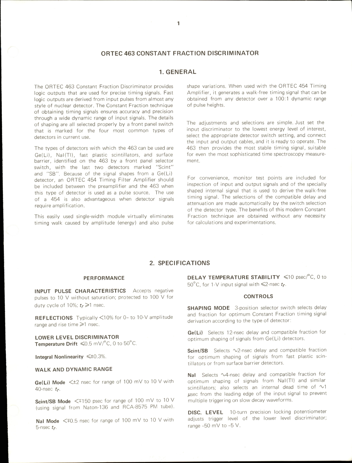
2.
SPECIFICATIONS
PERFORMANCE
INPUT
PULSE
CHARACTERISTICS
Accepts
negative
pulses
to
10
V
without
saturation:
protected
to
100
V
for
duty
cycle
of
10%;
f^^l
nsec.
REFLECTIONS
Typically
<10%
for
0-to
10-V
ampl
itude
range
and
rise
time
>1
nsec.
LOWER
LEVEL
DISCRIMINATOR
Temperature
Drift
<0.5
mV/°C,
0
to
50°C.
Integral
Nonllnearity
<±0.3%.
WALK
AND
DYNAMIC
RANGE
Ge(LI)
Mode
<±2
nsec
for
range
of
100
mV
to
10
V
with
40-nsec
tf.
Scint/SB
Mode
<+150
psec
for
range
of
100
mV
to
10
V
(using
signal
from
Naton-136
and
RCA-8575
PM
tube).
Nal
Mode
<+0.5
nsec
for
range
of
100
mV
to
10
V
with
5-nsec
t/-.
DELAY
TEMPERATURE
STABILITY
<10
psec/°C,
0
to
50°C,
for
TV
input
signal
with
<2-nsec
tr-
CONTROLS
SHAPING
MODE
3-position
selector
switch
selects
delay
and
fraction
for
optimum
Constant
Fraction
timing
signal
derivation
according
to
the
type
of
detector:
Ge(Li)
Selects
12-nsec
delay
and
compatible
fraction
for
optimum
shaping
of
signals
from
Ge(Li)
detectors.
Sclnt/SB
Selects
'v2-nsec
delay
and
compatible
fraction
for
optimum
shaping
of
signals
from
fast
plastic
scin
tillators
or
from
surface
barrier
detectors.
Nal
Selects
'V4-nsec
delay
and
compatible
fraction
for
optimum
shaping
of
signals
from
Nal(TI)
and
simi
lar
scintil
lators;
also
selects
an
internal
dead
time
of
lisec
from
the
leading
edge
of
the
input
signal
to
prevent
multiple
triggering
on
slow
decay
waveforms.
DISC.
LEVEL
10-turn
precision
locking
potentiometer
adjusts
trigger
level
of
the
lower
level
discriminator;
range
-50
mV
to
-5
V.
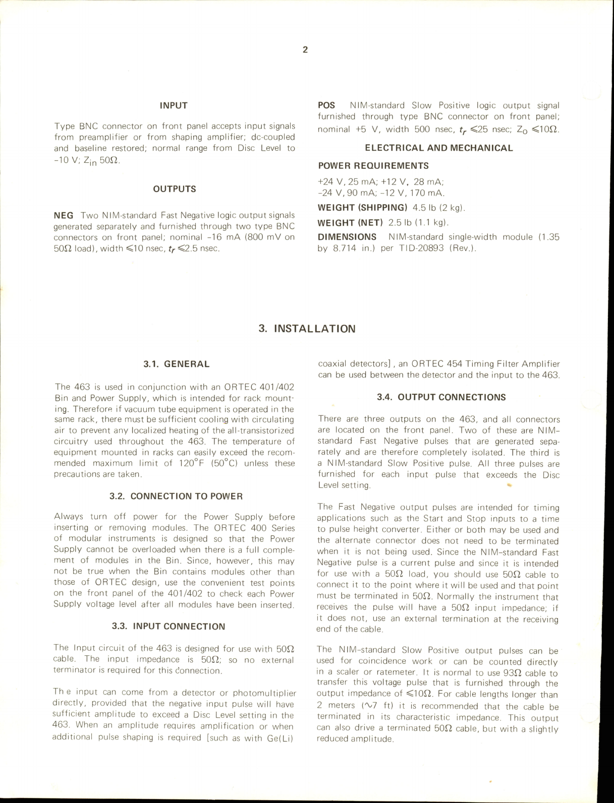
INPUT
Type
BNC
connector
on
front
panel
accepts
input
signals
from
preampl
ifier
or
from
shaping
amplifier;
dc-coupied
and
basel
ine
restored;
normal
range
from
Disc
Level
to
-10
V;
Z|n
50n.
OUTPUTS
NEC
Two
NIM-standard
Fast
Negative
logic
output
signals
generated
separately
and
furnished
through
two
type
BNC
connectors
on
front
panel
;
nominal
-16
mA
(800
mV
on
50fl
load),
width
<10
nsec,
f;-<2.5
nsec.
PCS
NIM-standard
Slow
Positive
logic
output
signal
furnished
through
type
BNC
connector
on
front
panel;
nominal
-i-5
V,
width
500
nsec,
tf
<25
nsec;
Zq
<10J2.
ELECTRICAL
AND
MECHANICAL
POWER
REQUIREMENTS
+24
V,
25
mA;
+12
V,
28
mA;
-24
V,90
mA;
-12
V,
170
mA.
WEIGHT
(SHIPPING)
4.5
lb
(2
kg).
WEIGHT
(NET)
2.5
lb
(1.1
kg).
DIMENSIONS
NIM-standard
single-width
module
(1.35
by
8.714
in.)
per
TID-20893
(Rev.).
3.
INSTALLATION
3.1.
GENERAL
The
463
is
used
in
conjunction
with
an
ORTEC
401/402
Bin
and
Power
Supply,
which
is
intended
for
rack
mount
ing.
Therefore
if
vacuum
tube
equipment
is
operated
in
the
same
rack,
there
must
be
sufficient
cool
ing
with
circulating
air
to
prevent
any
local
ized
heating
of
the
al
l-transistorized
circuitry
used
throughout
the
463.
The
temperature
of
equipment
mounted
in
racks
can
easily
exceed
the
recom
mended
maximum
l
imit
of
120°F
(50°C)
unless
these
precautions
are
taken.
3.2.
CONNECTION
TO
POWER
Always
turn
off
power
for
the
Power
Supply
before
inserting
or
removing
modules.
The
ORTEC
400
Series
of
modular
instruments
is
designed
so
that
the
Power
Supply
cannot
be
overloaded
when
there
is
a
ful
l
comple
ment
of
modules
in
the
Bin.
Since,
however,
this
may
not
be
true
when
the
Bin
contains
modules
other
than
those
of
ORTEC
design,
use
the
convenient
test
points
on
the
front
panel
of
the
401/402
to
check
each
Power
Supply
voltage
level
after
all
modules
have
been
inserted.
3.3.
INPUT
CONNECTION
The
Input
circuit
of
the
463
is
designed
for
use
with
50T2
cable.
The
input
impedance
is
50T2;
so
no
external
terminator
is
required
for
this
connection.
The
input
can
come
from
a
detector
or
photomultipl
ier
directly,
provided
that
the
negative
input
pulse
wi
l
l
have
sufficient
ampl
itude
to
exceed
a
Disc
Level
setting
in
the
463.
When
an
ampl
itude
requires
ampl
ification
or
when
additional
pulse
shaping
is
required
[such
as
with
Ge(Li)
coaxial
detectors]
,
an
ORTEC
454
Timing
Filter
Ampl
ifier
can
be
used
between
the
detector
and
the
input
to
the
463.
3.4.
OUTPUT
CONNECTIONS
There
are
three
outputs
on
the
463,
and
all
connectors
are
located
on
the
front
panel
.
Two
of
these
are
NIM-
standard
Fast
Negative
pulses
that
are
generated
sepa
rately
and
are
therefore
completely
isolated.
The
third
is
a
NIM-standard
Slow
Positive
pulse.
Al
l
three
pulses
are
furnished
for
each
input
pulse
that
exceeds
the
Disc
Level
setting.
The
Fast
Negative
output
pulses
are
intended
for
timing
appl
ications
such
as
the
Start
and
Stop
inputs
to
a
time
to
pulse
height
converter.
Either
or
both
may
be
used
and
the
alternate
connector
does
not
need
to
be
terminated
when
it
is
not
being
used.
Since
the
NIM-standard
Fast
Negative
pulse
is
a
current
pulse
and
since
it
is
intended
for
use
with
a
50r2
load,
you
should
use
50T2
cable
to
connect
it
to
the
point
where
it
wi
ll
be
used
and
that
point
must
be
terminated
in
50n.
Normal
ly
the
instrument
that
receives
the
pulse
will
have
a
50J2
input
impedance;
if
it
does
not,
use
an
external
termination
at
the
receiving
end
of
the
cable.
The
NIM-standard
Slow
Positive
output
pulses
can
be
used
for
coincidence
work
or
can
be
counted
directly
in
a
sealer
or
ratemeter.
It
is
normal
to
use
93Q
cable
to
transfer
this
voltage
pulse
that
is
furnished
through
the
output
impedance
of
<10J2.
For
cable
lengths
longer
than
2
meters
{^7
ft)
it
is
recommended
that
the
cable
be
terminated
in
its
characteristic
impedance.
This
output
can
also
drive
a
terminated
50n
cable,
but
with
a
sl
ightly
reduced
ampl
itude.
4.
OPERATION
After
the
463
has
been
instal
led
and
interconnected
as
described
in
Section
3,
the
only
operating
functions
that
are
required
are
the
setting
of
the
Mode
switch
and
an
adjustment
of
the
Disc
Level
control
.
Normal
ly
the
Mode
switch
can
be
set
at
the
switch
position
that
corresponds
to
the
type
of
detector
being
used.
Set
the
switch
at
Ge(Li)
for
signals
from
a
germanium
coaxial
detector;
set
it
at
Scint/SB
if
the
detector
is
either
a
fast
plastic
scintil
lator
or
a
surface
barrier
type;
or
set
it
at
Nal
for
use
with
a
slower
type
of
scintil
lator.
If
the
input
signal
to
the
463
is
furnished
from
a
signal
source
having
a
rise
time
that
is
longer
than
20
nsec,
the
Ge(Li)
switch
position
may
provide
more
satisfactory
operation
than
the
Scint/SB
position.
See
Section
7,
"Applications,"
for
further
suggestions.
The
function
of
the
Disc
Level
adjustment
is
to
permit
selection
of
signals
of
interest
and
to
eliminate
response
to
smal
ler
signals.
The
proper
setting
of
this
control
depends
on
the
range
of
signal
ampl
itudes
that
are
furnished
into
the
input.
The
range
is
from
-50
mV
to
-5
V
with
the
precision
10-turn
potentiometer
used
for
precise
setting
and
excellent
resettability.
5.
CIRCUIT
DESCRIPTION
The
signal
,
in
a
range
of
0
to
-10
V,
is
applied
through
Input
connector
CN1
and
routed
to
a
50f2
T
attenuator
consisting
of
R7, R8,
and
R9.
The
output
from
the
T
attenuator
has
half
of
the
input
signal
amplitude
and
is
l
imited
to
approximately
-6
V
and
+0.8
V
by
diodes
D2
and
D3.
The
signal
from
the
T
attenuator
goes
to
the
base
of
Q2
and
to
the
Shaping
Mode
switch,
81.
Q1
and
02
form
a
matched
pair
to
translate
the
zero
basel
ine
and
furnish
it
and
the
signal
into
a
fast
differential
comparator,
101.
When
the
signal
at
the
base
of
02
exceeds
the
level
selected
by
the
Disc
Level
control,
R11,
the
output
at
pin
8
of
101
switches
from
its
high
state
of
^^-0.8
V
to
its
low
state
of
'V-I.B
V.
The
low
state
is
appl
ied
to
pin
5
of
I04B
to
enable
the
And
gate
for
the
zero-crossing
signal
that
wil
l
come
from
102.
The
second
connection
for
the
output
from
the
T
attenuator
is
through
Shaping
Mode
switch
SI
.
For
each
switch-selected
shaping
mode
the
signal
is
spl
it
and
routed
through
an
attenuation
network
and
R19
to
the
base
of
Q3
and
through
a
delay
cable
DL1
and
R21
to
the
base
of
Q4.
The
switched
routing
provides
a
shaping
that
is
optimum
for
each
mode
selection.
For
Ge(Li)
the
signal
to
Q3
goes
through
R1
while
the
signal
for
Q4
goes
through
R2
and
DL2A.
For
Scint/SB,
the
signal
to
Q3
passes
through
R6
whi
le
the
signal
to
Q4
passes
through
R5.
For
Nal
the
signal
to
Q3
goes
through
R3
and
the
signal
to
Q4
goes
through
R4
and
DL3.
The
shaped
signals
through
the
matched
pair,
Q3
and
Q4,
are
applied
to
comparator
IC2.
When
zero-crossing
occurs,
the
signal
at
pin
8
of
IC2
shifts
to
the
low
state
and
is
applied
to
the
And
gate
IC4B
at
pin
4;
this
is
the
gate
that
has
been
enabled
to
accept
the
signal
by
the
out
put
from
IC1
.
The
output
from
IC2
is
also
buffered
through
IC4A
to
permit
osci
lloscope
observation
at
TP1.
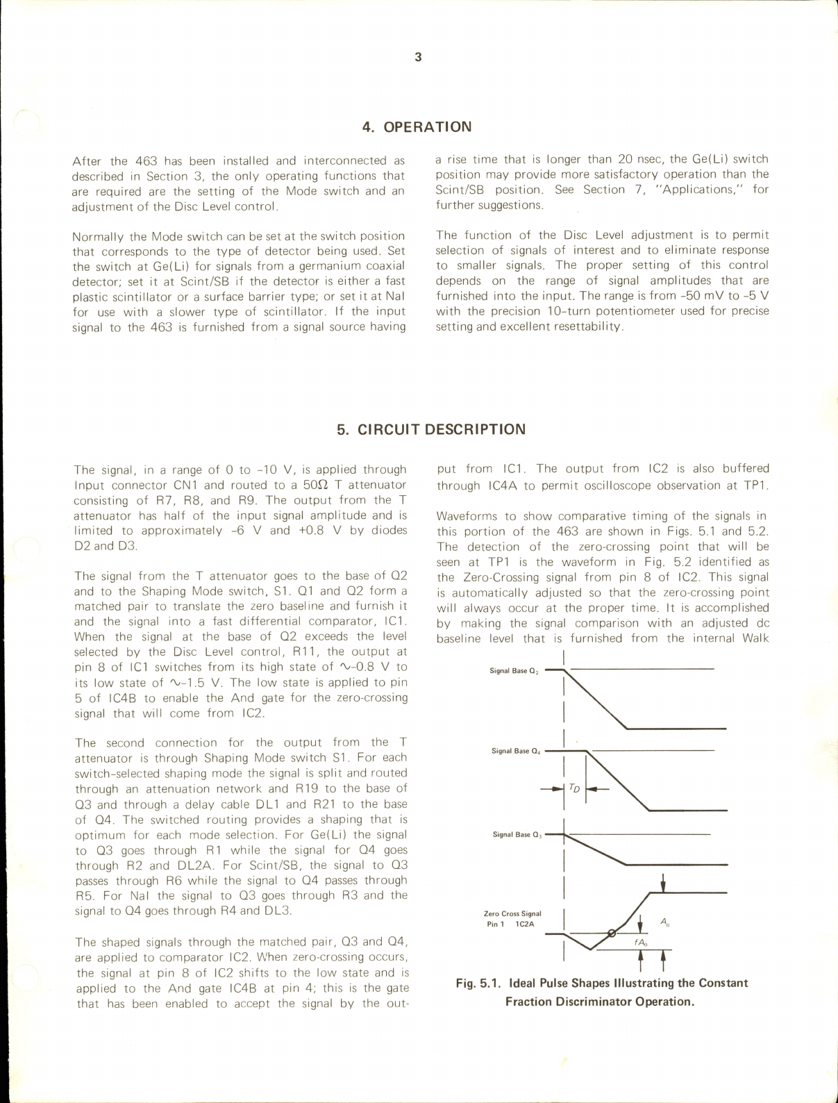
Waveforms
to
show
comparative
timing
of
the
signals
in
this
portion
of
the
463
are
shown
in
Figs.
5.1
and
5.2.
The
detection
of
the
zero-crossing
point
that
will
be
seen
at
TP1
is
the
waveform
in
Fig.
5.2
identified
as
the
Zero-Crossing
signal
from
pin
8
of
IC2.
This
signal
is
automatically
adjusted
so
that
the
zero-crossing
point
wil
l
always
occur
at
the
proper
time.
It
is
accompl
ished
by
making
the
signal
comparison
with
an
adjusted
dc
basel
ine
level
that
is
furnished
from
the
internal
Walk
Signal
Base
Q
Signal
Base
Q.
Signal
Base
Q
Zero
Cross
Signal
Pin
1
1C2A
Fig.
5.1.
Ideal
Pulse
Shapes
Illustrating
the
Constant
Fraction
Discriminator
Operation.
Level
Disc.
Output
-0.7V
(Pin
8.
IC1C)
Zero
Crossing
Signal
(Pin
8,
1C2C)
-1.5V
•0.7V
-0.7V
And
Output
Signal
(Pin
6,
IC4B}
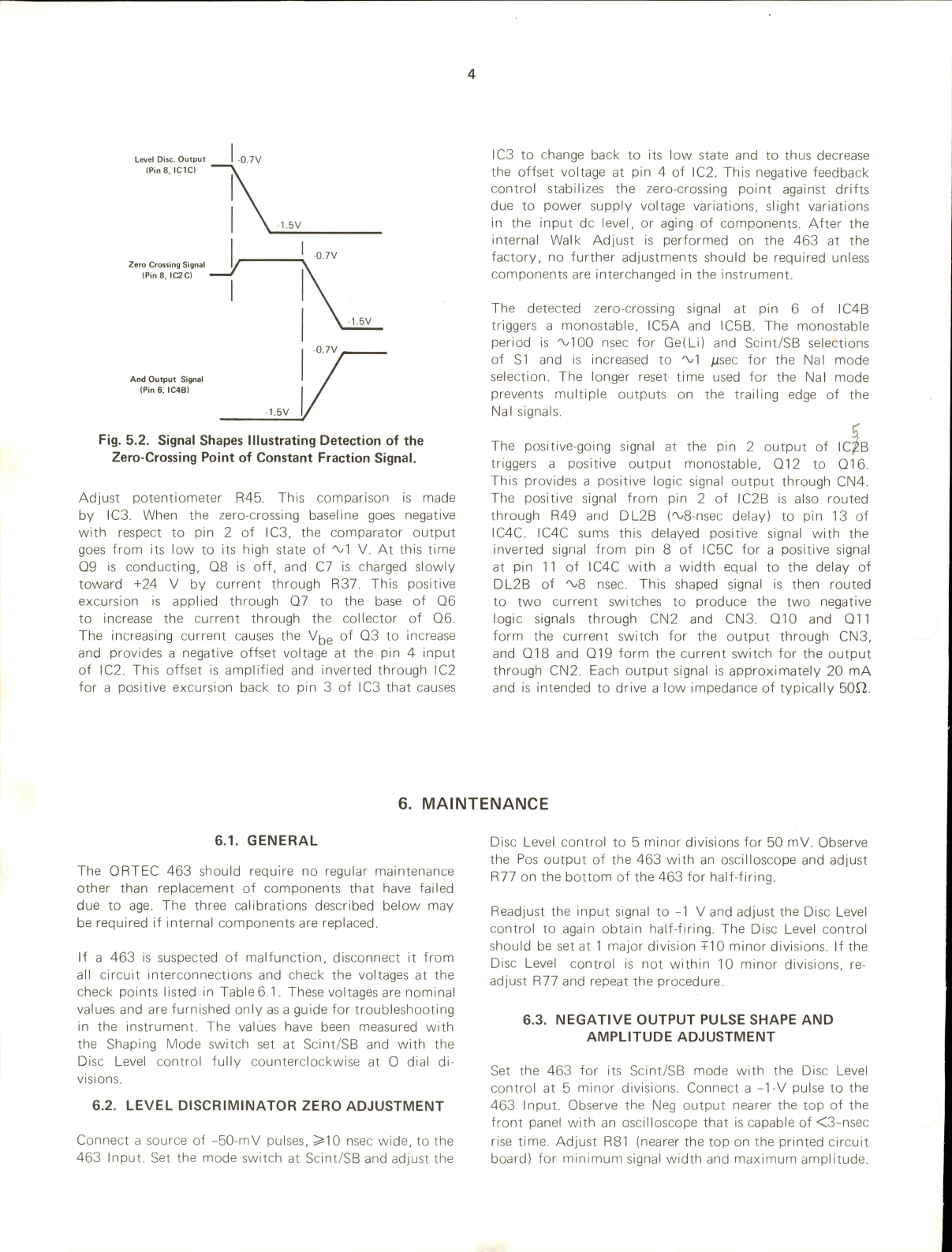
Fig.
5.2.
Signal
Shapes
Illustrating
Detection
of
the
Zero-Crossing
Point
of
Constant
Fraction
Signal.
Adjust
potentiometer
R45,
This
comparison
is
made
by
ICS.
When
the
zero-crossing
basel
ine
goes
negative
with
respect
to
pin
2
of
ICS,
the
comparator
output
goes
from
its
low
to
its
high
state
of
'Vl
V.
At
this
time
Q9
is
conducting,
Q8
is
off,
and
C7
is
charged
slowly
toward
+24
V
by
current
through
R37.
This
positive
excursion
is
applied
through
Q7
to
the
base
of
Q6
to
increase
the
current
through
the
col
lector
of
Q6.
The
increasing
current
causes
the
of
QS
to
increase
and
provides
a
negative
offset
voltage
at
the
pin
4
input
of
IC2,
This
offset
is
ampl
ified
and
inverted
through
IC2
for
a
positive
excursion
back
to
pin
S
of
ICS
that
causes
ICS
to
change
back
to
its
low
state
and
to
thus
decrease
the
offset
voltage
at
pin
4
of
IC2.
This
negative
feedback
control
stabilizes
the
zero-crossing
point
against
drifts
due
to
power
supply
voltage
variations,
sl
ight
variations
in
the
input
dc
level,
or
aging
of
components.
After
the
internal
Walk
Adjust
is
performed
on
the
46S
at
the
factory,
no
further
adjustments
should
be
required
unless
components
are
interchanged
in
the
instrument.
The
detected
zero-crossing
signal
at
pin
6
of
IC4B
triggers
a
monostable,
IC5A
and
IC5B.
The
monostable
period
is
'VlOO
nsec
for
Ge(Li)
and
Scint/SB
selections
of
SI
and
is
increased
to
'Vl
fxsec
for
the
Nal
mode
selection.
The
longer
reset
time
used
for
the
Nal
mode
prevents
multiple
outputs
on
the
trail
ing
edge
of
the
Nal
signals.
The
positive-going
signal
at
the
pin
2
output
of
IC^B
triggers
a
positive
output
monostable,
Q12
to
Q16.
This
provides
a
positive
logic
signal
output
through
CN4.
The
positive
signal
from
pin
2
of
IC2B
is
also
routed
through
R49
and
DL2B
('vS-nsec
delay)
to
pin
IS
of
IC4C.
IC4C
sums
this
delayed
positive
signal
with
the
inverted
signal
from
pin
8
of
IC5C
for
a
positive
signal
at
pin
11
of
IC4C
with
a
width
equal
to
the
delay
of
DL2B
of
'V8
nsec.
This
shaped
signal
is
then
routed
to
two
current
switches
to
produce
the
two
negative
logic
signals
through
CN2
and
CNS.
Q10
and
Q11
form
the
current
switch
for
the
output
through
CNS,
and
Q18
and
Q19
form
the
current
switch
for
the
output
through
CN2.
Each
output
signal
is
approximately
20
mA
and
is
intended
to
drive
a
low
impedance
of
typically
50^2.
6.
MAINTENANCE
6.1.
GENERAL
The
ORTEC
46S
should
require
no
regular
maintenance
other
than
replacement
of
components
that
have
failed
due
to
age.
The
three
cal
ibrations
described
below
may
be
required
if
internal
components
are
replaced.
If
a
46S
is
suspected
of
malfunction,
disconnect
it
from
al
l
circuit
interconnections
and
check
the
voltages
at
the
check
points
l
isted
in
Table
6.1.
These
voltages
are
nominal
values
and
are
furnished
only
as
a
guide
for
troubleshooting
in
the
instrument.
The
values
have
been
measured
with
the
Shaping
Mode
switch
set
at
Scint/SB
and
with
the
Disc
Level
control
ful
ly
counterclockwise
at
0
dial
di
visions.
6.2.
LEVEL
DISCRIMINATOR
ZERO
ADJUSTMENT
Connect
a
source
of
-50-mV
pulses,
>10
nsec
wide,
to
the
463
Input.
Set
the
mode
switch
at
Scint/SB
and
adjust
the
Disc
Level
control
to
5
minor
divisions
for
50
mV.
Observe
the
Pos
output
of
the
463
with
an
oscilloscope
and
adjust
R77
on
the
bottom
of
the
463
for
half-firing.
Readjust
the
input
signal
to
-1
V
and
adjust
the
Disc
Level
control
to
again
obtain
half-firing.
The
Disc
Level
control
should
be
set
at
1
major
division
+10
minor
divisions.
If
the
Disc
Level
control
is
not
within
10
minor
divisions,
re
adjust
R77
and
repeat
the
procedure.
6.3.
NEGATIVE
OUTPUT
PULSE
SHAPE
AND
AMPLITUDE
ADJUSTMENT
Set
the
463
for
Its
Scint/SB
mode
with
the
Disc
Level
control
at
5
minor
divisions.
Connect
a
-TV
pulse
to
the
463
Input.
Observe
the
Neg
output
nearer
the
top
of
the
front
panel
with
an
oscil
loscope
that
is
capable
of
<3-nsec
rise
time.
Adjust
R81
(nearer
the
top
on
the
printed
circuit
board)
for
minimum
signal
width
and
maximum
ampl
itude.

Table
6.1.
Typical
Voltages
at
Suggested
Check
Points
Check
Point
Voltage
Check
Point
Voltage
Q1E
-0.658
IC3,
pin
7
+1.622
Q1B
-0.002
IC3,
pin
8
+10.78
Q2E
-0.663
IC4,
pin
8
-0.756
Q2B
-0.008
IC4,
pin
9
-1.646
IC1,
pin
3
-1.110
IC4,
pin
12
-0.937
IC1,pin4
-1.327
IC4,
pin
13
-1.414
IC1,
pin
1
-1.749
IC5,pin
11
-1.026
IC1,
pin
2
-0.709
IC5,
pin
3
-1.937
IC1,
pin
8
-1.756
IC5,
pin
4
-0.947
Q3E
-0.671
IC5,
pin
1
-1.158
Q3B
-0.009
IC5,
pin
2
-1.412
Q4E
-0.673
IC5,
pin
6
-1.024
Q4B
-0.009
Q10E
-2.704
IC2,
pin
1
-1.149
Q10B
-1.933
IC2,
pin
2
-1.146
Q18E
-2.705
IC2,
pin
12
-1.179
Q12B
-0.120
IC2,
pin
13
-1.146
Q12C
+3.509
IC2,
pin
8
-1.124
Q13B
-0.344
Q5E
-12.61
Q14E
+2.729
Q6E
-12.00
Q15B
+0.651
Q6B
-11.35
Q15C
+0.428
Q8E
-10.70
Q17E
-5.875
Q8B
-16.59
Q17B
-6.504
Q8C
-10.69
Q17C
-10.82
Q9E
+0.647
-6
-5.547
IC3,
pin
3
-1.147
-6d
-5.306
IC3,
pin
4
-6.183
The
width
should
be
<10
nsec
and
the
amplitude
should
be
>0.7
V
into
a
50f2
load.
A
slow
oscil
loscope
wil
l
distort
both
the
ampl
itude
and
the
width.
Move
the
oscilloscope
connection
to
observe
the
Neg
out
put
nearer
the
bottom
of
the
front
panel
.
Repeat
the
above
procedure
and
adjust
R53
(nearer
the
bottom
on
the
printed
circuit
board)
for
the
optimum
signal
through
this
output.
6.4.
WALK
ADJUSTMENT
If
the
463
is
suspected
of
having
excessive
walk,
test
it
for
conformance
to
operating
standards
with
the
following
steps.
The
tests
are
outl
ined
separately
for
each
of
the
3
operating
modes
of
the
463.
Ge(Li)
Mode
Figure
6.1
shows
a
system
tfiat
can
be
used
to
check
the
463
walk
in
the
Ge(Li)
mode.
A
slow
rise-time
pulse,
'VIOO
nsec,
with
a
maximum
ampl
itude
of
about
-10
V
is
appl
ied
to
the
463
Input.
When
the
Neg
output
is
observed,
it
should
not
move
more
than
+2
nsec
with
respect
to
the
trigger
applied
to
the
oscil
loscope
for
any
combinations
of
XI, X2, X5,
and
X10
attenuator
settings
on
the
448
Pulser.
Scint/SB
Mode
Use
the
system
shown
in
the
block
diagram
of
Fig.
6.2
to
test
the
walk
of
the
463
in
its
Scint/SB
mode.
ORTEC
448
RESEARCH
PULSER
Negative
Polarity
RG-58
Cable
Direct
Output
loon
Attenuated
Output
ORTEC
454
TIMING
FILTER
AMPLIFIER
Coarse
Gain:
5
Fine
Gain:
2
lot:
100
nsec
Diff:
100
nsec
Input
Polarity:
Neg
TEKTRONIX
454
OSCILLOSCOPE
0.5
V/div
5
nsec/div
Ext
Trigger
ORTEC
463
CONSTANT
FRACTION
DISCRIMINATOR
Shaping
Mode:
Ge(Li)
Disc
Level:
5
(minor
div)
Fig.
6.1.
Block
Diagram
of
System
for
Walk
Test
of
the
ORTEC
463
In
the
Ge(LI)
Mode.
RG-58
Cable
RG-58
Cable
TRIGGER
50<>
TEKTRONIX
SO'i
ATTENUATOR
X2,X5,
X10
ORTEC
463
CONSTANT
FRACTION
DISCRIMINATOR
Shaping
Mode:
Ge(Li)
Disc
Level:
5
(minor
div)
TEKTRONIX
454
OSCILLOSCOPE
0.5
V/div
5
nsec/div
Ext
Trigger
Rep.
Rate:
Pulse
Width:
Amplitude:
Output
Polarity:
Neg.
1000
10
n
HP-8004
A
PULSER
sec
5
V
Fig.
6.2.
Block
Diagram
of
System
for
Walk
Test
of
the
ORTEC
463
In
the
Scint/SB
Mode.
For
any
combination
of
attenuator
settings
of
XI,X2,X5,
and
XI0
(but
not
for
XI00)
the
observed
walk
should
be
less
than
+0.15
of
a
minor
division
on
the
oscil
loscope.
A
more
precise
measurement
can
be
made
if
a
time
base
of
1
nsec/division
is
available.
This
time
base
is
available
on
Tektronix
454A
real
time
oscilloscopes
and
on
sampl
ing
oscilloscopes.
A
dynamic
range
of
only
50:1
has
been
suggested
because
the
FIP8004A
provides
a
maximum
output
ampl
itude
of
5
V.
If
a
pulser
is
available
with
a

rise
time
of
<2
nsec
and
an
ampl
itude
of
10
V,
the
463
walk
should
be
tested
for
the
range
of
10
V
to
100
mV.
Be
careful
when
making
this
measurement
to
consider
the
Tektronix
Attenuator
characteristics.
It
is
not
uncommon
for
an
insertion
delay
variation
of
+100
psec
to
exist
in
the
attenuator.
Verify
the
delay
consistency
of
the
attenuator
before
making
the
walk
test,
since
100
psec
is
equivalent
to
<1/8-inch
difference
in
signal
path
length
and
is
l
ikely
to
exist
for
most
attenuator
units.
Na!
Mode
This
test
is
identical
to
the
procedure
outl
ined
for
Scint/SB
mode
except
that
the
rise
time
of
the
signal
to
the
463
should
be
about
5
nsec
to
simulate
more
closely
the
signal
from
a
Nal
scinti
llator.
The
walk
should
not
exceed
+0.5
nsec
in
this
mode
for
a
range
of
input
pulse
heights
from
10
V
to
100
mV.
Walk
Correction
If
the
unit
fails
to
meet
the
walk
test
as
outl
ined
above,
a
correction
can
be
made.
This
adjustment
has
been
made
at
the
factory
and
should
not
normal
ly
be
necessary
unless
some
components
have
been
replaced
due
to
failure.
Use
the
fol
lowing
procedure:
1.
Connect
the
463
into
the
system
shown
in
Fig.
6.2
and
set
the
Tektronix
50J2
Attenuator
for
XI.
Move
the
cable
for
the
osci
l
loscope
input
signal
to
TPI
on
the
top
of
the
463
and
use
a
X10
attenuated
probe.
2.
Adjust
R45
clockwise
until
the
signal
is
similar
to
that
of
Fig.
6.3a.
3.
Adjust
R45
counterclockwise
until
the
signal
is
similar
to
that
of
Fig.
6.3b.
4.
Adjust
R45
clockwise
again
until
the
signal
at
TPI
is
correct
as
shown
in
Fig.
6.3c.
This
provides
a
first-order
adjustment
and
is
usual
ly
sufficient
for
proper
walk
characteristics.
If
a
finer
adjust
ment
is
necessary
to
minimize
the
walk,
use
the
exact
system
in
Fig.
6.2.
Set
the
attenuator
to
X50
and
adjust
R45
(less
than
+1
turn)
so
that
the
time
walk
is
zero.
After
this
adjustment
the
463
should
meet
the
walk
test
suggested
for
al
l
three
modes.
0
1 1
1
1
1
N
/
-
/
1
1
1
1
1
1 1
1
-tHT
rt
t
r
11
1 1
1
1
1 1
1
1
1 1
1
M
1 1
1 1 1
(a)
R45
Too
Far
Clockwise
(b)
R45
Too
Far
Counterclockwise
1
1
1 1
1
1
1
r
M
41
1
1
1 1
4444-
4444
1 1 1 1
Vert.
0.5
V
/div
Horiz.
5
nsec/div
1
1
(c)
Correct
Adjustment
Fig.
6.3.
Effect
of
Walk
Adjustment
In
the
ORTEC
463.
7.
APPLICATIONS
7.1.
TIMING
WITH
FAST
SCINTILLATORS
7.2.
TIMING
WITH
LARGE
Ge(Li)
DETECTORS
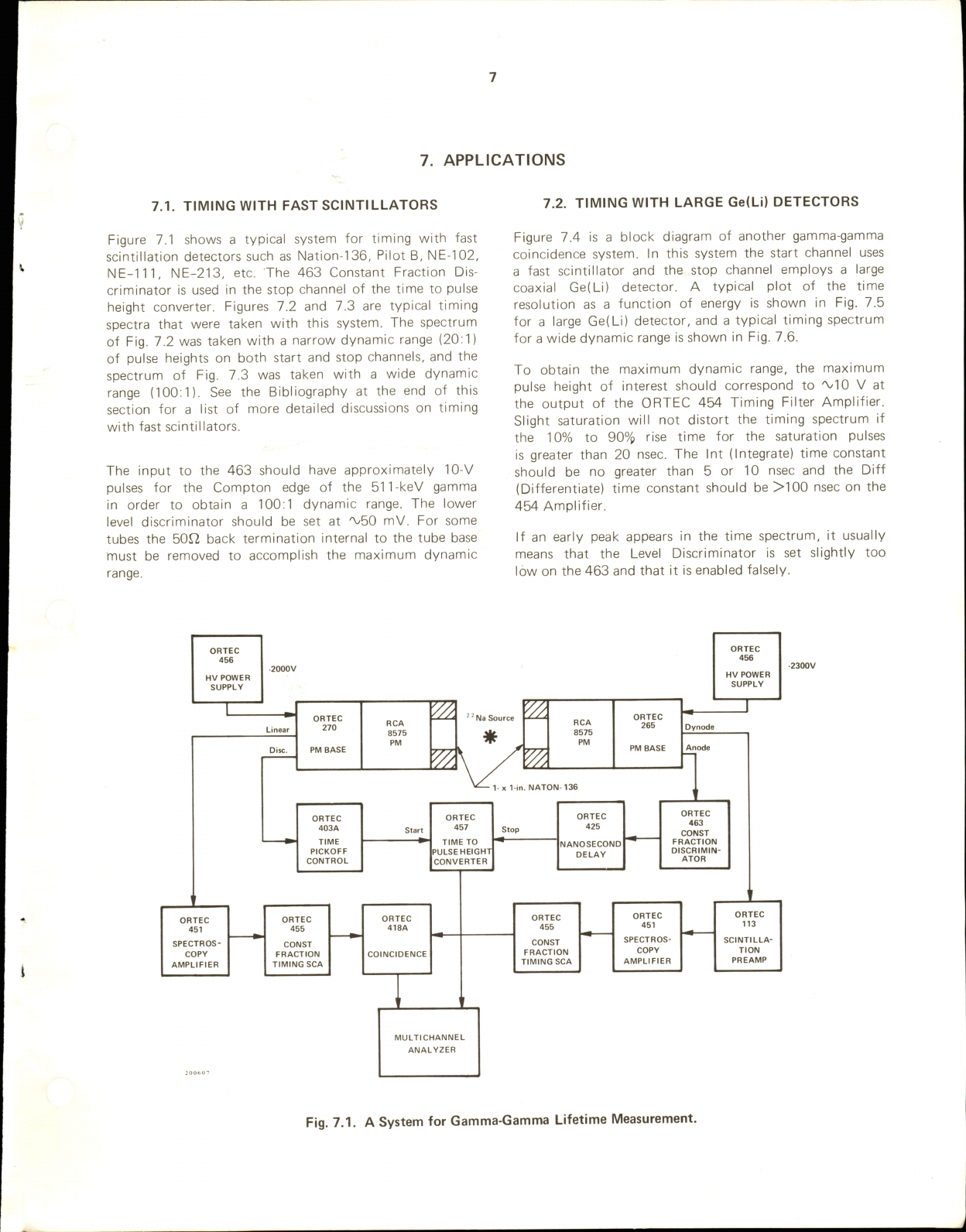
Figure
7.1
shows
a
typical
system
for
timing
with
fast
scintil
lation
detectors
such
as
Nation-136,
Pi
lot
B,
NE-102,
NE-111, NE-213,
etc.
The
463
Constant
Fraction
Dis
criminator
is
used
in
the
stop
channel
of
the
time
to
pulse
height
converter.
Figures
7.2
and
7.3
are
typical
timing
spectra
that
were
taken
with
this
system.
The
spectrum
of
Fig.
7.2
was
taken
with
a
narrow
dynamic
range
(20:1)
of
pulse
heights
on
both
start
and
stop
channels,
and
the
spectrum
of
Fig.
7.3
was
taken
with
a
wide
dynamic
range
(100:1).
See
the
Bibl
iography
at
the
end
of
this
section
for
a
l
ist
of
more
detailed
discussions
on
timing
with
fast
scintil
lators.
The
input
to
the
463
should
have
approximately
10-V
pulses
for
the
Compton
edge
of
the
51
TkeV
gamma
in
order
to
obtain
a
100:1
dynamic
range.
The
lower
level
discriminator
should
be
set
at
'V50
mV.
For
some
tubes
the
50^2
back
termination
internal
to
the
tube
base
must
be
removed
to
accomplish
the
maximum
dynamic
range.
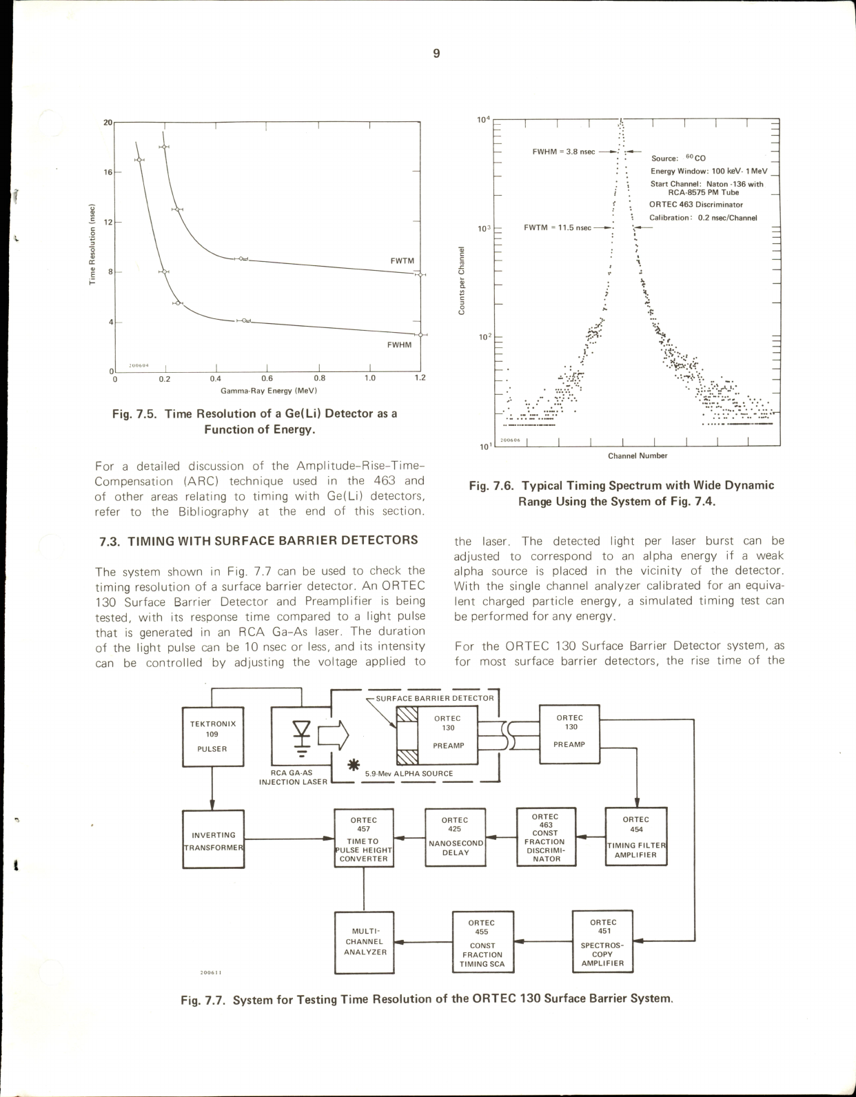
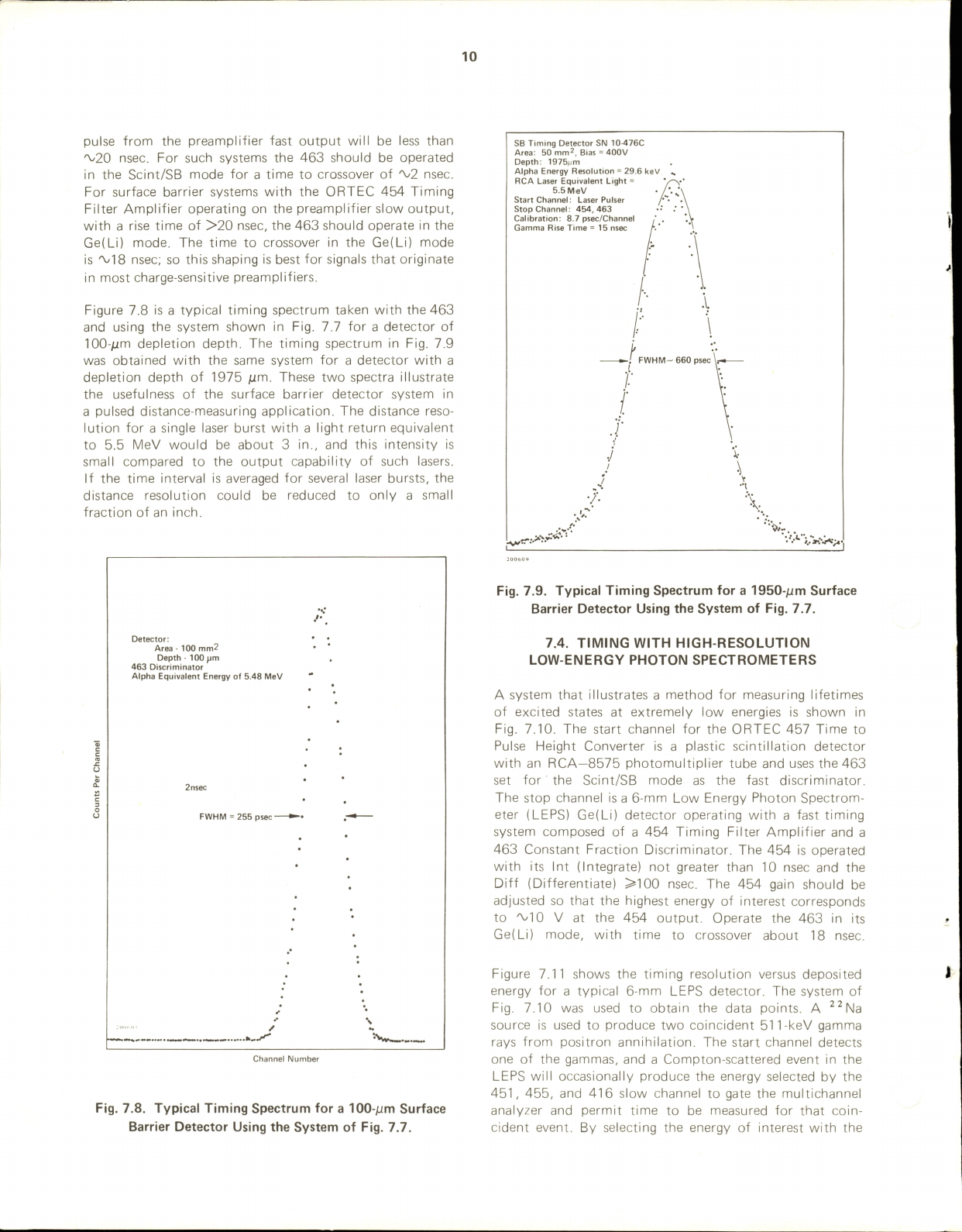
Figure
7.4
is
a
block
diagram
of
another
gamma-gamma
coincidence
system.
In
this
system
the
start
channel
uses
a
fast
scinti
llator
and
the
stop
channel
employs
a
large
coaxial
Ge(Li)
detector.
A
typical
plot
of
the
time
resolution
as
a
function
of
energy
is
shown
in
Fig.
7.5
for
a
large
Ge(Li)
detector,
and
a
typical
timing
spectrum
for
a
wide
dynamic
range
is
shown
in
Fig.
7.6.
To
obtain
the
maximum
dynamic
range,
the
maximum
pulse
height
of
interest
should
correspond
to
'ViO
V
at
the
output
of
the
ORTEC
454
Timing
Filter
Amplifier.
Sl
ight
saturation
wi
l l
not
distort
the
timing
spectrum
if
the
10%
to
90%
rise
time
for
the
saturation
pulses
is
greater
than
20
nsec.
The
Int
(Integrate)
time
constant
should
be
no
greater
than
5
or
10
nsec
and
the
Diff
(Differentiate)
time
constant
should
be
>100
nsec
on
the
454
Amplifier.
If
an
early
peak
appears
in
the
time
spectrum,
it
usual
ly
means
that
the
Level
Discriminator
is
set
slightly
too
low
on
the
463
and
that
it
is
enabled
falsely.
ORTEC
456
HV
POWER
SUPPLY
ORTEC
403A
TIME
PICKOFF
CONTROL
270
RCA
8575
PM
BASE
PM
Va
a
Source
*
Va
ORTEC
265
RCA
8575
PM
PM
BASE
l-x
1-in.
NATON-136
ORTEC
457
TIME
TO
PULSE
HEIGHT
CONVERTER
ORTEC
451
ORTEC
455
ORTEC
418A
SPECTROS-
CONST
COPY
FRACTION
COINCIDENCE
AMPLIFIER
TIMING
SCA
Stop
ORTEC
425
NANOSECOND
DELAY
ORTEC
455
CONST
FRACTION
TIMING
SCA
ORTEC
451
SPECTROS-
COPY
AMPLIFIER
MULTICHANNEL
ANALYZER
ORTEC
456
HV
POWER
SUPPLY
Dynode
ORTEC
463
CONST
FRACTION
DISCRIMIN
ATOR
ORTEC
113
SCINTILLA
TION
PREAMP
Fig.
7.1.
A
System
for
Gamma-Gamma
Lifetime
Measurement.

40,000
Calibration:
17.5
psec/Channel
Duration
of
Run:
5
hr
Source:
■'
Na
Dynamic
Range:
20%
-
FWHM
380
psec-
&
2000
1000
600
400
Start
Channel:
1-
by
1-in.
Naton-136,
RCA-8575
PM
Tube,
ORTEC
270
CFPHT
Base.
Stop
Channel:
1-
by
1-in.
Naton-136,
RCA-8575
PM
Tube,
ORTEC
463
Constant
Fraction
Discriminator
FWTM
735
psec
340
360
Channel
Number
Fig.
7.2.
Timing
Over
a
Narrow
Dynamic
Range
with
the
System
of
Fig.
7.1.
Calibration:
87.5
psec/channel
Source:
^
^
Na
Dynamic
Range:
100:1
l^max
~
340
kev)
FWHM
=
480
psec
FWTM
=
1.15
nsec
Start
Channel:
1-
by
Tin.
Naton-136,
RCA-8575
PM
Tube
ORTEC
270
CFPHT
Base
Stop
Channel
:
1-
by
1-in.
Naton-136,
RCA-8575
PM
Tube
ORTEC
463
Constant
Fraction
Discriminator
330 335 340
Channel
Number
Fig.
7.3.
Timing
Over
a
Wide
Dynamic
Range
with
the
System
of
Fig.
7.1.
2-
by
2-in.
Naton
136
ORTEC
456
HV
POWER
SUPPLY
ORTEC
463
CONST
FRACTION
DISCRIMI
NATOR
ORTEC
RCA
265
8575
PM
BASE
PM
TUBE
ORTEC
120
Ge
Li
45CC
PREAMP
Na
Source
ORTEC
416A
GATE
AND
DELAY
GENERATOR
ORTEC
455
CONST
FRACTION
TIMING
SCA
ORTEC
452
SPECTROS-
COPY
AMPLIFIER
ORTEC
457
TIME
TO
PULSE
HEIGHT
CONVERTER
ORTEC
425
NANOSECOND
DELAY
ORTEC
463
CONST
FRACTION
DISCRIMI
NATOR
ORTEC
459
DETECTOR
BIAS
SUPPLY
ORTEC
454
TIMING
FILTER
AMPLIFIER
MULTI
CHANNEL
ANALYZER
Fig.
7.4.
Gamma-Gamma
Coincidence
System
Using
Plastic
Scintillator
and
a
Large
Ge(Li)
Coaxial
Detector.
0
0.2
0.4
0.6
0.8
1.0
Gamma-Ray
Energy
(MeV)
Fig.
7.5.
Time
Resolution
of
a
Ge(Li)
Detector
as
a
Function
of
Energy.
For
a
detai
led
discussion
of
the
Ampl
itude-Rise-Time-
Compensation
(ARC)
technique
used
in
the
463
and
of
other
areas
relating
to
timing
with
Ge(Li)
detectors,
refer
to
the
Bibl
iography
at
the
end
of
this
section.
FWHM
=3.8
nsec
-
FWTM
=11.5
nsec-
1—q
Source:
""CO
Energy
Window:
100
keV-1
MeV
Start
Channel:
Naton
-136
with
RCA-8575
PM
Tube
ORTEC
463
Discriminator
Calibration:
0.2
nsec/Channel
'•W.t
Channel
Number
Fig.
7.6.
Typical
Timing
Spectrum
with
Wide
Dynamic
Range
Using
the
System
of
Fig.
7.4.
7.3.
TIMING
WITH
SURFACE
BARRIER
DETECTORS
The
system
shown
in
Fig.
7.7
can
be
used
to
check
the
timing
resolution
of
a
surface
barrier
detector.
An
ORTEC
130
Surface
Barrier
Detector
and
Preampl
ifier
is
being
tested,
with
its
response
time
compared
to
a
l
ight
pulse
that
is
generated
in
an
RCA
Ga-As
laser.
The
duration
of
the
light
pulse
can
be
10
nsec
or
less,
and
its
intensity
can
be
controlled
by
adjusting
the
voltage
appl
ied
to
the
laser.
The
detected
light
per
laser
burst
can
be
adjusted
to
correspond
to
an
alpha
energy
if
a
weak
alpha
source
is
placed
in
the
vicinity
of
the
detector.
With
the
single
channel
analyzer
calibrated
for
an
equiva
lent
charged
particle
energy,
a
simulated
timing
test
can
be
performed
for
any
energy.
For
the
ORTEC
130
Surface
Barrier
Detector
system,
as
for
most
surface
barrier
detectors,
the
rise
time
of
the
TEKTRONIX
109
PULSER
RCA
GA-AS
INJECTION
LASER
ORTEC
457
TIMETO
PULSE
HEIGHT
CONVERTER
MULTI
CHANNEL
ANALYZER
SURFACE
BARRIER
DETECTOR
ORTEC
ORTEC
130
ZIC^
130
PREAMP
))
PREAMP
5.9-Mev
ALPHA
SOURCE
INVERTING
TRANSFORMER
ORTEC
425
NANOSECOND
DELAY
ORTEC
455
CONST
FRACTION
TIMING
SCA
ORTEC
463
CONST
FRACTION
DISCRIMI
NATOR
ORTEC
454
TIMING
FILTER
AMPLIFIER
ORTEC
451
SPECTROS-
COPY
AMPLIFIER
Fig.
7.7.
System
for
Testing
Time
Resolution
of
the
ORTEC
130
Surface
Barrier
System.
10
pulse
from
the
preamplifier
fast
output
wi
ll
be
less
than
'V20
nsec.
For
such
systems
the
463
should
be
operated
in
the
Scint/SB
mode
for
a
time
to
crossover
of
"^2
nsec.
For
surface
barrier
systems
with
the
ORTEC
454
Timing
Filter
Ampl
ifier
operating
on
the
preampl
ifier
slow
output,
with
a
rise
time
of
>20
nsec,
the
463
should
operate
in
the
Ge(Li)
mode.
The
time
to
crossover
in
the
Ge(Li)
mode
is
'V/IS
nsec;
so
this
shaping
is
best
for
signals
that
originate
in
most
charge-sensitive
preampl
ifiers.
Figure
7.8
is
a
typical
timing
spectrum
taken
with
the
463
and
using
the
system
shown
in
Fig.
7.7
for
a
detector
of
100-/L(m
depletion
depth.
The
timing
spectrum
in
Fig.
7.9
was
obtained
with
the
same
system
for
a
detector
with
a
depletion
depth
of
1975
/jm.
These
two
spectra
illustrate
the
usefulness
of
the
surface
barrier
detector
system
in
a
pulsed
distance-measuring
appl
ication.
The
distance
reso
lution
for
a
single
laser
burst
with
a
light
return
equivalent
to
5.5
MeV
would
be
about
3
in.,
and
this
intensity
is
smal
l
compared
to
the
output
capabil
ity
of
such
lasers.
If
the
time
interval
is
averaged
for
several
laser
bursts,
the
distance
resolution
could
be
reduced
to
only
a
smal
l
fraction
of
an
inch.
/\
Detector:
•
•
Area
•
100
mm2
•
Depth
•
100
pm
,
463
Discriminator
Alpha
Equivalent
Energy
of
5.48
MeV
^
•
2
nsec
•
FWHM
=
255
psec
•
<
\
/
••
..
N-v
Channel
Number
SB
Timing
Detector
SN
10-4760
Area;
50
mm^.
Bias
=
400V
Depth:
1975Aim
Alpha
Energy
Resolution
=
29.6
keV
^
RCA
Laser
Equivalent
Light
=
y-y
5.5
MeV
•
/*.
Start
Channel:
Laser
Pulser
/•**•
i
Stop
Channel:
454,463
••
Calibration:
8.7
psec/Channel
Gamma
Rise
Time
=
15
nsec
FWHM'-'
660
psec
\
y
\
.•vC
Fig.
7.8.
Typical
Timing
Spectrum
for
a
100-/im
Surface
Barrier
Detector
Using
the
System
of
Fig.
7.7.
Fig.
7.9.
Typical
Timing
Spectrum
for
a
1950-/im
Surface
Barrier
Detector
Using
the
System
of
Fig.
7.7.
7.4.
TIMING
WITH
HIGH-RESOLUTION
LOW-ENERGY
PHOTON
SPECTROMETERS
A
system
that
i
llustrates
a
method
for
measuring
l
ifetimes
of
excited
states
at
extremely
low
energies
is
shown
in
Fig.
7.10.
The
start
channel
for
the
ORTEC
457
Time
to
Pulse
Fleight
Converter
is
a
plastic
scintillation
detector
with
an
RCA—8575
photomultiplier
tube
and
uses
the
463
set
for
the
Scint/SB
mode
as
the
fast
discriminator.
The
stop
channel
is
a
6-mm
Low
Energy
Photon
Spectrom
eter
(LEPS)
Ge(Li)
detector
operating
with
a
fast
timing
system
composed
of
a
454
Timing
Filter
Amplifier
and
a
463
Constant
Fraction
Discriminator.
The
454
is
operated
with
its
Int
(Integrate)
not
greater
than
10
nsec
and
the
□iff
(Differentiate)
>100
nsec.
The
454
gain
should
be
adjusted
so
that
the
highest
energy
of
interest
corresponds
to
'V'lO
V
at
the
454
output.
Operate
the
463
in
its
Ge(Li)
mode,
with
time
to
crossover
about
18
nsec.
Figure
7.11
shows
the
timing
resolution
versus
deposited
energy
for
a
typical
6-mm
LEPS
detector.
The
system
of
Fig.
7.10
was
used
to
obtain
the
data
points.
A
^^Na
source
is
used
to
produce
two
coincident
511-keV
gamma
rays
from
positron
annihilation.
The
start
channel
detects
one
of
the
gammas,
and
a
Compton-scattered
event
in
the
LEPS
wil
l
occasional
ly
produce
the
energy
selected
by
the
451,
455,
and
416
slow
channel
to
gate
the
multichannel
analyzer
and
permit
time
to
be
measured
for
that
coin
cident
event.
By
selecting
the
energy
of
interest
with
the

11
ORTEC
456
HV
POWER
SUPPLY
2-
by
2
in.
Naton
136
RCA
8575
/
ORTEC
124
265
/
*
Ge(Li)
PM
BASE
PM
TUBE
6-mm
PREAMP
^
*
Na
Source
ORTEC
463
CONST
FRACTION
DISCRIMI
NATOR
ORTEC
457
Stop
ORTEC
425
TIME
TO
PULSE
HEIGHT
CONVERTER
NANOSECOND
DELAY
i
ORTEC
442
ORTEC
416A
LINEAR
GATE
AND
STRETCHER
GATE
AND
DELAY
GENERATOR
ORTEC
463
CONST
FRACTION
DISCRIMI
NATOR
ORTEC
455
CONST
FRACTION
TIMING
SCA
ORTEC
454
TIMING
FILTER
AMPLIFIER
ORTEC
451
SPECTROS-
COPY
AMPLIFIER
ORTEC
456
HV
POWER
SUPPLY
MULTI
CHANNEL
ANALYZER
Fig.
7.10.
Fast
Coincidence
System
Using
a
Gel
Li)
6-mm
Low
Energy
Photon
Spectrometer.
80
120
Energy
(keV)
Fig.
7.11.
Time
Resolution
vs
Energy
for
a
6-mm
Low
Energy
Photon
Spectrometer.
451
and
455,
the
Compton
scattering
can
produce
a
timing
spectrum
at
the
desired
energy.
The
system
with
the
block
diagram
in
Fig.
7.10
can
also
be
used
for
a
l
ifetime
measurement
of
an
excited
state.
A
typical
example
is
seen
in
the
decay
from
the
136-keV
state
of
'''Co.
The
decay
from
the
136-keV
state
to
the
ground
state
is
by
way
of
122
keV
to
a
14-keV
state,
and
the
electron
has
an
approximate
100-nsec
lifetime
in
the
14-keV
state.
Thus
the
start
channel
can
be
activated
by
the
122-keV
gamma
ray,
and
the
slow
channel
of
the
stop
side
can
be
adjusted
to
observe
only
the
14-keV
gamma
ray:
the
l
ifetime
of
the
14-keV
state
can
then
be
measured
and
recorded.
A
spectrum
showing
typical
results
of
this
measurement
is
shown
in
Fig.
7.12.
7.5.
TIMING
WITH
Nal(TI)
SCINTILLATORS
This
type
of
measurement
is
similar
to
timing
with
fast
scintil
lators
except
for
one
additional
problem
that
must
be
considered.
The
photoelectron
statistics
are
so
poor
for
low-energy
gamma-ray
work
that
individual
photoelectron
events
near
the
trail
ing
edge
of
the
Nal(TI)
pulses
will
trigger
the
463.
Thus
a
single
scintillation
event
can
10,000
7,000
4,000
Z
1,000
o
700
280
psec/Channel
200
600
800
Channel
Number
1,000 1,200
1,400
Fig.
7.12.
Spectrum
of
the
Lifetime
of
the
14-keV
State
in
the
Decay
of
"
Co.
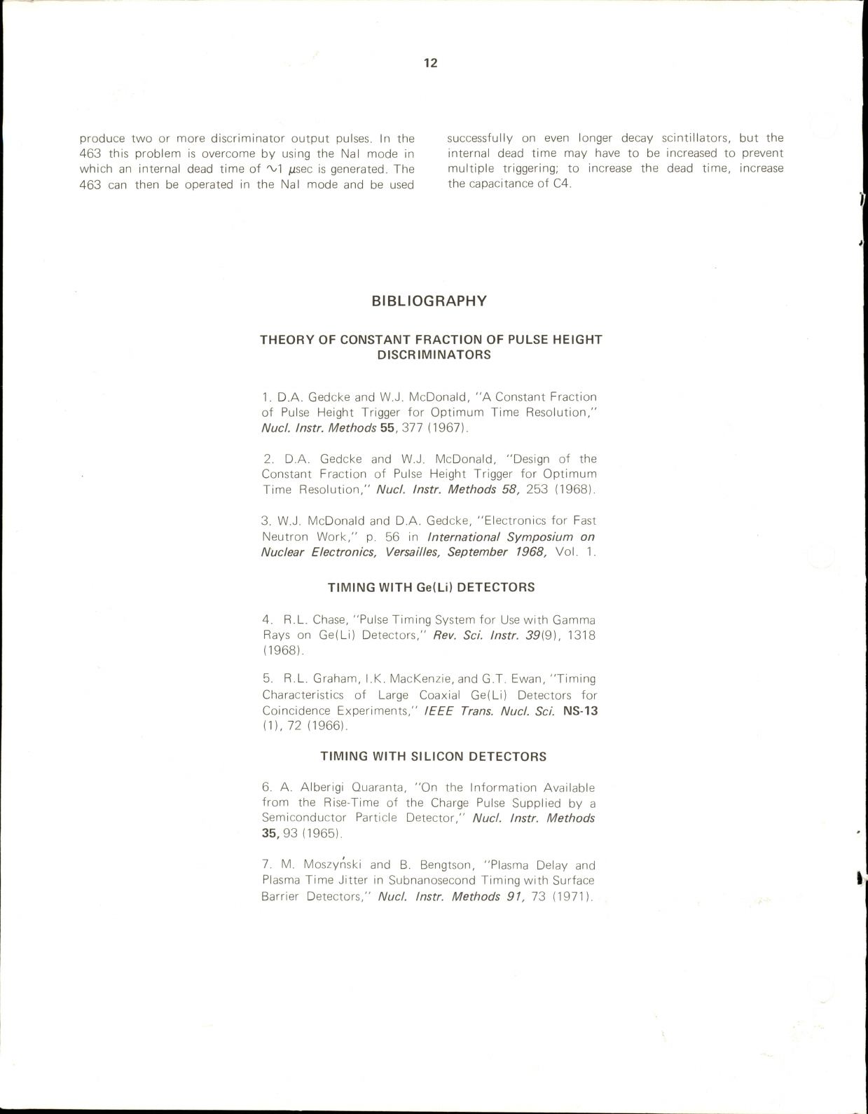
12
produce
two
or
more
discriminator
output
pulses.
In
the
successful
ly
on
even
longer
decay
scintillators,
but
the
463
this
problem
is
overcome
by
using
the
Nal
mode
in
internal
dead
time
may
have
to
be
increased
to
prevent
which
an
internal
dead
time
of
'vl
jisec
is
generated.
The
multiple
triggering;
to
increase
the
dead
time,
increase
463
can
then
be
operated
in
the
Nal
mode
and
be
used
the
capacitance
of
C4.
BIBLIOGRAPHY
THEORY
OF
CONSTANT
FRACTION
OF
PULSE
HEIGHT
DISCRIMINATORS
1.
D.A.
Gedcke
and
W.J.
McDonald,
"A
Constant
Fraction
of
Pulse
Height
Trigger
for
Optimum
Time
Resolution,"
Nucl.
Instr.
Methods
55,
377
(1967).
2.
D.A.
Gedcke
and
W.J.
McDonald,
"Design
of
the
Constant
Fraction
of
Pulse
Height
Trigger
for
Optimum
Time
Resolution,"
Nud.
Instr.
Methods
58,
253
(1968).
3.
W.J.
McDonald
and
D.A.
Gedcke,
"Electronics
for
Fast
Neutron
Work,"
p.
56
in
International
Symposium
on
Nuclear
Electronics,
Versailles,
September
1968,
Vol
.
1.
TIMING
WITH
Ge(Li)
DETECTORS
4.
R.L.
Chase,
"Pulse
Timing
System
for
Use
with
Gamma
Rays
on
Ge(Li)
Detectors,"
Rev.
Sci.
Instr.
39{9),
1318
(1968).
5.
R.L.
Graham,
I
.K.
MacKenzie,
and
G.T.
Ewan,
"Timing
Characteristics
of
Large
Coaxial
Ge(Li)
Detectors
for
Coincidence
Experiments,"
IEEE
Trans.
Nud.
Sci.
NS-13
(1)
,
72
(1966).
TIMING
WITH
SILICON
DETECTORS
6.
A.
Alberigi
Quaranta,
"On
the
Information
Available
from
the
Rise-Time
of
the
Charge
Pulse
Suppl
ied
by
a
Semiconductor
Particle
Detector,"
Nud.
instr.
Methods
35,
93
(1965).
7.
M.
Moszynski
and
B.
Bengtson,
"Plasma
Delay
and
Plasma
Time
Jitter
in
Subnanosecond
Timing
with
Surface
Barrier
Detectors,"
Nud.
Instr.
Methods
91,
73
(1971).
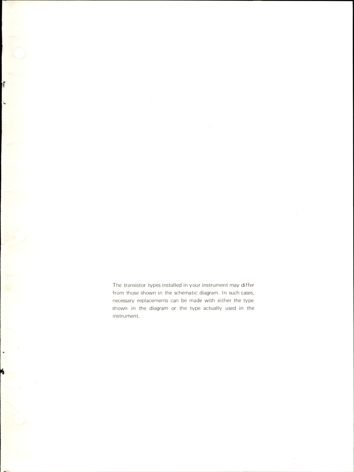
The
transistor
types
installed
in
your
instrument
may
differ
from
those
shown
in
the
schematic
diagram.
In
such
cases,
necessary
replacements
can
be
made
with
either
the
type
shown
in
the
diagram
or
the
type
actually
used
in
the
instrument.
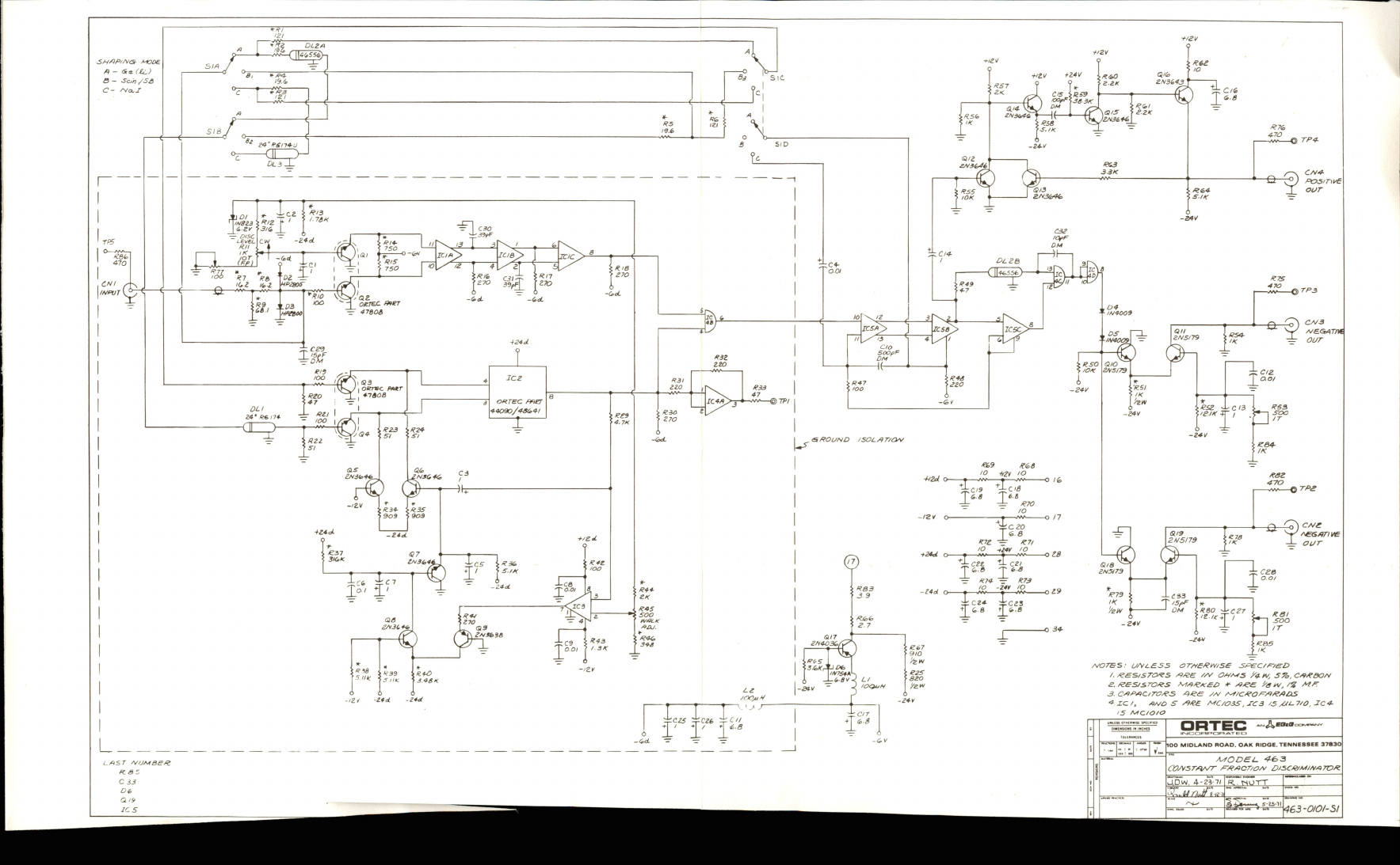
3H/1P'/y<Sr
AtOOe
A
-
(Ss
(Ic)
B
—
s5c/>j
/SS
C~
/\a.X
"Xf^SSeSK
O
TP4-
3.SK
''
N8Z3
\
^'Z
f"
<^
zy
iS/&
I
DISC
Liyet.
I
c
-Z*dL
<(jZ
ikz
v^fzaotr
CN!
^
j
/-v/«vrL*^
OTPS
RIO
V
Q.Z
oeTGi
mer
47eos
ifJ90Q9
mr84o
/SOLAT/Cpy
itzy
'O
+iZd
O
o
TPS
Jczo
&.&
—
IZ7I
-tl4¥
'O
+/ed.
£4ei
o
R60
^czr
t'/e*
O
34-
\//V7S*A\
/^7SS:
U/VL&SS
aT/ysPyy/ss
sP£C/p7^D
/.
/zes/sroy^s
/9/$e
//v
/4.»v,
sz,.
cpsooa¥
£./ees/sro>8s
if-
ass
i'aty,/'!}
pfs
3.
CAPAC/TOSS
Ase
//V
A-4/CSOP^ASADS
4.XC./,
P/y£>
S
APS.
MC/OSS
jSC3
/S
M^-7/O,
^C4-
5
MC.I0/0
f5i/y
100
MIDLAND
ROAD.
OAK
RIDGE.TENNESSEE
37830
AyfODSL.
A-£>3
(2?A'3rAlA/T
P'AACT/O/v
D'BCP/M/AATOS.
LAST
TVOMBeS
P.SZ
Ci3
l1D>^.
4-23-71
R,
-
rSOTT
^MnJft-,2
4G3-0/O/'5t
Table of contents
Other EG&G Measuring Instrument manuals


