Netech LKG 610 User manual

User Manual LKG 610
2
Contents......................................................................
Warranty............................................................................................................... 3
Notices (Patents / Copy Right, Trademarks) ....................................................... 4
Quality Assurance ................................................................................................ 4
Calibration ............................................................................................................ 4
Safety Considerations ......................................................................................... .4
Returns & Credits ................................................................................................. 5
Repair and Recalibration ...................................................................................... 6
Models and Part Numbers................................................................................... 7
General Overview .......................................................
Introduction........................................................................................................... 8
Key Features....................................................................................................... .8
Specifications ....................................................................................................... 9
Instrument Familiarity ......................................................................................... 10
Controls & Indicators .......................................................................................... 11
Preparation for use ............................................................................................. 12
Operating Instructions ........................................................................................ 13
Performance check............................................................................................. 16
Theory of Operation............................................................................................ 16
Maintenance and Storage..........................................
Maintenance....................................................................................................... 18
Calibration / Service ........................................................................................... 18
Returning the LKG 610 for Calibration................................................................ 19

LKG 610
Netech Corporation
110 Toledo St, Farmingdale, NY 11735,
http://www.NetechCorp.us
http://www.PressureMeter.com
Contents
Warranty
Netech warrants the LKG 610 against defects in materials and workmanship for one
year from the date of original purchase. The standard warranty is extended for a second
year if the instrument is returned to Netech for its recommended yearly recalibration.
During the warranty period, we will repair or, at our option, replace at no charge a
product that proves to be defective, provided you return the product shipping prepaid to
Netech Corporation. Only serialized products are covered under this warranty.
This warranty does not apply if the product has been damaged by accident or misuse or
as the result of service or modification by other than Netech Corporation, or if its serial
number is defaced or removed.
Netech reserves the right to discontinue the LKG 610 at any time, and change its
specifications, price, or design without notice and without incurring any obligation.
Netech guarantees availability of service parts for 5 years after the manufacture of the
unit is discontinued.
The warranty is void if you elect to have the unit serviced and / or calibrated by
someone other than Netech Corporation.
The warranty covering your product becomes void when the tamper-resistant Quality
Seal is removed or broken without proper factory authorization.
We strongly recommend, therefore, that you send your instrument to Netech
Corporation for factory service and calibration, especially during the original warranty
period.
The purchaser assumes all liability for any damages or bodily injury, which may result
from the use or misuse of the unit by the purchaser, his employees, agents, or
customers.
In no event shall Netech Corporation be liable for consequential damages
Warranty Registration
Please register to receive special offers, free software updates, and more. Plus,
you'll qualify for exclusive complimentary benefits that vary by region. Any failure to
complete and submit this registration will not diminish your rights found in the
limited warranty that accompanied your product at purchase.

User Manual LKG 610
4
Notices
Patents / Copyright
Copyright © 2012 by Netech Corporation. All rights reserved. No part of this publication
may be reproduced or transmitted in any form other than for the purchaser’s personal
use without written permission from Netech Corporation.
Trademarks
LKG 610 is trademarks of Netech Corporation. Any other trademark names used in this
manual are only for editorial purposes and the benefit of the respective trademark
owner with no intention of improperly using that trademark.
Quality Assurance
Netech is ISO 9001-2015 Certified. This instrument was thoroughly tested and
inspected according to Netech’s ISO 9001-2015 quality standards and test procedures
are found to meet those specifications when it was shipped from the factory.
Calibration
LKG 610 is calibrated using standards traceable to National Institute of Standards and
Technology (NIST) and the unit is shipped with a calibration certificate.
Safety Considerations
This manual contains operating and safety instructions for the safe operation and to
maintain the equipment in a safe condition. The safety instructions are either warnings
or cautions to protect the user and the equipment from injury or damage. Do not use
this equipment for any other purpose than stated.
Safety Symbols
WARNING
The “WARNING”sign denotes a hazard. It calls attention to a procedure, practice or
the like, which, if not correctly performed or adhered to, could result in personal injury.
Do not proceed beyond a “WARNING”sign until the indicated conditions are fully
understood and met.

LKG 610
Netech Corporation
110 Toledo St, Farmingdale, NY 11735,
http://www.NetechCorp.us
http://www.PressureMeter.com
CAUTION
The “CAUTION”sign denotes a hazard. It calls attention to a procedure, practice or
the like, which, if not correctly performed or adhered to, could result in damage to or
destruction of part or the entire instrument. Do not precede beyond a “CAUTION”
sign until the indicated conditions are fully understood and met.
The symbol to the left is the operator’s manual symbol. When you see this
symbol on the instrument, refer to the operator’s manual.
Returns and Credits
Please note that only serialized products and their accessory items (i.e., products and
items bearing a distinct serial number tag) are eligible for partial refund and/or credit.
Non-serialized parts and accessory items (e.g., cables, carrying cases, auxiliary
modules, etc.) are not eligible for return or refund. Only products returned within 60 days
from the date of original purchase are eligible for refund/credit.
In order to receive a partial refund/credit of a product purchase price on a serialized
product, the product must not have been damaged by the customer or by the carrier
chosen by the customer to return the goods, and the product must be returned complete
(meaning with all manuals, cables, accessories, etc.) and in “as new” and resalable
condition.
Products not returned within 60 days of purchase, or products, which are not in “as
new”, and resalable condition, are not eligible for credit return and will be returned to the
customer. The Return Procedure (see below) must be followed to assure prompt refund
/ credit.
Restocking Charges
Products returned within 30 days of original purchase are subject to a minimum
restocking fee of 15 %. Products returned in excess of 30 days after purchase, but prior
to 60 days, are subject to a minimum restocking fee of 20 %. Additional charges for
damage and / or missing parts and accessories will be applied to all returns.
!

User Manual LKG 610
6
Return Procedure
All items being returned (including all warranty-claim shipments) must be sent freight-
prepaid to our factory location. When you return an instrument to Netech Corporation,
we recommend using United Parcel Service, Federal Express, DHL or Air Parcel Post.
We also recommend that you insure your shipment for its actual replacement cost.
Netech Corporation will not be responsible for lost shipments or instruments that are
received in damaged condition due to improper packaging or handling. Use the original
carton and packaging material for shipment.
Returns for Refund / Credit
A Return Material Authorization (RMA) number must be obtained from our service or
customer service dept, before a product is returned for refund or credit. The RMA
number should be clearly marked on the package along with a statement indicating the
reason for return.
Repair and Calibration
Products returned for repair or recalibration must obtain a RMA (Return Material
Authorization) from our service department after completing a service request form our
website http://netechcorp.us/RmaRequests/index or contact:
Netech Corporation
Service Dept.
110 Toledo Street
New York, 11735
Email: Servi[email protected]

LKG 610
Netech Corporation
110 Toledo St, Farmingdale, NY 11735,
http://www.NetechCorp.us
http://www.PressureMeter.com
Models and Part Numbers
Part Number Description
535-110 10 Lead Electrical Safety Analyzer (110 V)
535-220 10 Lead Electrical Safety Analyzer (220 V)
Standard Accessories
Part Number Description Picture
503 Test Lead for electrical
analyzer
535-CASE Hard Carrying Case

User Manual LKG 610
8
General Overview
Introduction
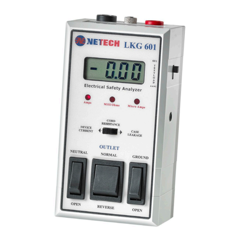
The LKG 610 is a compact Electrical Safety Analyzer designed to evaluate the electrical
safety of all electrical equipment including medical devices and physiological
Instrumentation.
The LKG 610 measures line voltage, outlet polarity, device current, earth leakage,
chassis resistance, leads leakage, case leakage, and performs lead ISO tests and point
to point measurements.
Each measurement is quickly and easily performed when its function key is pressed.
The function selected and the unit of measure is indicated by an individual LED. Either
the AAMI ESI -1993 or the IEC 601-1 test load may be selected.
Resistance measurements are made using the included model 503 single conductor
test lead. A unique feature of the LKG 610 is its ability to verify the test readings with
calibrated outputs of 200 µAmps and 1 Ohm.
The comprehensive LKG 610 provides the best combination of features, performance,
and value in a portable electrical safety analyzer.
Key Features
Fast, Accurate & Portable
Easy to Use
Large LCD Display
Accessible Line Fuse
Calibrated Test Points
15 & 20 Amp Capability
Point to Point Testing
10 Lead ECG Connector
Complies with both AAMI & IEC 601 Test Loads
LED unit of measure Indicator

LKG 610
Netech Corporation
110 Toledo St, Farmingdale, NY 11735,
http://www.NetechCorp.us
http://www.PressureMeter.com
Specifications
Display: 3-1/2 Digit LCD Display
LEAKAGE CURRENT: 0-1999 Micro Amps. All Current measurements are
made through the AAMI/ANSI ES1-1985 or IEC 601-1 test load. The meter
readings correspond to the true RMS value of the current.
Accuracy: DC to 1 KHz: 1% FS + 1 LSD
1 Khz to 100 KHz: ±2.5% FS + 1 LSD
100 KHz to 1 MHz: ±4% FS + 1 LSD
RESISTANCE: 0 TO 1999 Milli Ohms.
Accuracy: + 1 % of reading + 1 LSD
DEVICE CURRENT: 0 to 19.99 Amps
Accuracy: + 2% Full Scale + 1 LSD
Line Voltage: 1 to 300 Volts
Accuracy: +2% + 1 Volt
TEST RECEPTACLE: Hospital Grade 110 VAC -15 Amp or 220 VAC 10 Amp.
The rocker polarity switch selects NORMAL, OFF and REVERSE polarity to the
test receptacle, and a momentary Neutral switch will open the neutral line to the test
receptacle.
POWER REQUIREMENTS: 110 VAC 50-60Hz, 15 Amps or 220 VAC, 10 Amps
maximum rated for the test outlet and 0.1 Amp rated for the unit.
PHYSICAL DIMENSIONS: Size: 8.0 X 4.5 X 2.0 inches
(20.3 X 11.4 X 5.0 cm)
Weight: 2.5 lbs (1.1 kg)
ENVIRONMENTAL: Operating range: 59 to 95F (15 to 35C)
Storage Temperature: 0 to 122F (-18 to 50C)
Relative Humidity: 90% (max) at temperatures

User Manual LKG 610
10
Instrument Familiarity
2
15
1
14
12
13
11
10
9
3
4
5
6
7
8

LKG 610
Netech Corporation
110 Toledo St, Farmingdale, NY 11735,
http://www.NetechCorp.us
http://www.PressureMeter.com
Controls & Indicators
Item Name Description
1
ECG
Connectors
Universal connectors to connect ECG snaps or various sized posts
2
Display
A 3.5 digit LCD presents the result of the selected test measurement
3
Load Selector
Switch
A slide switch on the right side of the instrument to select either the
AAMI or the IEC 601-1 test load.
4 Test Jacks Calibrated outputs are provided for resistance (1 Ohm) and leakage
current (200 µA)
5 Chassis Input Connection for the 503 test cable
6 Ground
Switch
A switch to momentarily open the ground connection to the test
receptacle
7 Polarity
Switch
A three-position switch to select the normal and reverse polarity of
the test receptacle. The center position shuts the power off to the test
receptacle.
8
Neutral
Switch
A switch to momentarily open the neutral line to the test receptacle.
9 Fuse
20 Ampere fuse for 110 VAC model, 10 Ampere fuse for 230 VAC
model
10 Serial Port Optional RS 232 Serial Port
11
Zero
Adjustment
Recessed adjustment to zero any test cable resistance variations
12
Test
Receptacle
A 20 AMP power receptacle for the Device Under Test
13 Power Cord The power cord supplies power to the analyzer and to the Device
Under Test
14 Keypad Twelve push button function keys to select the test measurement
15 LEDs An LED in the corner of each function key indicates the selected
test mode and the unit of measurement displayed

User Manual LKG 610
12
Preparation for Use
The LKG 610 includes a test lead, part # 503, for measuring Cord Resistance and Case
Leakage. Connect the LKG 610 to a 110 VAC outlet (or 220 VAC outlets for the 220
Volt Model).
During the initial setup the last digit of the LCD will change gradually due to the time
constant of the RMS to DC converter. The display will stabilize to zero in a few
seconds.
There are 2 models of LKG 610 available. Prior to using the device identify the Part
number and the model purchased.
The following are the part numbers and the operational voltages.
1. PN: 535-110, for 110 Volt devices only.
2. PN: 535-220, for 220 Volt devices only.
Before proceeding with any measurement become familiar with the measurements and
the function selector switch.
CAUTION
Make sure that the power requirements of the Device Under Test are within the
power ratings of the LKG 610, 15 amps at 110 volts and 10 amps at 230 volts.
Do not leave the Device Under Test continuously turned on and connected to the
LKG601.
Before testing 220 Volt devices make sure the LKG 610 is plugged to a 220 Volt
out let using the adapter and connect the 220 Volt device to the LKG 610 using
the universal adapter supplied
Do not attempt to open the LKG 610. There are no user serviceable parts inside.
Further, the warranty will be void if the unit is opened by anybody other than
Netech trained personnel.

LKG 610
Netech Corporation
110 Toledo St, Farmingdale, NY 11735,
http://www.NetechCorp.us
http://www.PressureMeter.com
Operating Instructions
1. Line Voltage Measurement:
The default measurement setting is line voltage (LINE VOLT). When the LKG 610 is
plugged into an AC outlet, the LCD will display the measured line voltage in Volts. If the
outlet polarity is reversed the display will indicate ‘- POL’ and line voltage will not be
displayed.
2. Device Current Measurement:
Plug the Device Under Test (DUT) into the test receptacle. Set the polarity switch to
normal. Press the “DEVICE CUR” key. Turn the Device Under Test (DUT) On. The
display will present the Device Current in Amps.
3. Earth Leakage Current Measurement:
Press the “EARTH LKG” key. See Figure 2. The Earth Leakage (Ground Leakage)
Current is measured through the ground conductor of the Device Under Test. This is
only applicable to devices with a three-conductor power cord. The leakage
measurement is made internally when the CHS GND switch is momentarily pushed to
the LIFT GRND position. The display will present the measurement in µAmps. No other
connection is required.
Both Earth and Case Leakage Current measurements should be made in all power
switch combinations: the Polarity Switch in Normal, Reverse, and off; and with the
Neutral Switch Open and Closed.
Caution
When switching from Normal to Reverse or vice versa, make sure to pause the
rocker switch in the OFF position (middle). Power to the outlet will be OFF in the
open neutral position.

User Manual LKG 610
14
4. Chassis Resistance Measurement:
See Figure 2. Set the Polarity Switch to the OFF (center) position. Press the key
marked “CHS RES”. Plug the DUT into the test receptacle. Using the 503 test lead,
connect the chassis of the DUT to the CHASSIS jack on the LKG 610. The display will
present the Cord Resistance in milliohms.
Hammer pressure levels in excess of 20 PSI will cause damage t
Figure 2
Block Diagram for Cord Resistance measurement and
Case Leakage measurement (external)
5. Leads Leakage Measurement:
Leakage current of ECG leads may be measured individually or combined. To measure
the leakage press the appropriate function key LA, RA, RL, LEADS ALL, LL, or V1-V6.
The display will present the selected test measurement result in µAmps.
Device Under
Test
DUT Power Cord
Test
Lead
(503)
to
Chassis

LKG 610
Netech Corporation
110 Toledo St, Farmingdale, NY 11735,
http://www.NetechCorp.us
http://www.PressureMeter.com
6. Leads Isolation Test:
Plug the ECG device into the LKG 610. Connect the ECG leads. Press the “ISO TEST”
key. The isolation leakage will be presented on the display in µAmps.
After 30 seconds the LED will begin flashing to indicate that the applied isolation voltage
has been removed. The previous leakage measurement will be displayed. To perform
another ISO test press the “ISO TEST” key again.
WARNING:
Since the test method injects potentially hazardous current levels into the ECG
and related power system, do not conduct tests in an occupied patient location or
while the patient is connected to a related power system branch.
CAUTION
During Isolation leakage measurements the LKG 610 introduces line voltage into
the patient leads. Even though it is current limited to 1milliAmp, it is potentially
lethal.
7. Case Leakage Current:
The Case Leakage Current is measured through the test lead cable. Connect the test
Lead to the case of the DUT(Device under test). The leakage measurement is made
when the CHS GND switch is momentarily switched to the LIFT GRND position. The
display will present the measurement in Micro Amps. No other connection is required.
To measure the Case Leakage of devices with plastic enclosures, wrap aluminum foil
around the case of the DUT and connect the test lead to the foil.
8. Point To Point Testing:
Use two 503 test leads plugged into the “REF GND” and “CHASSIS” EXTERNAL
INPUT jacks. Push the CASE LKG key. The display will present the measurement in
microAmps.
Note: “OL” displayed in any measurement function indicates an over range
condition.

User Manual LKG 610
16
Performance Check
The following tests will confirm that the LKG 610 is performing properly.
1. Connect the LKG 610 to a 110 VAC outlet (220 VAC for the LKG 610-220).
The power on default function is “Line Volt”. The LCD display will present the
line voltage in Volts. If the outlet polarity is reversed the LCD will indicate ‘-
POL’.
2. The Test Lead resistance is offset internally and adjusted at the factory. The
Test Lead resistance can be checked by connecting the Test Lead between
the receptacle ground and the case ground (CHASSIS). When the CHS GND
switch is momentarily pressed, the connection will be open and the display
will read zero.
A test lead other than the 503 may require adjustment with the zero adjustment
control.
3. Connect the Test Lead to the REF GND jack. Press the switch “CHS RES”.
The display will read 1000 milliOhms + 5% (1 Ohm).
4. Connect the Test Lead to the TEST POINTS marked 200 µA. Press the
“EARTH LKG” key. The display will read 200 µA + 2%.
Theory of Operation
The LKG 610 circuitry can be divided into main functional blocks as shown in Figure 3.
Each performs a key role in the operation of the instrument.
Figure 3
Functional block diagram of the LKG 610
DSP & Function
Selector
AAMI or
IEC 601
RMS TO
DC
CURRENT
SOURCE
LEDS
DISPLAY
AMP
TEST
RECEPTACLE
E
C
G

LKG 610
Netech Corporation
110 Toledo St, Farmingdale, NY 11735,
http://www.NetechCorp.us
http://www.PressureMeter.com
Block Diagram Description
Test Load: The input test load is user selectable to AAMI ESI –1993 or to IEC 601.
RMS Converter and Amplifier: The input amplifier buffers the input. The RMS
converter generates a DC voltage equal to the RMS value at its input. The gain
Amplifier sets the gain for the measurements. When the MODE switch selects leakage
current measurement, the AAMI LOAD is connected in front of the INPUT AMPLIFIER,
and the voltage developed across it from the leakage current is measured.
Current Source and Amplifier: Resistance is measured by connecting the
current source to the resistance to be measured and measuring the voltage with the
input amplifier.
Test Receptacle: This supplies power to the unit under test, 110 VAC rated at 15
Amps (220 VAC). The rocker polarity switch selects NORMAL, OFF and REVERSES
polarity in the test receptacle.
Display: All measurements are displayed on a 3-1/2 digit LED display. Over range
is indicated by showing a 1 in the most significant digit

User Manual LKG 610
18
Maintenance and Storage
Maintenance
The LKG 610 requires minimum maintenance.
Periodically check the inlet plug, outlet receptacle, and wiring for any damage, wear,
cracks, cuts, or other defects. Also check the case for any damage or cracks.
In order to ensure accuracy, the LKG 610 should be checked periodically. A calibrated
output is provided at the TEST JACK for both Case Leakage and Cord Resistance
functions.
When making a resistance measurement with a Test Cable other than the one supplied
with the LKG 610, the user can zero the leads with the zero adjustment potentiometer.
This will not affect the internal calibration of the unit.
Annual calibration is recommended. If the LKG 610 is returned to Netech for
recalibration before the first year warranty expires, Netech will provide a second year
warranty. The warranty is void if the LKG 610 is serviced by anyone other than Netech
or if the warranty seal is broken.
Calibration / Service
The mechanical assembly of LKG 610 contains no parts that can be serviced by the
user. The unit should be returned to Netech Corporation for repair or calibration. The
alignment and adjustment parameters are critical to the robust and efficient
performance of the unit and can be performed only at the factory.
The unit is factory calibrated with NIST traceable standards and recommended to be
calibrated once a year.
Netech maintains a complete repair and recalibration service at a very low cost and fast
turnaround. Estimates for repair and recalibration are available upon request.
LKG 610 contains NO USER SERVICEABLE PARTS and calibration/ service
should be performed only by Netech. Attempt to repair / service the unit outside
Netech voids the warranty.

LKG 610
Netech Corporation
110 Toledo St, Farmingdale, NY 11735,
http://www.NetechCorp.us
http://www.PressureMeter.com
Returning the LKG 610 for Re-Calibration
Products returned to Netech for repair or recalibration requires a RMA (Return
Authorization Number) for speedy processing of the service required.
To obtain a RMA number follow the link http://www.NetechCorp.us and fill in the required
information, Email service@netechcorp.us or call 800-547-6557 (US & Canada),
International 631-531-0100.
When shipping units to the factory enclose a copy of the RMA and the number should
be on used as the reference in the shipping label.
The shipment should be addressed to:-
Attn: Service Department
Netech Corporation
110 Toledo St.
Farmingdale, New York 11735.

User Manual LKG 610
20
Appendix
This section is intentionally left blank for future use
Other manuals for LKG 610
1
Table of contents
Other Netech Measuring Instrument manuals
Netech
Netech EXPMT 2000 User manual

Netech
Netech LKG 601 User manual
Netech
Netech MultiPro 2000 User manual
Netech
Netech DigiMano 2500 Series User manual
Netech
Netech DigiMano 2000 User manual
Netech
Netech UPM 2000 User manual
Netech
Netech EXPMT 2000 User manual
Netech
Netech MT-100 User manual
Netech
Netech LKG 610 User manual
Netech
Netech DigiFlow 2000 User manual

