EGO AMS1000 User manual

WARNING: To reduce the risk of injury, the user must read and understand the Operator’s Manual before
using this product. Save these instructions for future reference.
OPERATOR’S MANUAL
SUN SHADE
MODEL NUMBER AMS1000
Español p. 25
Français p. 13
THIS SUN SHADE IS EXCLUSIVELY
COMPATIBLE WITH EGO POWER+
ELECTRIC ZERO TURN MOWER
ZT4200L/ZT4200L-FC/ZT5200L/ZT5200L-FC.

SUN SHADE — AMS10002
TABLE OF CONTENTS
Packing List ................................................................................3-4
Assembly & Installation .......................................................................5-8
Operation ....................................................................................9
Warranty ................................................................................10-11

3SUN SHADE — AMS1000
PACKING LIST
PART NAME FIGURE QUANTITY
Vinyl Canopy 1
Main Beam 1
Supporting Beam 2
Higher Supporting Rod 1
Lower Supporting Rod 1
Supporting Tube 1
Stand Tube 2

SUN SHADE — AMS10004
Post 2
Crossbar 2
Hex Flange Bolt Aand Flange
Nut Set
M8*45
2
Hex Flange Bolt Band Flange
Nut Set
M8*70
4
Hex Flange Bolt C and Flange
Nut Set
M8*75
4
Carriage Bolt and Flange Nut Set
M8*50
4
Tools Needed (Not Included)
◾1/2 in (13mm) wrench
◾Impact wrench with a 1/2 in (13 mm) socket (recommended to get the job done faster).
ASSEMBLY & INSTALLATION
WARNING: If any part is damaged or missing, do not assemble this product until the part is replaced. Use of
this product with damaged or missing parts could result in serious personal injury.
WARNING: Do not attempt to modify this product or create accessories not recommended. Any such alteration
or modification is misuse and could result in a hazardous condition leading to serious personal injury.

5SUN SHADE — AMS1000
WARNING: Before assembly or installation, place the Zero Turn Mower on a rm and level surface and set the
parking brake. Stop the motors and remove the safety key to prevent unintended starting.
UNPACKING
◾This product requires assembly and installation on the Zero Turn Mower.
◾Carefully remove all parts from the box. Make sure that all parts in packing list are included.
◾Inspect the parts carefully to make sure that no breakage or damage occurred during shipping.
◾Do not discard the packing material until you have carefully inspected and satisfactorily operated the product.
◾If any part is damaged or missing, please return the product to the place of purchase.
NOTE: Left and Right position are determined from the operator’s position while seated on the mower.
1. Park the mower on a level surface and set the parking brake.
2. Stop the motors and remove the safety key.
3. Remove the two attachment mounting covers from the mower to expose two mounting holes (Fig. 1). Place the
attachment mounting covers in the storage compartment of your mower.
4. Insert the posts into the mounting holes of the mower as shown in Fig. 2.
1
Attachment Mounting Covers
Attachment
Mounting
Cover Storage
2
Mounting Hole
Post

SUN SHADE — AMS10006
5. Hold the crossbar between the posts to align the two
mounting holes on both ends of the crossbar with the
two lower mounting holes of each post. Insert four
hex flange bolts Band flange nuts on both sides and
finger-tighten the bolts and nuts (Fig. 3).
6. Securely tighten all four bolts on both sides by two
wrenches (not included).
7. Lift the left stand tube marked with “L” to align the
two bottom holes in the stand tube with the holes in
the left post on the mower as shown in Fig. 4.
8. Use two hex flange bolts Cand flange nuts to secure
the stand tube to the post using two wrenches (not
included) (Fig.4).
9. Attach the right stand tube marked with “R” in the
same way to the right post.
3
Post
Crossbar
4
Post
“L” Mark
Stand Tube

7SUN SHADE — AMS1000
10.Place the main beam on a flat surface. Pass the two
legs of the higher supporting rod through the two holes
close to the front end of the main beam, the legs of the
lower supporting rod through the two holes far from the
front end of the main beam as shown in Fig. 5
11.Insert the top of the supporting beam into the either
tube of the main beam, then insert another supporting
beam into the main beam, align the two holes in the
main beam with the holes in the supporting beam,
use two Carriage bolts and flange nuts to secure the
supporting beam to the main beam (Fig. 6).
12.Insert the two bottom ends of the supporting frame
into the stand tubes on the mower as shown in Fig. 7,
align the holes in the supporting frame with one of
the four square holes in the stand tubes – this will
determine sun shade height (Fig. 7).
13.Use the two carriage bolts and flange nuts to
attach the supporting frame to the stand tubes with
the impact wrench (not included). Do not tighten
completely.
14.Align the two holes in the supporting tube with the
holes in the supporting frame as shown in Fig. 8. Use
two hex flange bolts Aand flange nuts to secure the
supporting tube to the supporting frame using two
wrenches (not included).
15.Securely tighten the two bolts and nuts shown in
Fig. 7 with the impact wrench (not included).
5
Front End
Leg
Higher Supporting Rod
Lower Supporting Rod
Main Beam
1
1
2
2
7
Supporting Frame
Stand Tube
Four Square
Holes
8
Supporting Frame
Supporting Tube
1
1
2
2
6
Main Beam
Supporting Beam

SUN SHADE — AMS10008
16.Place the vinyl canopy on top of the supporting frame, first fitting the back of the vinyl canopy around the curved
tubes of the frame, then fitting the front of the vinyl canopy around the front end of the frame. Make sure the mesh
screen of the vinyl canopy is on the outside of the supporting tube. Secure the mesh screen to the supporting frame
and supporting tube in place using six hook and loop fasteners of the mesh (Fig. 9).
CAUTION: Make sure the mower seat can slide freely after attaching the sun shade.
9
Vinyl Canopy
Hook and Loop
Mesh Screen
Supporting Frame
Supporting Tube
Curved Tube
Front End

9SUN SHADE — AMS1000
OPERATION
Read the operator’s manual and safety rules before operating your mower with the sun shade attached.
CAUTION: This sun shade does not provide protection against collision, rollover or other accidents.
CAUTION: Watch out for low tree limbs and other overhead objects which may interfere with the sun shade.
CAUTION: Never transport the mower in an open truck or open trailer while the sun shade is attached.
Check the area of the operation thoroughly before using the mower with the sun shade attached. The added height of the
sun shade and a reduced field of vision require extra caution during operation.
Remove the upper sun shade frame and canopy before transporting the mower in an open truck or open trailer.

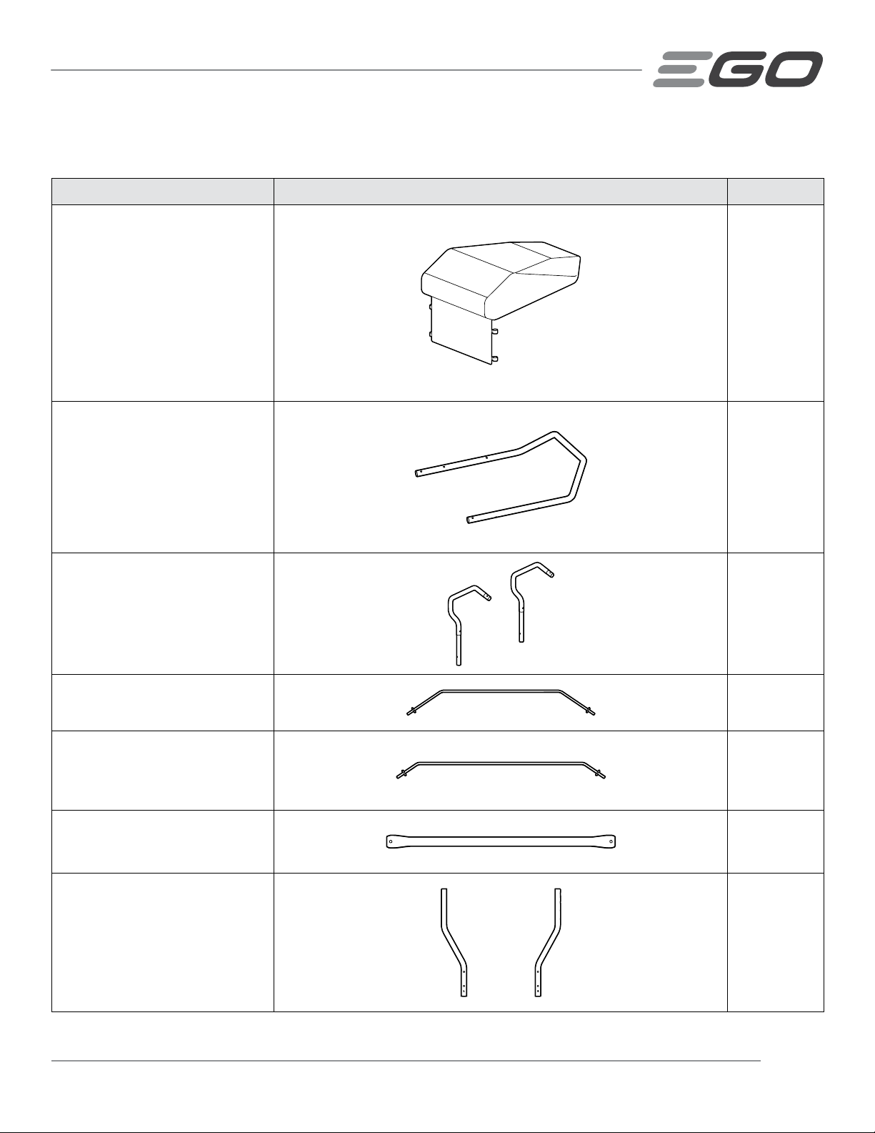
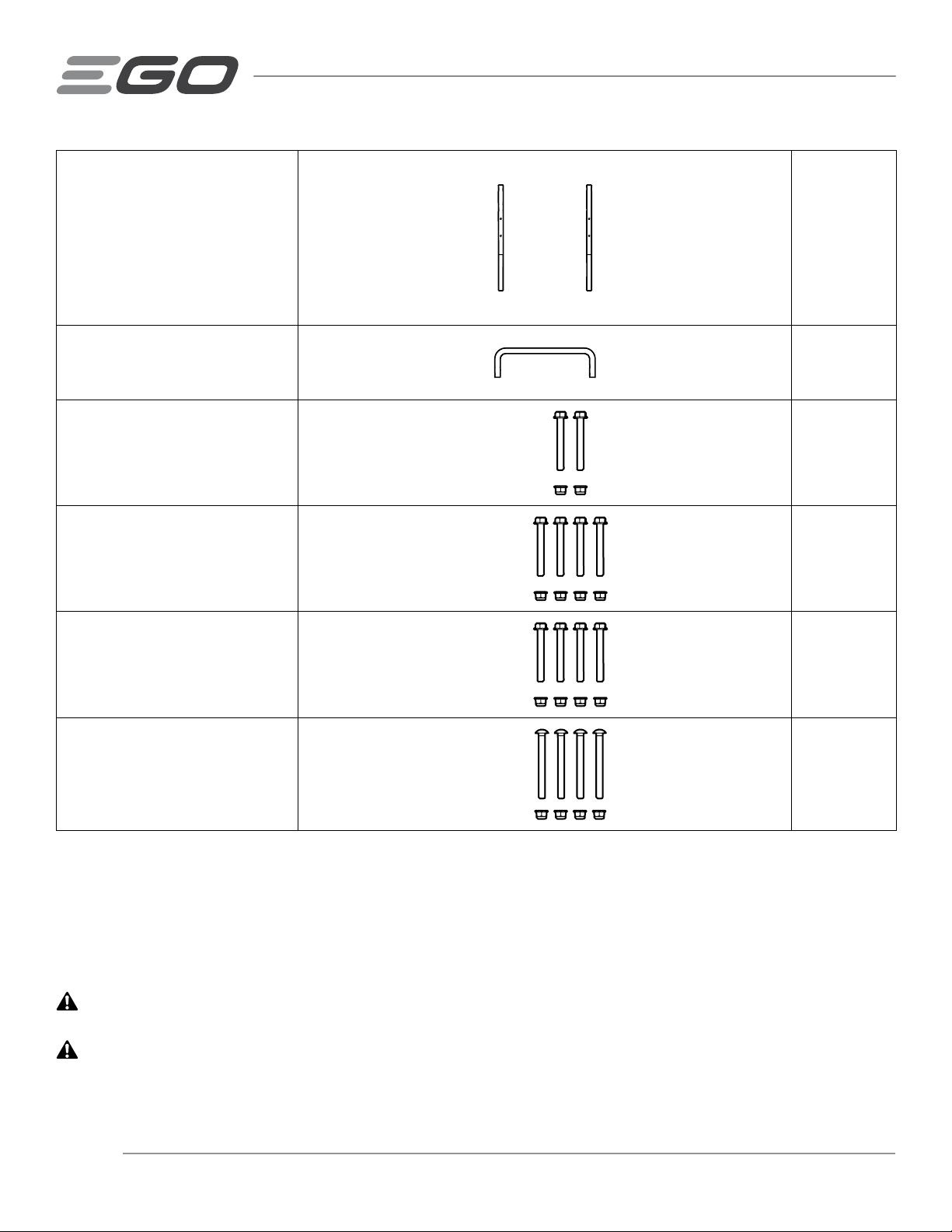
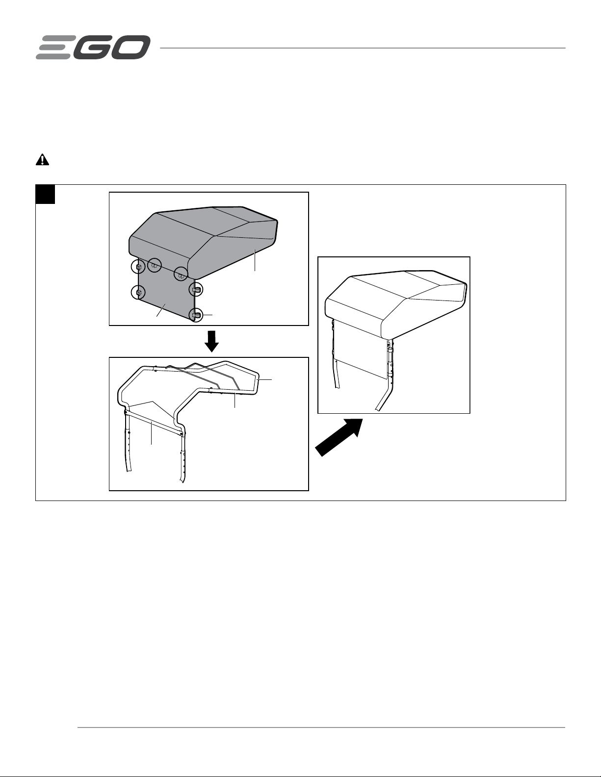
SUN SHADE — AMS100010
WARRANTY
EGO WARRANTY POLICY
5-year limited warranty on EGO POWER+ outdoor power equipment and portable power for personal, household use.
3-year limited warranty on EGO POWER+ System battery packs and chargers for personal, household use. An additional
2-year extended warranty applies for the 10.0Ah/12.0Ah battery whether sold separately (Model# BA5600T/BA6720T)
or included with any tool, if it is registered within 90 days of purchase. 5-year limited warranty on CHV1600 charger,
designed for use with Zero Turn Riding Mower for personal, household use.
2 year/1year limited warranty on EGO outdoor power equipment, portable power, battery packs, and chargers for
professional and commercial use.
The detailed warranty periods by products can be found online at
http://egopowerplus.com/warranty-policy.
Please contact EGO Customer Service Toll-Free at 877-346-9876 (877-EGO-ZTRM) any time you have questions or
warranty claims.
LIMITED SERVICE WARRANTY
EGO products are warranted against defects in material or workmanship from the date of original retail purchase for the
applicable warranty period. Defective product will receive free repair.
a) This warranty applies only to the original purchaser from an authorized EGO retailer and may not be transferred.
Authorized EGO retailers are identified online at http://egopowerplus.com/warranty-policy.
b) The warranty period for reconditioned or factory certified products used for residential purpose is 1 year, for
industrial, professional or commercial purpose is 90 days.
c) The warranty period for routine maintenance parts, such as, but not limited to, ride-on mower seat, wheels,
tires, anti-scalp wheels, brake disc, friction block, blades, trimmer heads, chain bars, saw chains, belts, scraper
bars, rubber paddles, augers, skid shoes, blower nozzles, and all other EGO accessories is 90 days for residential
purpose, 30 days for industrial, professional or commercial purpose. These parts are covered for 90/30 days from
manufacture defects in normal working conditions.
d) This warranty is void if the product has been used for rental purpose.
e) This warranty does not cover the damage resulting from modification, alteration or unauthorized repair.
f) This warranty only covers defects arising under normal usage and does not cover any malfunction, failure or defect
resulting from misuse, abuse (including overloading of the product beyond capacity and immersion in water or
other liquid), accidents, neglect or lack of proper installation, and improper maintenance or storage.
g) This warranty does not cover normal deterioration of the exterior finish, including but not limited to scratches,
dents, paint chips, or to any corrosion or discoloring by heat, abrasive and chemical cleaners.
HOW TO OBTAIN SERVICE
For warranty service, please contact EGO customer service toll-free at 877-346-9876 (877-EGO-ZTRM). When
requesting warranty service, you must present the original dated sales receipt. An authorized service center will be
selected to repair the product according to the stated warranty terms. When bringing your product to the authorized
service center, there may be a small deposit that will be required when dropping off your tool. This deposit is refundable
when the repair service is deemed to be covered under warranty.

11SUN SHADE — AMS1000
ADDITIONAL LIMITATIONS
To the extent permitted by applicable law, all implied warranties, including warranties of MERCHANTABILITY or FITNESS
FOR A PARTICULAR PURPOSE, are disclaimed. Any implied warranties, including warranties of merchantability or fitness
for a particular purpose, that cannot be disclaimed under state law are limited to the applicable warranty period defined
at the beginning of this article.
Chervon North America is not responsible for direct, indirect, incidental or consequential damages.
Some states do not allow limitations on how long an implied warranty lasts and/or do not allow the exclusion or limitation
of incidental or consequential damages, so the above limitations may not apply to you.
This warranty gives you specific legal rights, and you may also have other rights which vary from state to state.
For customer service contact us toll-free at: 877-346-9876 (877-EGO-ZTRM) or EGOPOWERPLUS.COM. EGO Customer
Service, 769 SEWARD AVE NW / Suite 102 Grand Rapids, MI 49504


AVERTISSEMENT: Afin de réduire les risques de blessure, l’utilisateur doit lire et com-
prendre le guide d’utilisation avant d’utiliser ce produit. Conservez le présent guide afin
de pouvoir le consulter ultérieurement.
MODE D’EMPLOI
PARE-SOLEIL
NUMÉRO DE MODÈLE AMS1000
CE KIT DE PARE-SOLEIL EST EXCLUSIVEMENT
COMPATIBLE AVEC LA TONDEUSE ÉLECTRIQUE
À RAYON DE BRAQUAGE ZÉRO EGO POWER+
ZT4200L/ZT4200L-FC/ZT5200L/ZT5200L-FC.

14 PARE-SOLEIL — AMS1000
TABLE DES MATIÈRES
Liste des pièces...........................................................................15-16
Montage et installation .....................................................................16-20
Fonctionnement..............................................................................21
Garantie .................................................................................22-23

15PARE-SOLEIL — AMS1000
LISTE DES PIÈCES
NOM DE LA PIÈCE FIGURE QUANTITÉ
Auvent en vinyle 1
Poutre principale 1
Poutre de support 2
Tige de support du haut 1
Tige de support du bas 1
Tube de support 1
Tube vertical 2

16 PARE-SOLEIL — AMS1000
Poteau 2
Barre transversale 2
Boulon hexagonal à bride de
fixation Aet bride de fixation
Jeu d’écrous M8*45
2
Boulon hexagonal à bride de
fixation Bet bride de fixation
Jeu d’écrous M8*70
4
Boulon hexagonal à bride de
fixation Cet bride de fixation
Jeu d’écrous M8*75
4
Jeu de boulons de carrosserie et
d’écrous à bride de fixation
M8*50
4
Outils nécessaires (non fournis)
◾Clé de 13 mm / 1/2 po
◾Clé à chocs avec une douille de 13 mm / 1/2 po (recommandée pour faire le travail plus rapidement).
MONTAGE & INSTALLATION
AVERTISSEMENT : Si certaines pièces sont endommagées ou manquantes, n’assemblez pas ce produit
avant que ces pièces aient été remplacées.L’utilisation de ce produit avec des pièces endommagées ou manquantes
pourrait causer des blessures graves.
AVERTISSEMENT : Ne tentez pas de modier ce produit ou de créer des accessoires qu’il n’est pas
recommandé d’utiliser avec lui. Une telle altération ou modification constituerait une utilisation abusive et pourrait
créer une situation dangereuse avec risque de blessures graves.

17PARE-SOLEIL — AMS1000
AVERTISSEMENT : Avant le montage ou l’installation, placez la tondeuse à rayon de braquage zéro sur une
surface ferme et plane, et serrez le frein de stationnement. Arrêtez les moteurs et retirez la clé de sécurité
pour éviter tout risque de démarrage involontaire.
DÉBALLAGE
◾Ce produit nécessite un assemblage et une installation sur la tondeuse à rayon de braquage zéro.
◾Retirez soigneusement toutes les pièces de la boîte. Assurez-vous que toutes les pièces figurant sur liste des pièces
sont incluses.
◾Inspectez attentivement les pièces pour vous assurer qu’aucun dommage ou bris de pièce(s) ne s’est produit
pendant le transport.
◾Ne jetez pas les matériaux d’emballage avant d’avoir inspecté attentivement le produit et de l’avoir mis en marche
de façon satisfaisante.
◾Si une pièce quelconque est endommagée ou manquant, rapportez le produit dans le magasin où vous l’ave acheté.
REMARQUE : Les positions gauche et droite sont déterminées à partir de la position de l’opérateur assis sur la tondeuse.
1. Garez la tondeuse sur une surface plane et activez le frein de stationnement.
2. Arrêtez les moteurs et retirez la clé de sécurité.
3. Retirez les deux caches de montage des attachements de la tondeuse pour exposer deux trous de montage (Fig. 1).
Placez les caches de montage des attachements dans le compartiment de rangement de votre tondeuse.
4. Insérez les poteaux dans les trous de montage de la tondeuse comme illustré à la Fig. 2.
1
Rangement
des caches de
montage des
attachements
Caches de montage des
attachements
2
Trou de montage
Poteau

18 PARE-SOLEIL — AMS1000
5. Tenez la barre transversale entre les poteaux pour
aligner les deux trous de montage des deux extrémités
de la barre transversale sur les deux trous de montage
du bas de chaque poteau. Insérez quatre boulons
hexagonaux à bride de fixation Bet des écrous à bride
de fixation des deux côtés, et serrez les boulons et les
écrous à la main (Fig. 3).
6. Serrez fermement les quatre boulons des deux côtés à
l’aide de deux clés (non fournies).
7. Soulevez le tube vertical gauche marqué par un « L»
pour aligner les deux trous inférieurs du tube vertical
sur les trous du poteau gauche de la tondeuse, comme
illustré à la Fig. 4.
8. Utilisez deux boulons hexagonaux à bride de fixation
Cet des écrous à bride de fixation pour fixer le tube
vertical au poteau à l’aide de deux clés (non fournies)
(Fig.4).
9. Fixez de la même manière le tube vertical droit marqué
par un « R» au poteau droit.
3
Poteau
Barre
transversale
4
Poteau
Repère « L »
Tube vertical

19PARE-SOLEIL — AMS1000
10.Placez la poutre principale sur une surface plane.
Insérez les deux pieds de la tige de support du haut
dans les deux trous proches de l’extrémité avant de la
poutre principale, et les pieds de la tige de support du
bas dans les deux trous éloignés de l’extrémité avant
de la poutre principale, comme illustré à la Figure 5
11.Insérez le haut de la poutre de support dans l’un
quelconque des tubes de la poutre principale, puis
insérez une autre poutre de support dans la poutre
principale, alignez les deux trous de la poutre
principale sur les trous de la poutre de support, et
utilisez deux Jeu de boulons de carrosserie et d’écrous
à bride de fixation et des écrous à bride de fixation
pour fixer la poutre de support à la poutre principale
(Fig. 6).
12.Insérez les deux extrémités inférieures du cadre de
support dans les tubes verticaux de la tondeuse comme
illustré à la Fig. 7, et alignez les trous du cadre de support
sur l’un des quatre trous carrés des tubes verticaux –
ceci déterminera la hauteur du pare-soleil (Fig. 7).
13.Utilisez les deux boulons de carrosserie et les écrous
à bride de fixation pour fixer le cadre de support aux
tubes verticaux à l’aide de la clé à chocs (non fournie).
Ne serrez pas complètement.
14.Alignez les deux trous du tube de support sur les trous
du cadre de support, comme illustré à la Fig. 8. Utilisez
deux boulons hexagonaux à bride de fixation A et des
écrous à bride de fixation pour fixer le tube de support
au cadre de support à l’aide de deux clés (non fournies).
5
Extrémité
avant
Pied
Tige de support du haut
Tige de support du bas
Poutre principale
1
1
2
2
6
Poutre
principale
Poutre de support
1
1
2
2
7
Cadre de support
Tube vertical
Quatre
trous carrés
8
Cadre de support
Tube de support

20 PARE-SOLEIL — AMS1000
15.Serrez fermement les deux boulons et les écrous indiqués à la Fig. 7 à l’aide de la clé à chocs (non fournie).
16.Placez l’auvent en vinyle sur le cadre de support, en ajustant d’abord l’arrière de l’auvent en vinyle autour des tubes
incurvés du cadre, puis en ajustant l’avant de l’auvent en vinyle autour de l’extrémité avant du cadre. Assurez-vous
que la grille en mailles de l’auvent en vinyle se trouve à l’extérieur du tube de support. Fixez la grille en mailles au
cadre de support et au tube de support pour la mettre en place à l’aide de six attaches auto-agrippantes pour la
grille (Fig. 9).
MISE EN GARDE : Assurez-vous que le siège de la tondeuse peut glisser librement après avoir fixé le pare-soleil.
9
Auvent en vinyle
Fermeture auto-agrippante
Écran à mailles
Cadre de support
Tube de support
Tube incurvé
Extrémité
avant
Table of contents
Languages:
Other EGO Garden Machinery Accessories manuals