Ehrgeiz Fusion 2 User manual

USER MANUAL
CONTENTS USER MANUAL
Manual for Software Version 1010 released on 09/29/2018
This version of the Manual is released on 10/19/2018
Introduction .........................................................1
Safety Instructions.............................................1
Delivery Contents ..............................................3
Fixture Dimensions............................................3
Installations..........................................................4
Structural Connection........................................4
Horizontal Installation on the floor.....................4
Horizontal hanging with tilt bracket....................5
Horizontal hanging with Omega Bracket.............5
Safety attachment..............................................5
Hanging vertically “dropped”.............................5
Vertical Installation on the floor .........................5
Connections .........................................................6
Mains & DMX ....................................................6
DMX..................................................................7
Wireless DMX....................................................7
Operations ...........................................................8
Menu control ....................................................8
Menu map........................................................9
Software updates............................................12
IR Control........................................................13
Program Mode................................................13
DMX Modes ....................................................14
Standard .....................................................15
Advanced.....................................................15
Pattern ........................................................16
RGBW..........................................................16
Compressed ................................................17
Pixel ............................................................17
Pixel RGBW..................................................18
Pixel Dim .....................................................18
Services..............................................................19
Trouble Shooting.............................................19
Maintenance...................................................19
Appendix...............................................................I
Specifications.....................................................I
Exploded drawing.............................................II
Exploded drawing accessory.............................III
Spareparts.......................................................IV
Colourwheel channel chart................................V
Control channel chart.......................................VI
Shutter channel chart.......................................VI
Pattern channel chart......................................VII
Static Patterns..............................................VII
Animated Patterns ......................................VIII
Dimmer Curves................................................. X

Introduction →Safety Instructions
1
Introduction
Thank you for your purchase and usage of the Ehrgeiz Fusion 2.
You have chosen a reliable product with outstanding features. The device is easy to use and is made of high quality components.
Every Ehrgeiz Product is checked before shipping to secure you are able to receive a great product without compromise. This is not a
toy. Our ambitious aim is to get you a reliable working tool.
Safety Instructions
In General
In order to maintain the condition and to ensure a safe operation, it is important for all users to follow the safety instructions and
warning notes written in this manual.
Do not operate the fixture with missing or damaged covers, shields or any optical component.
Please consider that unauthorized modifications to the device are forbidden due to safety reasons.
If the device is operated in any way that’s not described in this manual, the product may suffer damage and the guarantee will
become void. Furthermore, misuse may lead to dangers like short-circuit, burns, electric shock, burns due to ultraviolet radiation,
lamp explosion, crash, etc.
IP65 protection rating
The fixture is dust tight (first digit 6) and protected against water jets by a nozzle against enclosure from any direction (second digit
5).
Prevention from electrical shock
Make sure to ground (earth) the fixture electrically. (It’s essential to connect the yellow/green conductor to earth)
Main Connection
Do not apply any AC mains power to the fixture at any other voltage than that specified.
Rigging
Check that all external covers and rigging hardware are securely fastened.
When choosing the installation-location, please make sure that the fixture is not exposed to extreme heat. There should not be any
cables lying around. You endanger your own and the safety of others.
Make sure that the area below the installation place is cordoned off when rigging, de-rigging or servicing the fixture.
If suspending from a rigging structure, fasten the fixture to a rigging clamp with M10 bolts screwed into the threaded hole in the
center of the brackets of the fixture.
Make sure all fixtures are operated and installed by qualified personnel with the relevant national certifications.
Install, as described in this manual, a secondary attachment such as a safety wire that is approved by an official body.

Introduction →Safety Instructions
2
Positioning:
The fixture must be positioned at least 0.2m minimum distance to illuminate objects.
Keep all inflammable materials at least 0.2m from this fixture.
Allow to place the fixture on an inflammable surface.
The maximum ambient temperature of 40°C may not be exceeded.
The exterior of this fixture can reach a very high temperature during operation. Avoid contact by persons and materials.
Maintenance:
This fixture is for professional use only. It is not for household use.
Always unplug the mains for any maintenance.
Risk of eye injury:
Do not stare directly into the light when it is switched on. Do not look at LEDs with magnifying glasses, telescopes, binoculars, or
similar optical instruments that may concentrate the light output.

Introduction →Delivery Contents
3
Delivery Contents
You received your Fusion 2 with the following content
•Fusion 2 20x15W Osram LED Bar with 6° beam angle
•powerCON TRUE1® Input cable Input cable with Neutrik TRUE1 and Schuko plug
•Glare Shield Shield to avoid looking directly into the fixture from the side
•Tilt Brackets with fast locks Brackets with stepless manual Tilt adjustment
•Quick Release Pins Bolts to structuraly connect 2 devices
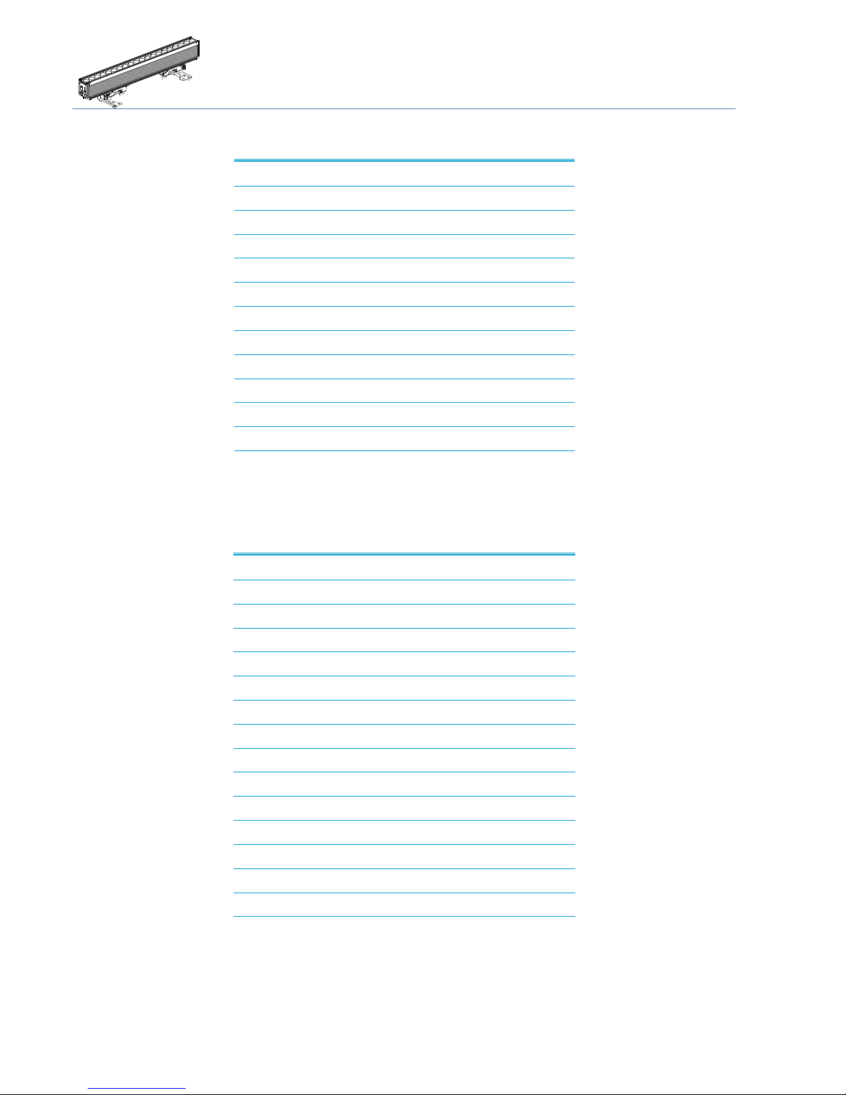
Fixture Dimensions
Dimensions in mm
90
170
125
222
1006
131
232
1019
Installations →Structural Connection
4
Installations
Your Fusion 2 can be installed in every kind of following positions. Please see the explanations and rely to the instructions for a safe
operation and secure handling.
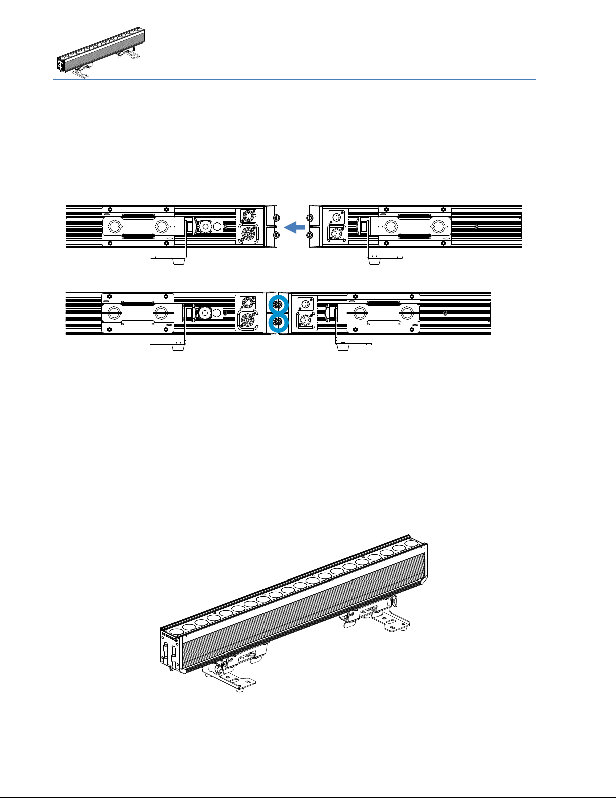
Structural Connection
The Fusion 2 can be connected using the included quick-release pins. Place the devices next to each other.
Insert both Pins to connect the devices.
For the first uses this may be a little hard. Move the devices a little until the Bolts can be inserted completely.
For vertical installation do not exceed the amount of 3pieces. (caution, provisional specification) In case of hanging installation,
each device needs to be saved individually!
Using the quick-release pins for horizontal installation is not recommended. Each device should individually be installed with the
given installation options below.
Horizontal Installation on the floor
You could place the Fusion 2 on the floor. Please make sure the surface is plane and the reliability of the floor is sufficient.

Installations →Horizontal hanging with tilt bracket
5
Horizontal hanging with tilt bracket
You can attach the Fusion 2 to a Truss or Pipe. Notice that the tilt bracket should face down from the hanging structure.
Use the centered holes in the Tilt Bracket
Horizontal hanging with Omega Bracket
You can use the additional fix Omega Brackets (optional accessory) to hang the device horizontal
Safety attachment
In any case of rigging the device attach the Safety rope to any of the dedicated eyelets integrated into the sliding brackets.
Hanging vertically “dropped”
Use the vertical Adapter set (including Omega Bracket, optional accessory) to “drop” the Fusion from a rigging structure.
Notice that we will release a detailed rigging manual for the different options shortly.
Vertical Installation on the floor
Use the vertical Adapter (optional accessory) in combination with a base plate (optional accessory).
Use the Small standing plate (optional accessory) if you only wish to install one Fusion 2.
If you want to install more than one device, screw the Small standing plate to a normal truss base plate.
Notice that we will release a detailed rigging manual for the different options shortly.

Connections →Mains & DMX
6
Connections
Mains & DMX
Fusion 2 offers standard powerCON TRUE1 as well as fully IP65 rated 5 pin XLR connectors for the Mains and DMX connection.
Please only use high quality cables fitting the local regulations and connection standards.
We only recommend the usage of H07 RN-F 3G2.5 on Original Neutrik powerCON TRUE1 for mains connection and digital 110 Ohm
DMX cable with original Neutrik 5 pin XLR HD.
The internal power wiring is done with a cable cross section of 2.5mm².
output
input

Connections →DMX
7
DMX
We recommend the use of High quality XLR connectors like original NEUTRIK HD. Please use professional digital DMX cable with a
surge impedance of 110 Ω.
Please notice that the USITT DMX Standard does allow to use a max of 32 DMX fixtures in one line. You should terminate the signal
by a 120 Ω resistor.
In the Standard mode the Fusion 2 uses 12 DMX channels.
Connect the devices and increase the value of the DMX channel by 12 from one device to another
Wireless DMX
The device can be equipped with a Wireless DMX Receiver from Wireless Solution Made in Sweden (W-DMX ™).
Please contact your Ehrgeiz distributor for detailed information of the necessary hardware & software update.
When the W-DMX receiver is installed, enable it with the option in the service Menu (only needs to be done once and does not set
back when you set the device to “factory default”
To establish a connection, enable the W-DMX Option and simply use the “Link” Option in the Fusion 2 Menu. After that, set your
transmitter to Link Mode.
After both devices are linked you will be able to control the device via Wireless DMX, as long as the W-DMX Mode is turned on in the
Menu.

Operations →Menu control
8
Operations
Menu control
Your Fusion 2 has an easy to read and setup OLED display and Menu. It is programmed with a lot of built in functions as well as
DMX Modes for different applications. Please notice that the display will flip automatically while you turn the fixture (Can be
disabled in the menu).
The Menu of the Fusion 2 is mainly intuitive. You will find a menu map on the following pages. The four buttons are used to scroll
the values, select a setting or hop back in the menu structure:
Menu Go back in the menu structure or leave a value as it is
Enter Go forward in the menu structure or confirm the selected value
UP/DOWN Scroll up / down in the menu structure or scroll the selected value
display
Input buttons

Operations →Menu map
9
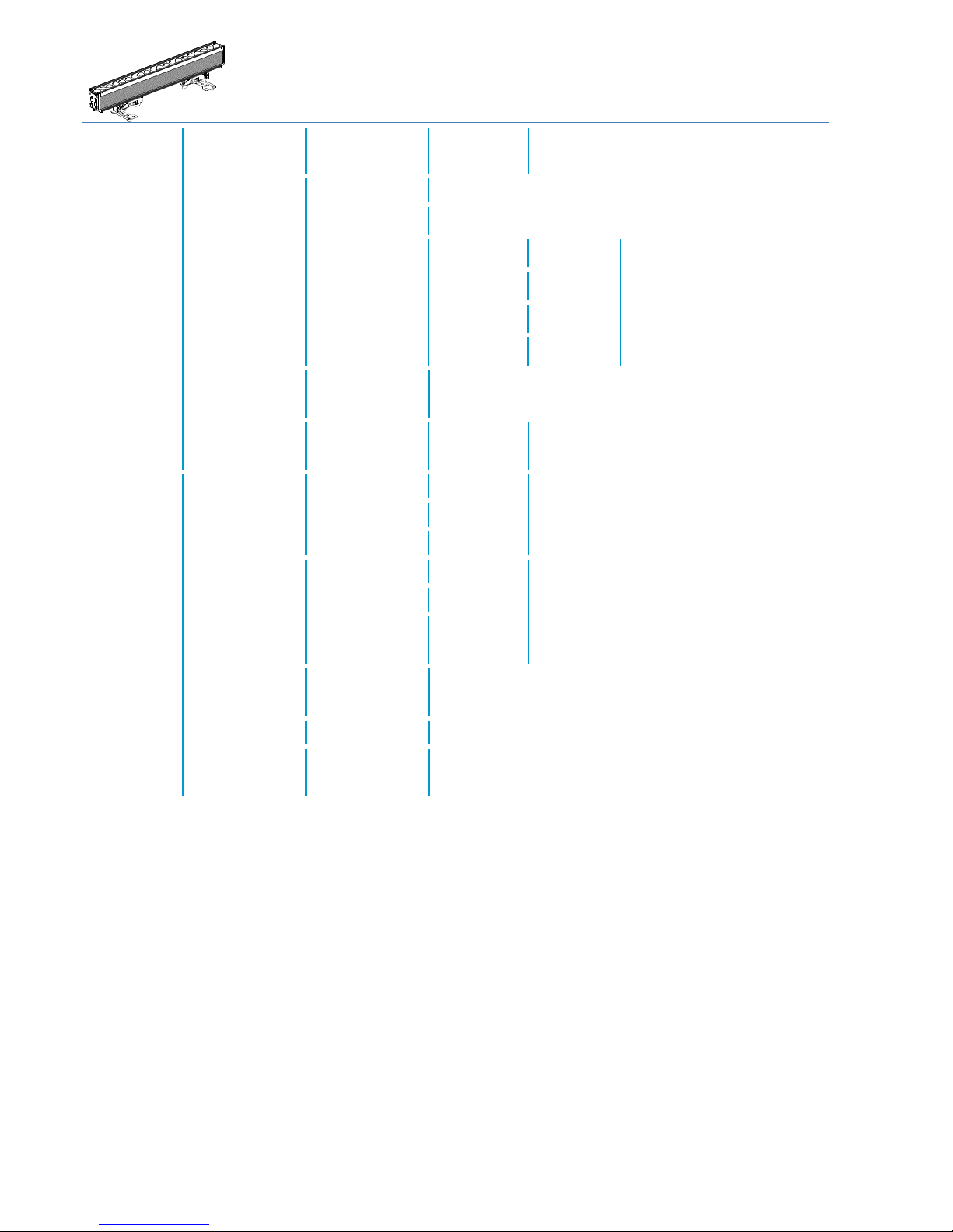
Menu map
DMX
Adress
1-XXX
Set the DMX Adress
Mode
Standard - 12
Advanced - 17
Pattern - 27
RGBW - 4
compressed - 6
Pixel –92
Pixel RGBW - 80
Pixel Dim - 32
Set the desired DMX Mode.
For detailed information see DMX Modes on page 13.
RDM
On* / Off
Enable / disable the RDM function
Reset via DMX
On* / Off
Choose whether a device reset can be done via DMX signal
No DMX
Shutter Closed*
Hold
Play Program1
Play Program2
Play Program3
Choose the behavior in case of DMX loss
W-dmx
Off*
Receive
Transmit
Choose the usage of the W-DMX receiver (optional accessory)
Link
Unlink
Link or unlink the transmitter / receiver;
For detailed information see Wireless DMX on page 7
DMX Live
Refresh rate
xxx Hz
Show the DMX values received.
Color Wheel
0 –255
Red
0 –255
Green
0 –255
Blue
0 –255
White
0 –255
Shutter
0 –255
Dimmer
0 –255
CTO
0 –255
Pattern
0 –255
Pattern Speed
0 –255
Pattern Fade
0 –255
Control
0 –255

Operations →Menu map
10
Personality
Dimmer Curve
Linear*
Choose the Dimmer Curve.
For detailed information see Dimmer Curves Appendix page X
Theatrical
Square Law
Inverse Square
Dimmer Speed
Fast*
Select the behavior of the Dimmer
Smooth
Display Setting
Shut-off
time
Off*
Choose after which time the display backlight will
turn off.
1 minute
5 minute
60 minute
No signal flash
On*
Choose if the Display should blink if there is no
DMX signal received.
Off
Flip Display
Auto*
Choose if the display should be turned around
Off
On
Temperature
Unit
Celsius*
Choose the unit the temperature is displayed
Fahrenheit
Lock
*Off
Enable the Lock Function of the device
On
Set password
****
****
Set a password for the device
Boot mode
Select Mode
Auto *
Select what the device should do when starting up.
Auto means device does the last thing before
cutting power off.
DMX
Static
Program
DMX
High Priority
On* / Off
If enabled, the DMX signal always takes priority, no
matter which boot up mode is chosen
IR Priority
Off* / On
Enable if you want to use the IR remote, even if a DMX signal is
received

Operations →Menu map
11
Stand-
Alone
Test
Sequence
Run / Cancel*
Runs a test program with all colours and all single LEDs
Master /
Slave
Alone*
Choose Master to send out all 3 internal programs to the DMX line if
you run any program
Master
Slave
Slave 1*
Choose Slave 1 to replay the first program sent by a
Master device. Slave 2 plays Program 2, Slave 3
plays Program 3
Slave 2
Slave 3
Static
Mode
Color Wheel
Red
Green
Blue
White
Shutter
Dimmer
CTO
Pattern
Pattern Speed
Pattern Fade
0 - 255
Set a static color & Pattern.
Dimmer & Shutter are @255 as standard, all other
values @0
Reset All
Yes
Set all values in static to default values (Dimmer &
Shutter @255, all other values @000
No
Program
Edit
Program 1
Prog1
Steps
Select Step
01-30
For detailed
information see
chapter
Program Mode on
page 13
Capture DMX
Yes* / Cancel
Color Wheel
Red
Green
Blue
White
Shutter
Dimmer
CTO
0-255
Reset All
No* / Yes
Hold Time
000-99
Fade Time
000-99
Program 2 / 3
(See above)
For detailed information see chapter
Program Mode on page 13
Program Play
Program 1 / 2 / 3
No* / Yes
Program All
Program Reset
Program 1 / 2 / 3
No* / Yes
Program All
Operations →Software updates
12
Service
Reset
Fixture Reset
Reset / Cancel*
Reset fixture like you do while rebooting
Calibration
Disabled*
Choose if you would like the most power out of the device
Enabled
Choose if you use different Ehrgeiz devices, so all are the same color
Customt
Red
0-255
Set the maximum level for each
color
Green
0-255
Blue
0-255
White
0-255
W-DMX
installed
No* / Yes
Choose whether a W-DMX Receiver / Transciever is installed or not
(optional accessory)
Factory
Default
Load
No*/Yes
Set all settings back to factory default values
except the “W-DMX installed” Option
Information
Fixture time
Resettable
xxx Hours
Take a look at the working hours of the device or
clear the resettable working hours.
Total
xxx Hours
Clear Resettable
Clear / Cancel
Fixture Temp.
Actual
xxx C / F
Take a look at the actual and maximum
Temperature or clear the maximum value.
Notice that device does not go back to default
display view if temperature is shown.
Max
xxx C / F
Reset Max
Cancel*/
Confirm
Firmware
version
x.x.x.x
Shows the installed firmware version
Serial Number
xxxxxxxxxx
Shows the Serial Number of this device
Product ID
200161
Fusion 2
Shows the Product ID
Software updates
Your Fusion 2 can be updated via the DMX connection, so no need to open it.
If you experience an issue which could probably be solved by a Firmware Update, please contact your Ehrgeiz Dealer for further
instructions.
Operations →IR Control
13
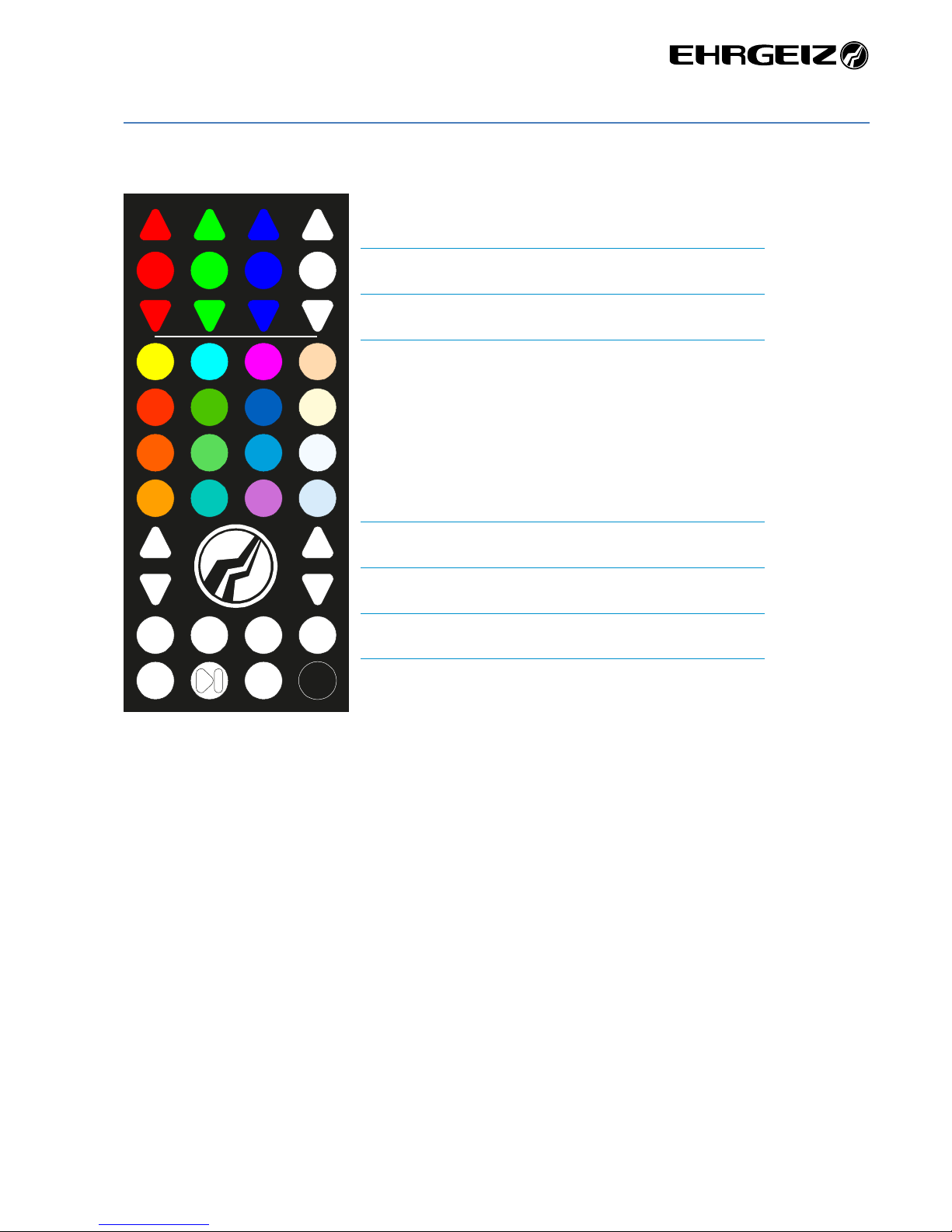
IR Control
The IR remote provides these functions:
Program Mode
You can choose AND Edit the 3 internal Programs.
A description will follow soon…
Increase colour intensity
Colour 0% / Colour 100 %
Decrease colour intensity
Choose a color
Increase speed / intensity
Decrease speed / intensity
Choose an internal program
Choose if program does a chase or fade; Pause program; blackout
chase fade black
P 1 P 2 P 3 auto
dimmer
speed

Operations →DMX Modes
14
DMX Modes
You can set up your Fusion 2 in 8 different DMX Modes:
Standard
Page 15; Uses 12 DMX channels
Advanced
Page 15; Uses 17 DMX channels
Pattern
Page 16; Uses 27 DMX channels
RGBW
Page 16; Uses 4 DMX channels
Compressed
Page 17 Uses 6 DMX channels
Pixel
Page 17 Uses 92 DMX channels
Pixel RGBW
Page 18 Uses 80 DMX channels
Pixel Dim
Page 18 Uses 32 DMX channels

Operations →DMX Modes
15
Standard
CH
Function
1
Colour Wheel (see Colourwheel channel chart)
2
Red
3
Green
4
Blue
5
White
6
Shutter effects (see Shutter effects channel chart)
7
Dimmer
8
CTO
9
Pattern
10
Pattern Speed
11
Pattern Fade
12
Control (see Control channel chart)
Advanced
CH
Function
1
Colour Wheel (see Colourwheel channel chart)
2
Red
3
Red fine
4
Green
5
Green fine
6
Blue
7
Blue fine
8
White
9
White fine
10
Shutter effects (see Shutter effects channel chart)
11
Dimmer
12
Dimmer fine
13
CTO
14
Pattern
15
Pattern Speed
16
Pattern Fade
17
Control (see Control channel chart)

Operations →DMX Modes
16
Pattern
CH
Function
1
Colour Wheel (see Colourwheel channel chart)
2
Red
3
Green
4
Blue
5
White
6
Shutter effects (see Shutter effects channel chart)
7
Dimmer
8
CTO
9
Control (see Control channel chart)
10
Pattern 1
11
Pattern 1 Speed
12
Pattern 1 Fade
13
Pattern 1 Red
14
Pattern 1 Green
15
Pattern 1 Blue
16
Pattern 1 White
17
Pattern 1 Shutter
18
Pattern 1 Dimmer
19
Pattern 2
20
Pattern 2 Speed
21
Pattern 2 Fade
22
Pattern 2 Red
23
Pattern 2 Green
24
Pattern 2 Blue
25
Pattern 2 White
26
Pattern 2 Shutter
27
Pattern 2 Dimmer
RGBW
CH
Function
1
Red
2
Green
3
Blue
4
White

Operations →DMX Modes
17
Compressed
CH
Function
1
Red
2
Green
3
Blue
4
White
5
Shutter effects (see Shutter effects channel chart)
6
Dimmer
Pixel
CH
Function
1
Colour Wheel (see Colourwheel channel chart)
2
Red
3
Green
4
Blue
5
White
6
Shutter effects (see Shutter effects channel chart)
7
Dimmer
8
CTO
9
Pattern
10
Pattern Speed
11
Pattern fade
12
Control (see Control channel chart)
13
Red 1
14
Green 1
15
Blue 1
16
White 1
17
Red 2
18
Green 2
19
Blue 2
20
White 2
…
89
Red 20
90
Green 20
91
Blue 20
92
White 20
Operations →DMX Modes
18
Pixel RGBW
CH
Function
1
Red 1
2
Green 1
3
Blue 1
4
White 1
5
Red 2
6
Green 2
7
Blue 2
8
White 2
…
77
Red 20
78
Green 20
79
Blue 20
80
White 20
Pixel Dim
CH
Function
1
Colour Wheel (see Colourwheel channel chart)
2
Red
3
Green
4
Blue
5
White
6
Shutter effects (see Shutter effects channel chart)
7
Dimmer
8
CTO
9
Pattern
10
Pattern Speed
11
Pattern Fade
12
Control (see Control channel chart)
13
Dimmer 1
14
Dimmer 2
…
32
Dimmer 20
Table of contents
Other Ehrgeiz Lighting Equipment manuals


Popular Lighting Equipment manuals by other brands


ADJ
ADJ Mega Bar RGBA User instructions

Fulton Hogan
Fulton Hogan ESTOP Operation & service manual

Sygonix
Sygonix SY-4697892 operating instructions

Briteq
Briteq BEAMSPOT1-TRIAC NW Operation manual

Deco Lighting
Deco Lighting D464-L installation instructions

Daintree
Daintree GE cirrent Tetra Rigid Light Bar installation guide