EINHELL E-Stand User manual

Art.-Nr.: 43.106.10 I.-Nr.: 11011
Original operating instructions
Base frame
E-Stand
Anleitung_E_Stand_SPK7:_ 30.06.2011 11:20 Uhr Seite 1

2
Read and follow the operating instructions and safety information
before using for the first time.
Anleitung_E_Stand_SPK7:_ 30.06.2011 11:20 Uhr Seite 2
3
1
F
B
C
A
A
B
FD
C
A
E
J
J
J
2
B
C
A
B
C
A
E
F
DF
Anleitung_E_Stand_SPK7:_ 30.06.2011 11:20 Uhr Seite 3

4
4
C
A
3
A
E
F
BC
D
GHI
J
K
Q
SR
L
M
N
J
JJ
5
C
N
A
Anleitung_E_Stand_SPK7:_ 30.06.2011 11:20 Uhr Seite 4
5
67
H,G
89
10
A
B
C
A
B
C
L
L
K, I
E
A
B
C
C
11
E
C
L
BA
Anleitung_E_Stand_SPK7:_ 30.06.2011 11:20 Uhr Seite 5
6
13
12
15a
16
14
B
F
B
F
A
C
E
K, I
F
B
D
B
L
B
F
D
K, I
15b
F
L
B
Anleitung_E_Stand_SPK7:_ 30.06.2011 11:20 Uhr Seite 6
7
17 18a
2.
2.
1.
1.
E
C
F
E
F
B
CE
E
B
F
18b F
E
B
C
B
2.
1.
19
Z
20
MM
M
J
J
21
M
Anleitung_E_Stand_SPK7:_ 30.06.2011 11:20 Uhr Seite 7

8
Q
R
22 23
Anleitung_E_Stand_SPK7:_ 30.06.2011 11:20 Uhr Seite 8

GB
9
Important!
When using equipment, a few safety precautions
must be observed to avoid injuries and damage.
Please read the complete operating manual of the
base frame and of your tool with due care. Keep this
manual in a safe place, so that the information is
available at all times. If you give the equipment to
any other person, give them these operating
instructions as well.
We accept no liability for damage or accidents which
arise due to non-observance of these instructions
and the safety information.
1. Safety information
Please refer to the information included in delivery
with your electrical tool (for example RT-XM 305 and
RT-SM 430) for its safety instructions.
CAUTION!
Read all safety regulations and instructions.
Any errors made in following the safety regulations
and instructions may result in an electric shock, fire
and/or serious injury.
Keep all safety regulations and instructions in a
safe place for future use.
1.1 Instructions for the base frame
The machine must be set up where it can stand
safely. Make sure that the ground in your work-
place is tidy, even and strong.
Make sure the saw is fixed securely on the base
frame.
Keep children away from the machine when it is
connected to the power supply
Do not let visitors contact tool or extension cord.
All visitors should be kept away from work area.
Store idle tools. When not in use, tools should be
stored in dry, high or locked up places, out of the
reach of children.
It is imperative to observe the accident prevention
regulations in force in your areas as well as all
other generally recognized rules of safety.
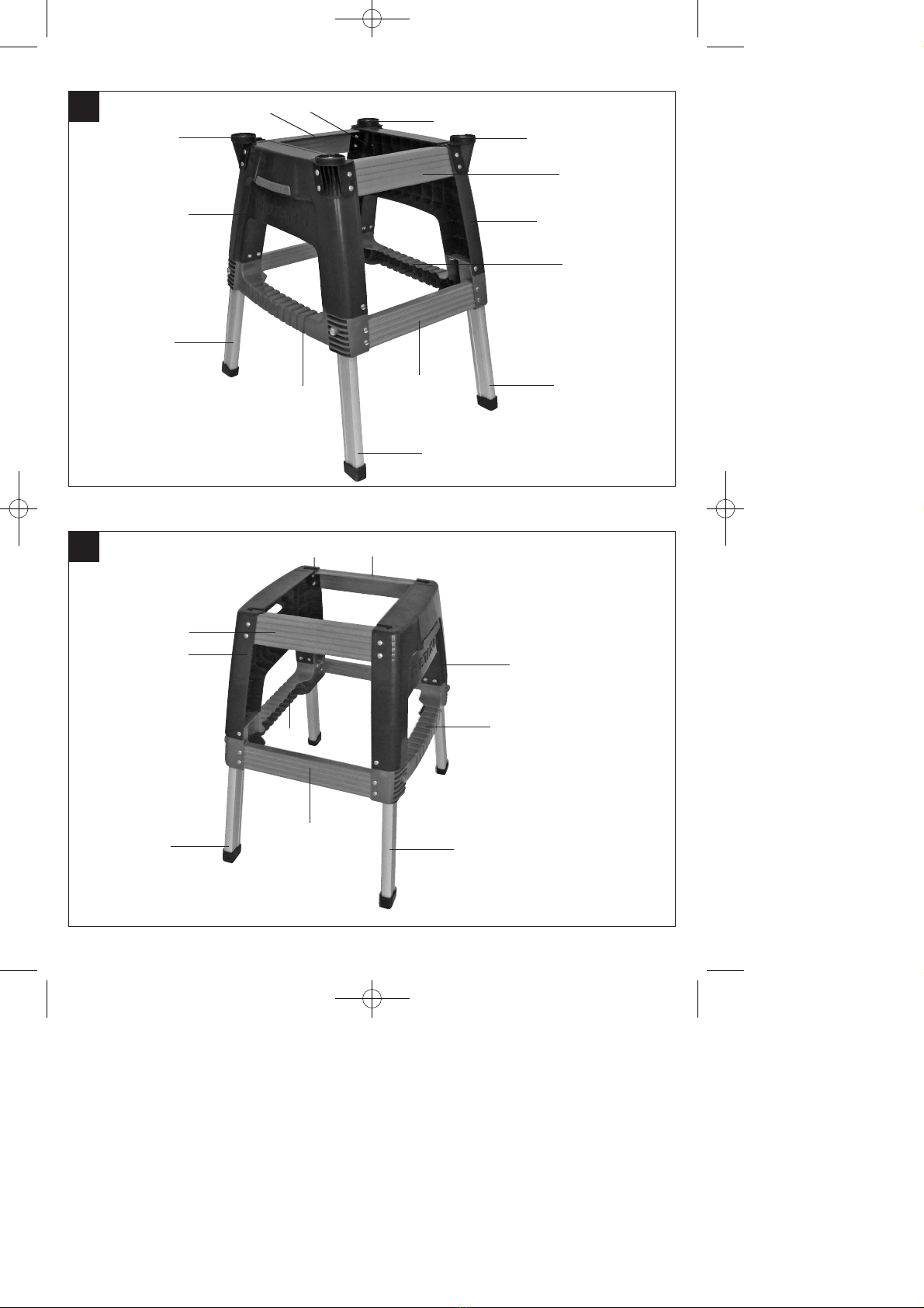
2. Layout
Base frame (Fig. 1-3)
A. Support feet
B. Side part
C. Intermediate strut
D. Corner reinforcement
E. Bottom cross struts
F. Top cross struts
J. Saw mount (for RT-SM 430 only)
3. Supplied package (Fig. 1-3)
4x Support feet (A)
2x Side parts (B)
2 x Intermediate struts (C)
4 x Corner reinforcements (D)
2 x Bottom cross struts (E)
2 x Top cross struts (F)
4 x Nuts (G)
4 x Washers (H)
36 x Nuts (I)
4 x Saw mount (J)
36 x Washers (K)
36 x Screws (L)
4 x Allen screws (M)
4 x Screws (N)
4x Washers (Q)
4x Cap nuts (R)
4x Screws (S)
4. Proper use
This base frame is designed as base for the mitre
saw RT-XM 305 and RT-SM 430.
The item is to be used only for its prescribed
purpose. Any other use is deemed to be a case of
misuse. The user / operator and not the
manufacturer will be liable for any damage or injuries
of any kind caused as a result of this.
Please note that our equipment has not been
designed for use in commercial, trade or industrial
applications. Our warranty will be voided if the
machine is used in commercial, trade or industrial
businesses or for equivalent purposes.
Sawing machines are to be operated only with
suitable saw blades. It is prohibited to use any type
of cutting-off wheel.
To use the machine properly you must also observe
the safety regulations, the assembly instructions and
Anleitung_E_Stand_SPK7:_ 30.06.2011 11:20 Uhr Seite 9

GB
10
the operating instructions to be found in this manual.
All persons who use and service the machine have
to be acquainted with this manual and must be
informed about its potential hazards.
It is also imperative to observe the accident
prevention regulations in force in your area.
The same applies for the general rules of
occupational health and safety.
The manufacturer shall not be liable for any changes
made to the machine nor for any damage resulting
from such changes.
Even when the machine is used as prescribed it is
still impossible to eliminate certain residual risk
factors. The following hazards may arise in
connection with the machineʼs construction and
design:
Contact with the saw blade in the uncovered saw
zone.
Reaching into the running saw blade (cut
injuries).
Kick-back of workpieces and parts of workpieces.
Saw blade fracturing.
Catapulting of faulty carbide tips from the saw
blade.
Damage to hearing if essential ear-muffs are not
worn.
Harmful emissions of wood dust when the
machine is used in closed rooms.
5. Technical data
Weight ca. 7 kg
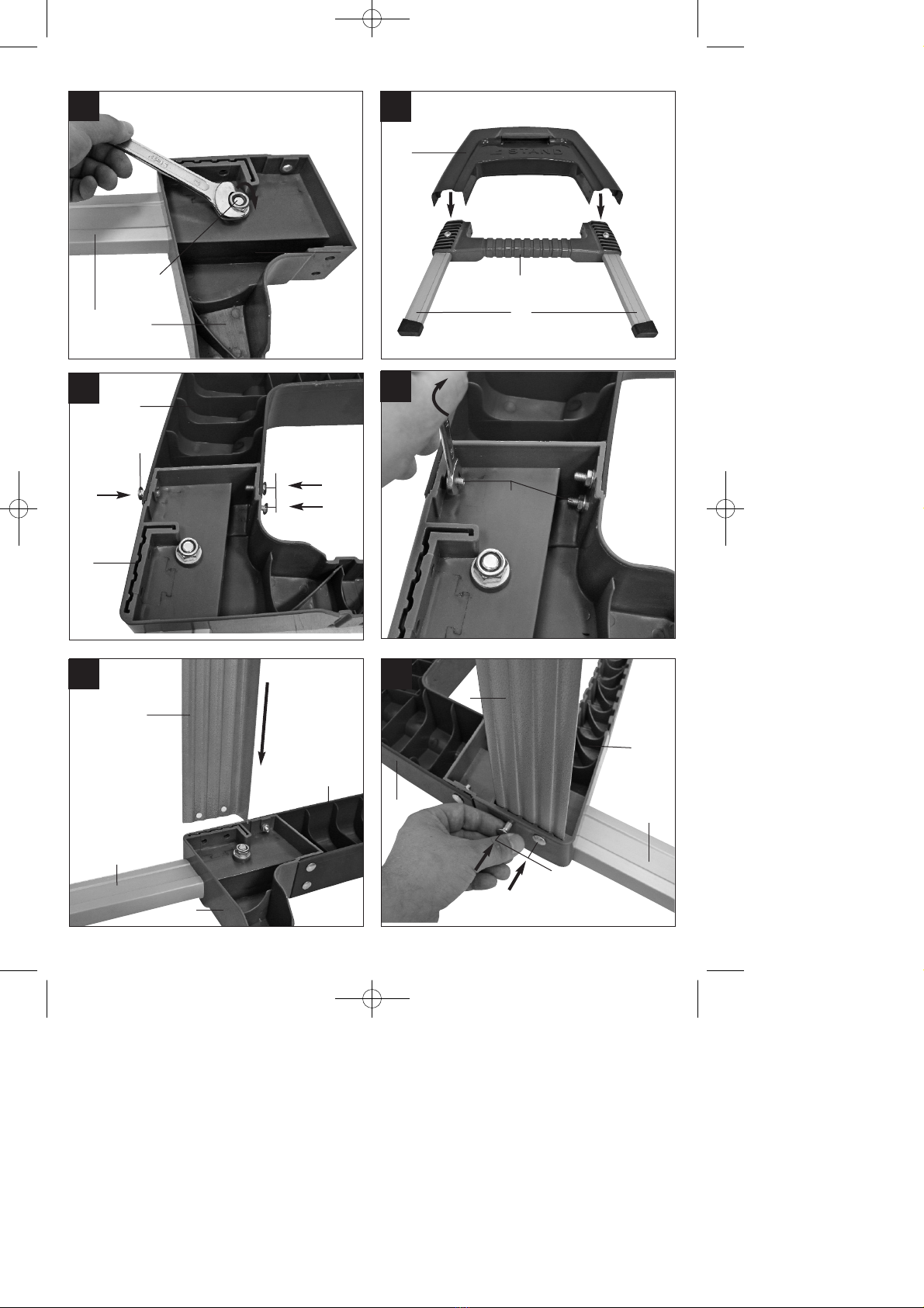
6. Assembling the base frame and
fixing the RT-SM 430 to the base frame
(Figs. 1, 4-14, 15a, 16-18a, 19-21)
1. Insert the support feet (A) from underneath into
the intermediate struts (C) as shown in Fig. 4.
Ensure that the rubber stoppers on the support
feet (A) are aligned so that their support surfaces
are leveled.
2. Screw the support feet (A) to the intermediate
struts (C) as shown in Figs. 5-6 using the screws
(N), washers (H) and nuts (G).
3. Slide the side part (B) from the top over the
intermediate struts (C) (Fig. 7).
4. Screw the side part (B) to the intermediate struts
(C) using three screws (L), washers (K) and nuts
(I) at each connection point (Figs. 8-9).
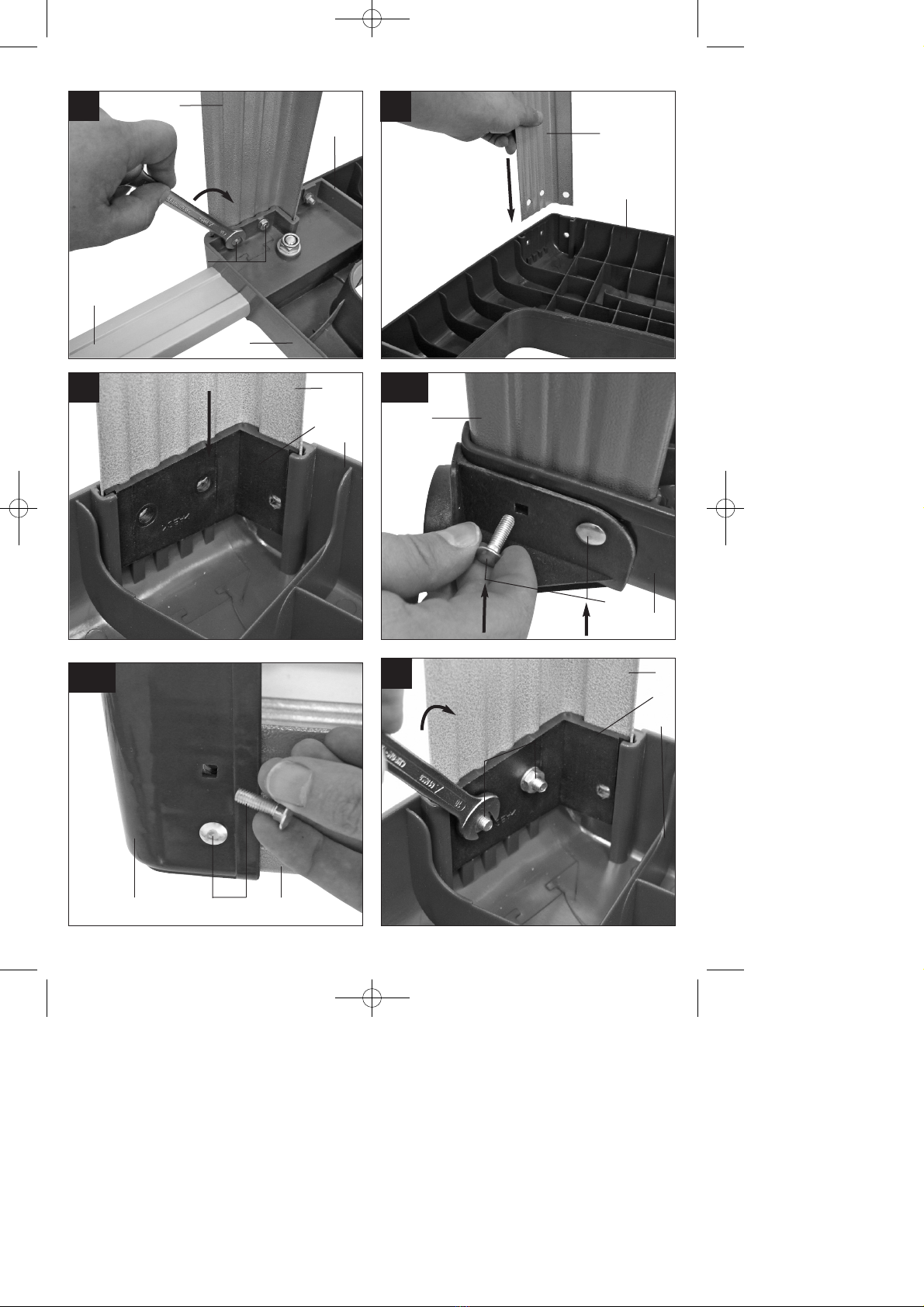
5. Assemble the other part of the base frame as
described above in step 1-4.
6. Take one of the assembled parts (no matter
which one) and insert the two bottom cross struts
(E) as far as possible into the appropriate
openings of the intermediate strut (C)
(Fig. 10). Screw the bottom cross struts (E) to
the intermediate strut (C) using two screws (L),
washers (K) and nuts (I) at each connection
point, as shown in Figs. 11-12.
7. On the same part of the base frame, slide the
two top cross struts (F) as far as possible into the
appropriate openings of the side part (B) (Fig.
13). Insert one corner brace (D) into each
opening of the side part (B). Note that the corner
braces (D) only fit one way on the base frame.
This is the case when the holes in the side part
(B), the top cross struts (F) and the corner
braces (D) line up (Fig. 14).
8. Fasten two of the saw mounts (J) onto the same
part of the base frame as shown in Fig. 15a.
Note that the saw mounts (J) only fit one way on
the base frame. This is the case when the holes
in the side part (B), the top cross struts (F), the
corner braces (D) and the saw mounts (J) are
aligned (Fig.15a).
9. Screw the top cross struts (F), corner braces (D),
side part (B) and saw mounts (J) together, as
shown in Figs. 15a-16 using two screws (L),
washers (K) and nuts (I) each time.
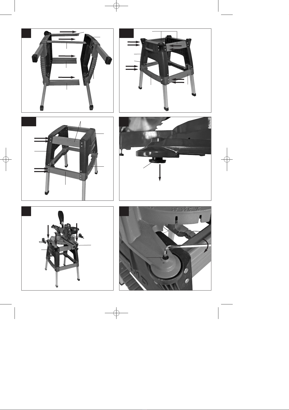
10. Insert the two base frame parts in such a way
that the bottom and top cross struts (E, F) are
positioned in the relevant openings on the side
part (B) and the intermediate strut (C) (Fig. 17).
11. Screw the bottom cross struts (E) to the second
part of the base frame as described in step 6
(Fig. 18a/1.).
12. Screw the top cross struts (F) to the second part
of the base frame as described in step 7 (Fig.
18a/2.).
13. Fasten the other two saw mounts (J) onto the
second part of the base frame as described in
step 8 (Fig. 18a/2.).
14. Pull the four rubber buffers (Z) from the bottom
side of the saw (Fig. 19).
15. Place the saw onto the base frame, align the
holes in which the rubber stops (Z) have been
with the 4 holes on the top side of the saw
mounts (J). Now insert the 4 screws (M) from
above through the saw feet and screw the saw to
the saw mounts (J) (Figs. 20-21).
Anleitung_E_Stand_SPK7:_ 30.06.2011 11:20 Uhr Seite 10
Other manuals for E-Stand
1
This manual suits for next models
1
Table of contents
Other EINHELL Power Tools Accessories manuals


Popular Power Tools Accessories manuals by other brands


ADAMAS
ADAMAS B32 Instructions for use

STEINEL PROFESSIONAL
STEINEL PROFESSIONAL 4007841009595 quick start guide

Echo
Echo Speed-Feed Universal 400 LH/RH Installation and loading instructions

SCHUNK
SCHUNK ROTA TB-TBS-EP Assembly and operating manual

Schmid
Schmid RAPID Secure XL Operation instructions

Drill Master
Drill Master 360X user guide


