Elan VIA!4.0-EM User manual

VIA!4.0-EM
VIA!7.0-EM
VIA!10.0-EM
4"/7"/10" Color LCD Touch Panels
INSTALLATION MANUAL

Important Information
NOTE: This equipment has been tested and found to comply with the
limits for a Class B digital device, pursuant to Part 15 of the FCC Rules.
These limits are designed to provide reasonable protection against
harmful interference in a residential installation. This equipment gener-
ates, uses and can radiate radio frequency energy and, if not installed
and used in accordance with the instructions, may cause harmful inter-
ference to radio communications. However, there is no guarantee that
interference will not occur in a particular installation.
If this equipment does cause harmful interference to radio or television
reception, which can be determined by turning the equipment off and
on, the user is encouraged to try to correct the interference by one or
more of the following measures:
• Reorient or relocate the receiving antenna.
• Increase the separation between the equipment and receiver.
• Connect the equipment into an outlet on a circuit different from that
to which the receiver is connected.
• Consult the dealer or an experienced radio/TV technician for help.
Caution: Changes or modifications not expressly approved by ELAN
could void the user’s authority to operate this equipment.

© ELAN Home Systems 2007 • All rights reserved. Page 1
ELAN HOME SYSTEMS VIA!4.0-EM/VIA!7.0-EM/VIA!10.0-EM
Contents
1. Introduction ......................................................................................2
Features ..............................................................................................2
2. System Design & Applications.................................................3
Planning ..............................................................................................3
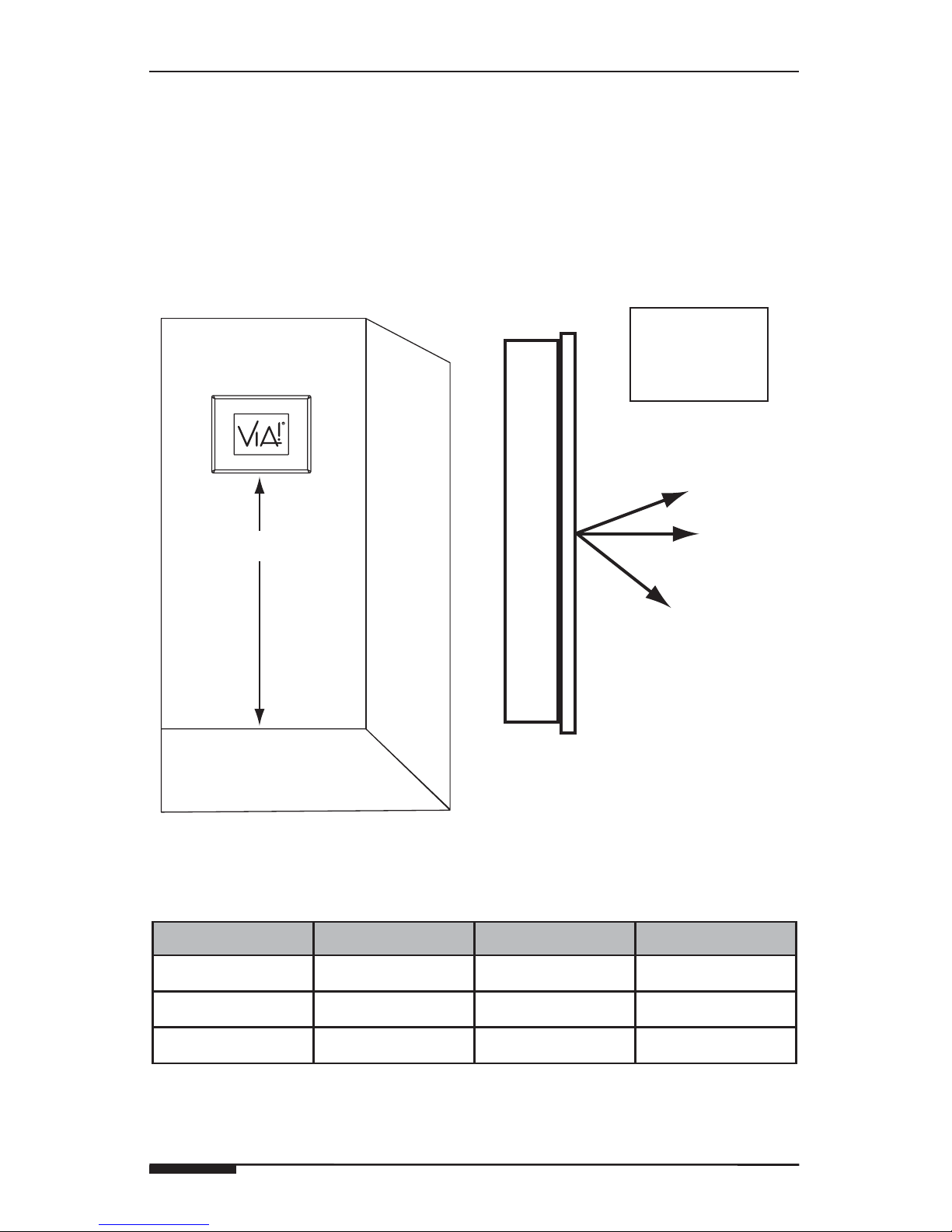
Mounting Height...............................................................................4
Applications .......................................................................................5
Stand-Alone/Home Theater.............................................................5
Stand-Alone/Home Theater - Expanded.........................................6
ELAN S12 Multi-Room A/V Controller.............................................7
ELAN S8 Multi-Room A/V Controller...............................................8
ELAN S6 Integrated Multi-Room Controller ...................................9
ELAN Z•System ...............................................................................10
RS-232 Controlled Devices (Regardless of System Type) ..................11
3. Installation/Connections ............................................................12
Installation ..........................................................................................18
ELAN Precision Panels and Wall Plates .........................................18
Pre-Wire ..............................................................................................20
Control, Status, Power.....................................................................20
Video.................................................................................................20
Video Termination Switch..................................................................21
Video In/Loop Out Configuration .......................................................21
Rough-In .............................................................................................23
New Construction ............................................................................23
Retro-Fit............................................................................................24
Cutout Dimensions ..........................................................................26
Mounting...........................................................................................27
Removal From Wall (Winglets Deployed)............................................28
Connections .......................................................................................29
Stand-Alone/Home Theater.............................................................29
ELAN System12 and System8.........................................................30
ELAN System6 (w/ PVIA Wall Plate) .............................................. 31
ELAN Z•System ...............................................................................32
Increasing Wire Runs Beyond the 200 Foot Maximum .................33
Stand-Alone.....................................................................................33
ELAN S12 and S8.............................................................................34
ELAN S6 ..........................................................................................34
ELAN Z•System ...............................................................................35
External Power Connector ................................................................35
4. Operation ...........................................................................................36
5. Troubleshooting ..............................................................................38
Appendix A: Specifications ...........................................................39
Appendix B: Programming .............................................................40
Warranty ................................................................................. Back Page

VIA!4.0-EM/VIA!7.0-EM/VIA!10.0-EM E L A N H O M E S Y S TEMS
Page 2 © ELAN Home Systems 2007 • All rights reserved.
1. Introduction
The VIA!®4.0-EM, VIA!®7.0-EM and VIA!®10.0-EM Color LCD Touch Panels
provide an intelligent, affordable solution for controlling audio, video, and
automation equipment in a multi-room environments or as a stand-alone
controllers (in a Home Theater, for example). With System and Local IR
control, RS-232 control, and full-motion video display, these touch panels
have all of the features that have made ELAN’s award-winning VIA!®6.4 and
VIA!®Valet6.4 Touch Panels the most successful products in their category.
Touch Screen Technology
The VIA!-EM lineup utilize a polyester plastic film suspended over a glass
panel which is then adhered to the front of a color LCD (Liquid Crystal
Display) screen. Depressing the polyester film with a finger allows the film
to touch the glass panel underneath, generating a location signal that is
read by the electronics. The color LCD display is an active matrix TFT Liquid
Crystal Display. Please use fingers only when operating this unit. Do not use
pens, pencils, etc. as these may damage the polyester film.
Features
• 4" / 7" / 10" Color Active Matrix TFT Liquid Crystal Display
• Full Touchscreen Capabilities
• VIA!7.0EM & VIA!10.0-EM - Widescreen, Landscape Aspect Ratio
• IR and RS-232 Control Options
• Full-Motion Color Video Capabilities
• Easy, Powerful VIA!®TOOLS Programming
• System, Local and Interface Ports
• Affordable!
Accessories
• Rough-In Brackets
VIA!40EMBKT
VIA!70EMBKT
VIA!100EMBKT
• Wall Frames
Standard and Euro Styles
Available in White, Light Almond, Almond, Ivory, Brown,
Black & Satin Chrome
• Precision Panels & Wall Plates
PVIA!1
PVIA!4
PVIA!10
SPP System Precision Panel

© ELAN Home Systems 2007 • All rights reserved. Page 3
ELAN HOME SYSTEMS VIA!4.0-EM/VIA!7.0-EM/VIA!10.0-EM
2. System Design & Applications
Planning
Before installing a VIA! Touch Panel, it is essential to have a detailed and
accurate system design. Talk with the homeowner to make sure all expecta-
tions and design goals are explored. The first step to a good design is to
map the system. It is advisable to mark up a copy of the house floor plan
with speaker, keypad, touch panel, volume control, and equipment locations,
etc. Make sure that all locations are decided upon before pre-wiring com-
mences so that all necessary wiring and installation hardware is in place.
It is essential that ALL system components are accounted for prior to the
pre-wire stage. After establishing design goals with the homeowner, make a
detailed list of all components. Include source equipment, keypads, touch
panels, volume controls, amplifiers, communications gear, etc. Gather up
any IR remote controls that may be necessary for final programming, or
ensure that the IR codes for all equipment to be installed are available in the
VIA!TOOLS IR Library.
When planning specific in-wall installation locations for LCD
touch panels, please keep the following tips in mind:
• When properly installed, nothing should be applying contact pressure
to the touch panel except for the operator’s finger. If something is
touching the touch screen window, a false signal can be generated,
causing the touch panel to respond incorrectly.
• Avoid installation in direct sunlight or strong ultraviolet light (such as
grow lamps for plants). This can degrade and discolor polyester film.
• Avoid installation over heat generating devices and/or in moist areas
where condensation can form on the polyester film. Both heat and
condensed moisture can affect touch screen performance.
• Avoid installation next to thermostats. The touch screen generates
heat that can affect thermostat control and readings.
• Avoid applying any foreign objects, such as adhesive labels, glue, etc.
to the touch screen’s polyester film. This can release chemicals that
can discolor the clear film.
• The touch panel/LCD assembly should not be mounted near electron-
ics that emit radio frequencies or electromagnetic interference (such
as CRT monitors, light dimmers, and some power supplies).
• Do not mount VIA! Touch Panels outdoors or in areas exceeding
the operating temperature range of -10° to +115°F (-23° to +46°C). If
the LCD display is over-heated, or its temperature reduced below the
recommended minimum, the liquid crystal polymer can be damaged
and the display image may not recover.

VIA!4.0-EM/VIA!7.0-EM/VIA!10.0-EM E L A N H O M E S Y S TEMS
Page 4 © ELAN Home Systems 2007 • All rights reserved.
Mounting Height
For optimal viewing, VIA! Touch Panels should be installed 56" to 60" from
the floor to the bottom of the frame when mounted in a wall. In custom
applications, factor in the viewing angles shown in Figure 2.1 and Table
2.1 and make sure that the graphics and video remain visible in the pro-
spective viewing location.
56" to 60"
Side View
Viewing
Angles
Up
Down
Optimal
Figure 2.1: Mounting Height and Viewing Angle
VIA!4.0-EM VIA!7.0-EM VIA!10.0-EM
Up Angle 35º 50º 45º
Down Angle 15º 70º 65º
Left/Right 50º 70º 65º
Table 2.1: Viewing Angles

© ELAN Home Systems 2007 • All rights reserved. Page 5
ELAN HOME SYSTEMS VIA!4.0-EM/VIA!7.0-EM/VIA!10.0-EM
Applications
Stand-Alone/Home Theater
VIA! Touch panels can be used for any Stand-Alone (non-ELAN) system
application or as a Home Theater controller. Figure 2.2 shows a basic appli-
cation using one VIA! Touch panel, a PVIA1 Wall Plate, and an ELAN IRD4
Amplified IR Connection Block to control a stack of A/V equipment.
TO SC-4
PWR1
IR
OUT
VIDEO IN
PWR9
Digital Music Server
Satellite
DVD
IR Emitter
IR Emitter
IR Emitter
Amplified IR
Connection Block
PVIA1
PWR1
PWR2
3.5mmMono
to Quad
Interconnect
Cable
(included w/ IRD4)
Figure 2.2: Stand-Alone/Home Theater Application - Basic

VIA!4.0-EM/VIA!7.0-EM/VIA!10.0-EM E L A N H O M E S Y S TEMS
Page 6 © ELAN Home Systems 2007 • All rights reserved.
Stand-Alone/Home Theater - Expanded
Stand-Alone systems (without an ELAN multi-room controller) can be as
simple as one VIA! Touch Panel controlling one IR source, or as complex as
multiple VIA!s, Olé Touchpads, keypads, and IR sensors all controlling many
IR sources. Figure 2.3 shows four VIA! Touch Panels, a PVIA4 Wall Plate
and an IRD4 IR Distribution Block controlling a stack of A/V gear.
PVIA4
PVIA-4
VIDEO
IN
1234
+16VDC
POWER
9 VDC
SENSE
INPUTS
IR
OUT
12
34
ALL
SYS
SENSE
TO SC-4
12
34
16 VDC/
4A
PWR4
Digital Music Server
Satellite
DVD
IR Emitter
IR Emitter
IR Emitter
Amplified IR
Connection Block
PWR2
3.5mmMono
to Quad
Interconnect
Cable
(included w/ IRD4)
Figure 2.3: Stand-Alone Application - Expanded

© ELAN Home Systems 2007 • All rights reserved. Page 7
ELAN HOME SYSTEMS VIA!4.0-EM/VIA!7.0-EM/VIA!10.0-EM
ELAN S12 Multi-Room A/V Controller
Use either ELAN's PS12 Precision Panel or SPP System Precision Panel
when installing VIA! Touch panels in an S12-based application. A PVIA Wall
Plate is not necessary when using VIA!s with an S12; the PS12 or SPP has
all necessary provisions. A PWR4 or PWR10 Power Supply must be used
when connecting VIA! Touch Panels to the PS12. Figure 2.6 shows eight
VIA!s and a PS12 or SPP connected to an ELAN S12.
PS12
XM FM
12345 6 MONO
+
-
ZONE LOCAL
22
ZONE LOCAL
33
ZONE LOCAL
4
ZONE
4
LOCAL
55
ZONE LOCAL
6
ZONE
6
LOCAL
8
LOCAL
8
ZONE
7
LOCAL
7
ZONE VIA!POWER
16VDC / 10A
16VDC / 4A
VIA!NET
TO SENSE INPUTS
USE STEREO 3.5mm PLUGS ONLY
EXT IR ANTENNA
S12
+-
16VDC
10.0A
PWR10
11
SPP
+
--
VIA!NET
16VDC / 10A
16VDC / 4A
16VDC/1.5A
1
ZONE
2
ZONE
3
ZONE
4
ZONE
SS/SC4
5
ZONE
6
ZONE
7
ZONE
8
ZONE
TO SENSE INPUTSEXT IR
123
USE STEREO 3.5mm PLUGS ONLY
456
1
TRIGGERS
234
5678
POWER
OR
Figure 2.6: ELAN S12 Application

VIA!4.0-EM/VIA!7.0-EM/VIA!10.0-EM E L A N H O M E S Y S TEMS
Page 8 © ELAN Home Systems 2007 • All rights reserved.
ELAN S8 Multi-Room A/V Controller
ELAN's SPP (System Precision Panel) is designed to work with any S Series
Multi-Room controller. Figure 2.7 shows ten VIA! Touch Panels connected
to a System8 (S8.6AV or S8.6P) Multi-Room A/V Controller using an SPP. No
PVIA Wall Plate is necessary when using VIA!s with an S8; the SPP has all
necessary provisions. A PWR4 or PWR10 Power Supply must be used when
connecting VIA! Touch Panels to the SPP.
Note: The SPP can be used with ANY ELAN S Series Multi-Room
Controller. Connections are identical for ELAN S6, S8 or S12 appli-
cations.
SPP
S8.6/
S6
+-
16VDC
10.0A
PWR10
+
--
VIA!NET
16VDC / 10A
16VDC / 4A
16VDC/1.5A
1
ZONE
2
ZONE
3
ZONE
4
ZONE
SS/SC4
5
ZONE
6
ZONE
7
ZONE
8
ZONE
TO SENSE INPUTSEXT IR
123
USE STEREO 3.5mm PLUGS ONLY
456
1
TRIGGERS
234
5678
POWER
Figure 2.7: S6/S8.6/S12/SPP Application

© ELAN Home Systems 2007 • All rights reserved. Page 9
ELAN HOME SYSTEMS VIA!4.0-EM/VIA!7.0-EM/VIA!10.0-EM
ELAN S6 Integrated Multi-Room Controller
The VIA!4.0-EM’s affordability makes it an ideal candidate for System6 (S6)
applications, although VIA!7.0-EM and VIA!10.0-EM Touch Panels may cer-
tainly be used, as well. Use a PVIA Wall Plate appropriate for the number of
VIA!s to be installed or an SPP System Precision Panel. Figure 2.4 shows
four VIA!4.0-EM's and a PVIA4 configured for use with an ELAN S6.
Note: The SPP can be used with ANY ELAN S Series Multi-Room
Controller. Connections are identical for ELAN S6, S8 or S12 appli-
cations. See Figure 2.7 for details
PVIA-4
VIDEO
IN
1234
+16VDC
POWER
9 VDC
SENSE
INPUTS
IR
OUT
12
34
ALL
SYS
SENSE
TO SC-4
12
34
PVIA4
S6
16 VDC/
4A
PWR4
Figure 2.4: ELAN S6 Application

VIA!4.0-EM/VIA!7.0-EM/VIA!10.0-EM E L A N H O M E S Y S TEMS
Page 10 © ELAN Home Systems 2007 • All rights reserved.
ELAN Z•System
Advanced features like Audio Detect and Spatial Enhancement can be
accessed using a VIA! in an ELAN Z•System. Figure 2.5 shows how to con-
figure four VIA!s using a PVIA4 and a PZ6 Precision Panel for Z•Systems.
PZ6
Z630 X 2
PVIA-4
VIDEO
IN
1234
+16VDC
POWER
9 VDC
SENSE
INPUTS
IR
OUT
12
34
ALL
SYS
SENSE
TO SC-4
12
34
PVIA4
16 VDC/
4A
PWR4
Figure 2.5: Z•System Application

© ELAN Home Systems 2007 • All rights reserved. Page 11
ELAN HOME SYSTEMS VIA!4.0-EM/VIA!7.0-EM/VIA!10.0-EM
RS-232 Controlled Devices (Regardless of System Type)
By adding an SC-4 Serial Controller or SS1 System Station to any system
using VIA! Touch Panels, powerful RS-232 control becomes possible for
a wide assortment of devices such as security systems, lighting systems,
HVAC, spa control, A/V gear, etc. Use the appropriate PVIA Wall Plate or
Precision Panel for the number of VIA! Touch Panels in the system and the
system type. When installing an SC-4/SS1 in an S12 or S8 system, a PVIA
Wall Plate is not needed; the SPP or PS12 Precision Panel has all necessary
provisions.
VIA!SC4
PVIA10
PVIA4
TO SC-4
PWR1
IR
OUT
VIDEO IN
PWR9
PVIA-4
VIDEO
IN
1
1
2
2
3
3
4
4
+16VDC
POWER
9 VDC
SENSE
INPUTS
IR
OUT
1 2
3 4
ALL
SYS
SENSE
TO SC-4
1 2
3 4
PVIA1
SPP
RS-232
Devices
Stand-Alone, Z•Systems
S6, S8, or S12 Systems
or or
RS-232
Devices
SS1
or
or
+
--
VIA!NET
16VDC / 10A
16VDC / 4A
16VDC/1.5A
1
ZONE
2
ZONE
3
ZONE
4
ZONE
SS/SC4
5
ZONE
6
ZONE
7
ZONE
8
ZONE
TO SENSE INPUTSEXTIR
123
USE STEREO 3.5mm PLUGS ONLY
45
6
1
TRIGGERS
234
5678
POWER
HOST RS-232
ELAN RS-232
HOST
ELAN
COM 1
COM 3
COM 2
COM 4
COM1
COM2
COM3
COM4
ETHERNET
LINK
RX/TX
IR-LINK SENSE INPUTS
123
456
ALL IR OUTPUT
EXT IR INPUT
IR OUTPUTS
1
7
2
8
3
9
4
10
5
11
6
12 VIA-NET
IR
PWR
VIA!2SS1
POWER
12VDC
0.5 AMPS
-+
LEXINGTON, KY • MADE IN CHINA
MODEL: VIA2SS1
WARNING : DONOT REMOVE COVER.
NO USER SERVICEABLE PARTSINSIDE.
REFER SERVICE TO ELAN-APPROVED
SERVICETECHNICIAN.
PWR
GND
NC
COM
NO
PWR
GND
NC
COM
NO
PWR
GND
NC
COM
NO
PWR
GND
NC
COM
NO
PWR
GND
NC
COM
NO
PWR
GND
NC
COM
NO
PWR
GND
NC
COM
NO
PWR
GND
NC
COM
NO
PWR
GND
DC RELAYPWR RELAY1 RELAY2 RELAY 3 RELAY 4 RELAY5 RELAY6 RELAY7 RELAY 8
HOST RS-232
ELAN RS-232
HOST
ELAN
COM 1
COM 3
COM 2
COM 4
COM1
COM2
COM3
COM4
ETHERNET
LINK
RX/TX
IR-LINK SENSE INPUTS
123
456
ALL IR OUTPUT
EXT IR INPUT
IR OUTPUTS
1
7
2
8
3
9
4
10
5
11
6
12 VIA-NET
IR
PWR
VIA!2SS1
POWER
12VDC
0.5 AMPS
-+
LEXINGTON, KY • MADE IN CHINA
MODEL: VIA2SS1
WARNING: DONOT REMOVE COVER.
NO USER SERVICEABLE PARTSINSIDE.
REFER SERVICE TO ELAN-APPROVED
SERVICETECHNICIAN.
PWR
GND
NC
COM
NO
PWR
GND
NC
COM
NO
PWR
GND
NC
COM
NO
PWR
GND
NC
COM
NO
PWR
GND
NC
COM
NO
PWR
GND
NC
COM
NO
PWR
GND
NC
COM
NO
PWR
GND
NC
COM
NO
PWR
GND
DC RELAYPWR RELAY1 RELAY2 RELAY 3 RELAY 4 RELAY5 RELAY6 RELAY7 RELAY 8
COM 1
COM 3
COM 2
COM 4
NETWORK
INTERFACE
ELAN
RS-232
OUT
POWER
16VDC
COM 1
COM 3
COM 2
COM 4
NETWORK
INTERFACE
ELAN
RS-232
OUT
POWER
16VDC
VIA!SC4
SS1
Figure 2.7: RS-232 Controlled Devices

VIA!4.0-EM/VIA!7.0-EM/VIA!10.0-EM E L A N H O M E S Y S TEMS
Page 12 © ELAN Home Systems 2007 • All rights reserved.
3. Installation/Connections
Each of the three VIA! Touch Panel models uses the same connectors and
hook up identically. All connections are located on the bottom of the unit and
include a System Port RJ-45 Connector, a Local Port RJ-45 Connector, an
External Power Connector and an IR Interface Port as well as a Composite
Video Input and Output.
123456
Figure 3.1 VIA! Connectors
Note: VIA!4.0_EM shown. Connectors are identical for VIA!7.0-EM
and VIA!10.0-EM
Connection Connector / Cable Type
1
Video Out F-Connector / RG-6 or RG-59
2
Video In F-Connector / RG6 or RG-59
3
System Port RJ-45 / CAT-5
4
Local Port RJ-45 / CAT-5
5
Interface Port Removable Screw Terminal / CAT-5
6
External Power Removable Screw Terminal /
2 Conductor 16/18 AWG
Table 3.1 VIA! Connectors

© ELAN Home Systems 2007 • All rights reserved. Page 13
ELAN HOME SYSTEMS VIA!4.0-EM/VIA!7.0-EM/VIA!10.0-EM
1
Video Out
This connection is used to send Video signals passed through the VIA! Touch
Panel from a video switcher or source component to another VIA! Touch
Panel, TV or Monitor.
2
Video In
This connection receives the Video Signal from a video switcher or source
component.
3
System Port
The System RJ-45 port provides required functionality for all system types.
Use this port when the VIA! is used in an ELAN Multi-Room Controller- based
System (ELAN S or Z•System). Use ELAN Standard RJ-45 Pinout configura-
tion (as shown in Figure 3.2).
Figure 3.2: ELAN RJ-45 Pinout
4
Local Port
The Local RJ-45 port provides an interface for use primarily with the VIA!
SR-1 Sense/Relay Module Local Port Connection (as well as other functions).
The Local Port is identical in function and pinout to the System Port.
COM PO RT POWER
16VDC
RELAY O U T PU T S
1/ 2 3/ 4 5/6
IR
INPUT
RS-232
IN
RS-232
THRU
VIA!
LOCAL
PORT
VIA!40-EM/VIA!7.0-EM/VIA!7.0-EM VIA! SR-1
Figure 3.3: Local Port

VIA!4.0-EM/VIA!7.0-EM/VIA!10.0-EM E L A N H O M E S Y S TEMS
Page 14 © ELAN Home Systems 2007 • All rights reserved.
5
Interface Port
Use this connector when utilizing local control features such as local source
control, local IR receivers, or sense-enabled automated sequences.
IR OUT (LOC)
The IR OUT (LOC) port is typically used to control a device that is not part
of the main IR system, such as a TV or DVD player located within the same
room as the touch panel, or an ELAN Electronic Volume Control. IR is routed
to an emitter or IR distribution block connected to the IR OUT (LOC) in two
ways:
Any IR signal that is received from the Local IR Input is sent out of
the Local IR Output RJ-45 Port, the SYS IR Output RJ-45 Port and
the IR OUT (LOC) port from the Interface Port.
IR signals may be specified in programming as "Local" and be routed
through the Local IR OUT (LOC) port. See VIA!TOOLS "Help" file for
specific information about IR routing.
IR Emitter
IR + = White Stripe
GND = Black
IR OUT (LOC)
IR IN
GROUND
+12 VOLTS OUT
SENSE
Figure 3.4: Interface Port IR OUT (LOC) Connection
1.
2.

© ELAN Home Systems 2007 • All rights reserved. Page 15
ELAN HOME SYSTEMS VIA!4.0-EM/VIA!7.0-EM/VIA!10.0-EM
IR IN
The Local IR Input is typically used to connect an external IR receiver to the
touch panel. Typical applications include a plasma-friendly IR receiver (ELAN
IRS8EP, for example) placed near a TV, or an auxillary IR receiver placed in
an area more convenient than the location of the touch panel. Any IR signal
that is received from the Local IR Input is sent out the Local IR Output
RJ-45 Port, the System IR Output RJ-45 Port and the IR Out from the
Interface Port.
Connect IR IN, GROUND, and +12 VOLTS as shown in Figure 3.5.
+12VDC
G
IR
IRS8EP
Extreme Plasma
IR Sensor
IR OUT (LOC)
IR IN
GROUND
+12 VOLTS OUT
SENSE
Figure 3.5: Interface Port IR IN Connection

VIA!4.0-EM/VIA!7.0-EM/VIA!10.0-EM E L A N H O M E S Y S TEMS
Page 16 © ELAN Home Systems 2007 • All rights reserved.
Sense
The Sense Port allows a contact closure to trigger IR or RS-232 sequences
programmed in VIA!TOOLS. For example, use a motion sensor to activate
a contact closure and cause automated actions such as system power on,
drapes closed, and lights dimmed.
Connect SENSE and GROUND to a contact closure device as shown in
Figure 3.6.
Contact Closure
Device
IR Out (LOC)
IR In
Ground
+12 Volts Out
Sense
Figure 3.6: Interface Port Sense Connections

© ELAN Home Systems 2007 • All rights reserved. Page 17
ELAN HOME SYSTEMS VIA!4.0-EM/VIA!7.0-EM/VIA!10.0-EM
6
External Power
The External Power port allows VIA! Touch Panels to be powered with a two-
conductor 16/18 AWG wire from an external power supply or Precision Panel
connected to the removable screw terminal plug.
Connect +16 VOLTS and GROUND as shown in Figure 3.7.
GV+
External Power
Connector
Figure 3.7: External Power Connections

VIA!4.0-EM/VIA!7.0-EM/VIA!10.0-EM E L A N H O M E S Y S TEMS
Page 18 © ELAN Home Systems 2007 • All rights reserved.
Installation
ELAN Precision Panels and Wall Plates
VIA! Touch Panels require an ELAN Precision Panel or Wall Plate to function
properly. The specific application will determine the Precision Panel or Wall
Plate needed. Each of these panels provides a power supply of the correct
voltage (+16VDC) and amperage for the application being covered. In addi-
tion to power, these Precision Panels and Wall Plates have provisions for
critical connections like IR, GND, and System Status.
PVIA1
The PVIA1 is a single-gang
Decora®style wall plate designed to
support a single VIA! Touch Panel.
It has connections for Power, GND,
Sense/Status, IR, Video, and Serial
Control. It can be used in any applica-
tion including ELAN Multi-Room sys-
tems, or Stand-Alone systems.
PVIA4
The PVIA4 is a dual-gang wall plate
that provides power, control, and video
connectivity for up to four VIA! Touch
Panels. It can be used in any applica-
tion including ELAN Multi-Room sys-
tems, or Stand-Alone systems.
PVIA10
The PVIA10 is a Precision Panel
designed to provide power, control,
and video connectivity for up to ten
VIA! Touch Panels. It can be used in
any application including ELAN Multi-
Room systems, or Stand-Alone.
This manual suits for next models
2
Table of contents
Other Elan Touch Panel manuals