manuals.online logo
Brands
  1. Home
  2. •
  3. Brands
  4. •
  5. Eldat
  6. •
  7. Receiver
  8. •
  9. Eldat RCU01-4104M-01 User manual

Eldat RCU01-4104M-01 User manual

GB
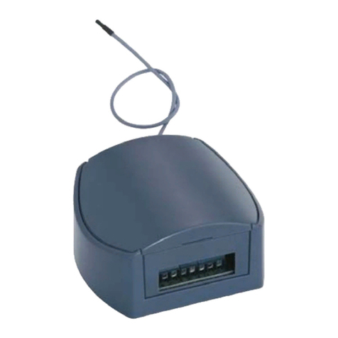
Universal Receiver RCU01 (4-Channel)
Models
RCU01-4104M-01: 433.92 MHz
RCU01-5004M-01: 868.3 MHz
Package Content
Universal Receiver incl. HF antenna,
Mounting accessories, Screw fittings set,
Operating instructions
Technical Data
Frequency: 433.92 or 868.30 MHz
Power supply: 230 V AC / 12-24 V DC
Output: 4 potential-free relay
contacts
Max. load: 230 V AC: see Table
30 V DC: 3 A / 90 W
Response time: approx. 1 second
Degree of protection: IP54
Operating temperature: -20°C to +60°C
Dimensions: 150 x 110 x 50 mm
Weight: approx. 500 g
Intended Use
The unit may only be used as a radio con-
trol system together with low voltage or
mains voltage devices!
The manufacturer shall not be liable for any
damage caused by improper or non-
intended use!
Safety Advice
Warning! While being pro-
grammed, the Universal Re-
ceiver is live!
Do not touch the terminals! Only use
suitable tools!
Carefully read through these instructions
before connecting and operating the Uni-
versal Receiver!
Electrical installation and programming
may only be carried out by a qualified
electrician!
Observe the applicable laws, standards
and regulations, particulary EN 60669!
Caution! The primary input of the Uni-
versal Receiver must be protected by a
50 mA fuse.
Have faulty units checked by the manufac-
turer!
Do not make any unauthorized alterations
or modifications to the unit!
Non-observance of the installation instruc-
tions may cause fire or other hazards.
Function
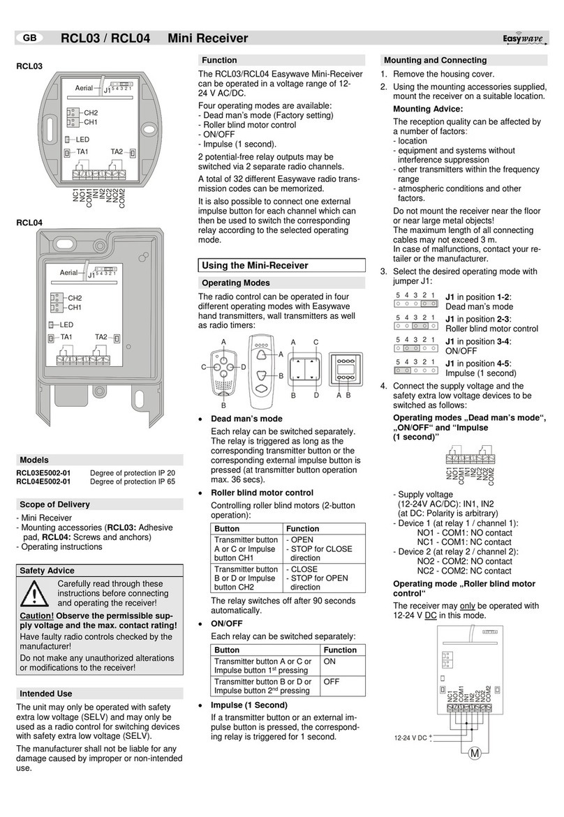
The unit is a universally applicable four
channel radio control system, which can be
operated both with low voltage and mains
voltage.
The Universal Receiver can memorize 4
transmission codes for each channel. For
each channel different operating modes can
be programmed: Impulse, ON/OFF (1- and
2-button operation), timer (30 seconds and
3 minutes), continuous and awning opera-
tion.
General Information
Do not mount the Universal Receiver near
the floor or near large metal objects!
The maximum length of all connecting
cables may not exceed 3 m.
The reception quality can be affected by a
number of factors:
•location, Transmitter
•equipment and systems without interfe-
rence suppression
•other transmitters within the frequency
range
•atmospheric conditions and other fac-
tors.
In case of malfunctions, please contact your
dealer or the manufacturer.
Connection Diagram
21
22
23
24
25
26
27
28
29
30
31
32
REL1
REL2
REL3
REL4
S1 Dip switch for memory
location select
DR1 Rotary switch for
operating mode select
H1 LED
TA1 – TA4 Programming buttons for
channels 1-4
REL1 – REL4 Relays 1-4 for
devices 1-4
V1 – V4 Connecting terminals for
relays 1-4
BU1 Antenna socket
ST1 Connecting terminal for
mains voltage 230 V AC
ST2 Connecting terminal for
low voltage 12-24 V DC
Start-Up
Start-up the Universal Receiver in three
steps:
1. Installing the Universal Receiver
2. Programming the operating mode
3. Memorizing the transmission codes
Installing the Universal Receiver
1. Unscrew the housing cover.
2. Use the screws and mollies supplied, to
mount the Universal Receiver on the
wall.
3. Connect the low voltage or mains
voltage devices to be switched to the
connecting terminals V1 to V4 according
to the connection plan. The connecting
terminals are plug-type terminals.
Max. load:
230 V AC: see Table of Loads
30 V DC: 3 A / 90 W
4. Connect the power supply cables to the
connecting terminal ST1 (mains voltage
230 V AC) or ST2 (low voltage 12-24 V
DC) according to the connection plan.
The connecting terminal ST1 is a plug-
type terminal.
Note: All cables are to be fed into the
Universal Receiver via the openings on
the bottom using the watertight PG
screw fittings.
5. Switch on the supply voltage. The LED
H1 lights up for approx. 1 sec.
6. Carry out a function check:
Press any button of the transmitter. The
LED H1 of the Universal Receiver
should flash rapidly.
Table of Loads (AC)
Type of load Max. load
230 V AC / 50Hz
Resistive load:
Light bulbs, 230 V
Halogen lamps etc.
8 A / 1,840 VA
Inductive load:
Halogen lamps with wound
transformers
(transformer at least 85%
loaded)
2.6 A / 600 VA
Non-compensated or series-
compensated fluorescent
lamps with ferromagnetic
ballast
8 A / 1,840 VA
Parallel-compensated
fluorescent lamps with
ferromagnetic ballast
2.6 A / 600 VA
Capacity EB:
electronic ballast, electronic
transformers etc.
4 A / 920 VA
69171 0608 GB
Programming the Operating Mode
Warning! During program-
ming, the Universal Receiver
is live!
Programming may only be carried out
by a qualified electrician!
Do not touch the terminals!
Only use suitable tools!
Note: You can program a different operat-
ing mode for each channel.
1. Select the operating mode via rotary
switch DR1 according to the following
table.
2. Press and hold the programming button
for the desired channel (TA1, TA2, TA3
or TA4), until the LED H1 lights up for
approx. 1 second.
DR1 Operating Mode
0 Impulse
Relay operates for approx. 1 sec.
1 On/Off (1-Button Operation)
1
st
transmission: Switching on
2
nd
transmission: Switching off
2 Timer 30 Seconds
After transmission, the device is
switched on for 30 seconds. If a
new signal is transmitted within this
30 s period, the 30 s timer is re-
started.
3 Timer 3 Minutes
as for setting 2, but with a period of
3 minutes
4 Memorizing Transmission Codes
5 Deleting Transmission Codes
6 Continuous Operation
Relay operates as long as the
transmitter button is pressed.
7 Awning Operation
1
st
transmission: Channel 1 or 3
switched on for max. 2 minutes
2
nd
transmission: Channel 1or 3
switched off
3
rd
transmission: Channel 2 or 4
switched on for max. 2 minutes
4
th
transmission: Channel 2 or 4
switched off
8 4-channel controlling
All 4 channels are jointly controlled.
(only together with ELDAT data
radio transmitters)
9 On/Off (2-Button Operation)
Transmitter button 1: Switching on
Transmitter button 2: Switching off
Note: On the operating mode 7 („Awning
Operation“) two channels (1 and 2 or 3 and
4) interact simultaneously. Only one of the
programming buttons (TA1 or TA 2 and TA3
or TA4) has to be pressed in order to pro-
gram the operating mode.
Memorizing the Transmission Codes
You can memorize 4 different transmission-
codes for each channel.
The memory locations for the
transmission codes can be
selected via dip switch S1.
1
2
O
N
ON
OFF
1. Select a memory location via dip switch
S1.
a) Operating Modes 0 to 3 and 6 to 8
1 2
Transmitter 1: OFF OFF
Transmitter 2: ON OFF
Transmitter 3: OFF ON
Transmitter 4: ON ON
b) Operating Mode 9
Transmitter
Button Function 1 2
Button 1: Off OFF
OFF
Button 2: On ON OFF
Button 3 or
Transmitter 2/
Button 1:
Off
OFF
ON
Button 4 or
Transmitter 2/
Button 2:
On
ON
ON
2. Turn rotary switch DR1 to position 4
(„Memorizing Transmission Codes“).
3. Press and hold the programming button
for the desired channel (TA1,TA2, TA3
or TA4) until the LED H1 of the Univer-
sal Receiver flashes.
4. Within the next 10 s press the transmit-
ter button which is supposed to control
this channel. After memorizing the
transmission code, the LED H1 of the
Universal Receiver lights up constantly
for approx. 2 s and then turns off. Re-
lease the transmitter button.
5. Repeat steps 1 to 4 for the other trans-
mitters or transmitter buttons.
6. Screw the housing cover back on.
Note: If a new transmission code is memo-
rized on a memory location, the old code
memorized on that location is deleted.
Deleting the Transmission Codes
1. Select the memory location to be de-
leted via dip switch S1.
2. Turn rotary switch DR1 to position 5
(„Deleting Transmission Codes“).
3. Press and hold the programming button
for the desired channel (TA 1,TA2, TA3
or TA4) until the LED H1 of the Univer-
sal Receiver lights up. The transmission
code on the selected memory location is
deleted.
Cleaning the Universal Receiver
Wipe the housing carefully with a damp lint
free cloth.
Caution: Do not use solvent-based clean-
ing agents. These can damage your health
and destroy the surface of the housing.
Disposal
Waste electrical products may not be
disposed of with household waste!
Dispose of the waste product via a
collection point for electronic scrap
or via your specialist dealer.
Put the packaging material into the
recycling bins for cardboard, paper
and plastics.
Warranty
Within the statutory warranty period we
undertake to rectify free of charge by repair
or replacement any product defects arising
from material or production faults.
Any unauthorized tampering with, or
modifications to, the product shall render
this warranty null and void.
Conformity
This product conforms to the basic
requirements of the R&TTE
Directive 1999/5/EC.
The Declaration of Conformity can be found
on the Internet at: www.eldat.de.
Customer Service
If, despite correct handling, faults or mal-
functions occur or if the product was
damaged, please contact the company at
the address below:
ELDAT GmbH
Im Gewerbepark 14
15711 Zeesen/Germany
Phone: + 49 (0) 33 75 / 90 37-310
Telefax: + 49 (0) 33 75 / 90 37-90
Internet: www.eldat.de
E-mail: [email protected]

This manual suits for next models

1

Other Eldat Receiver manuals

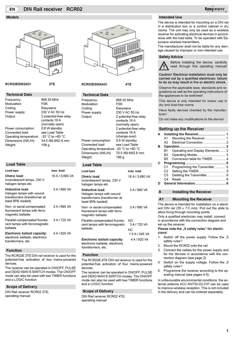
Eldat Easywave RCR02E5002A01 User manual

Eldat

Eldat Easywave RCR02E5002A01 User manual

Eldat EASY WAVE RCL03 User manual

Eldat

Eldat EASY WAVE RCL03 User manual

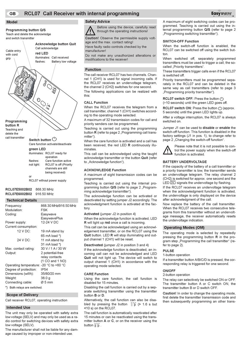
Eldat EasyWave RCL07 User manual

Eldat

Eldat EasyWave RCL07 User manual

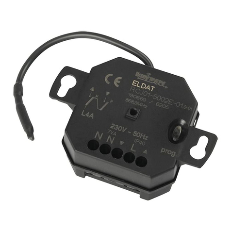
Eldat RCJ01 Series User manual

Eldat

Eldat RCJ01 Series User manual

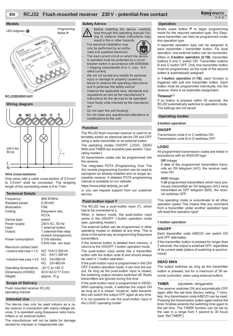
Eldat Easywave neo RCJ32 User manual

Eldat

Eldat Easywave neo RCJ32 User manual

Eldat RCJ31 User manual

Eldat

Eldat RCJ31 User manual

Eldat Easywave neo User manual

Eldat

Eldat Easywave neo User manual

Eldat RCL07 User manual

Eldat

Eldat RCL07 User manual

Eldat Easywave neo RCJ35 User manual

Eldat

Eldat Easywave neo RCJ35 User manual

Eldat Easywave RCL07 User manual

Eldat

Eldat Easywave RCL07 User manual

Eldat RCU01 Series User manual

Eldat

Eldat RCU01 Series User manual

Eldat RCU08 User manual

Eldat

Eldat RCU08 User manual

Eldat RCL03 Series User manual

Eldat

Eldat RCL03 Series User manual

Eldat Easywave RCL07 User manual

Eldat

Eldat Easywave RCL07 User manual

Eldat RCL03 Series User manual

Eldat

Eldat RCL03 Series User manual

Popular Receiver manuals by other brands

Williams Sound PPA R38 user manual

Williams Sound

Williams Sound PPA R38 user manual

AOR AR16 owner's manual

AOR

AOR AR16 owner's manual

Pioneer FH-M8527ZT-91 ES Service manual

Pioneer

Pioneer FH-M8527ZT-91 ES Service manual

Megasat HD 390 user manual

Megasat

Megasat HD 390 user manual

GRAUPNER 33575 operating instructions

GRAUPNER

GRAUPNER 33575 operating instructions

Vemco VR2AR user manual

Vemco

Vemco VR2AR user manual

Mpow BH100C user manual

Mpow

Mpow BH100C user manual

WAREMA EWFS Piccolo PL Operating and installation instructions

WAREMA

WAREMA EWFS Piccolo PL Operating and installation instructions

Yamaha RX-A700 owner's manual

Yamaha

Yamaha RX-A700 owner's manual

Harman Kardon AVR 7300 owner's manual

Harman Kardon

Harman Kardon AVR 7300 owner's manual

Integra DTR-80.1 instruction manual

Integra

Integra DTR-80.1 instruction manual

Samsung SIR-S60W owner's manual

Samsung

Samsung SIR-S60W owner's manual

Sony DIRECTV RECEIVER SAT-W60 installation guide

Sony

Sony DIRECTV RECEIVER SAT-W60 installation guide

LG HT302SD owner's manual

LG

LG HT302SD owner's manual

Xantech 780-80 installation instructions

Xantech

Xantech 780-80 installation instructions

Grundig DCR 1744 CO user manual

Grundig

Grundig DCR 1744 CO user manual

ACL SR-209 instruction manual

ACL

ACL SR-209 instruction manual

Integra DTR-5.1 Service manual

Integra

Integra DTR-5.1 Service manual

manuals.online logo
manuals.online logoBrands
  • About & Mission
  • Contact us
  • Privacy Policy
  • Terms and Conditions

Copyright 2025 Manuals.Online. All Rights Reserved.