Eldes ET082 User manual

GSM/GPRS COMMUNICATOR
ET082

Copyright ©“ELDES UAB”, 2012. All rights reserved.
It is strictly forbidden to copy and distribute information in this document or pass to a third party without an advanced written authorization from
“ELDES UAB”. “ELDES UAB” reserves the right to update or modify this document and/or related products without a warning. Hereby,„ELDES UAB“
declares that this GSM/GPRS communicator ET082 is in compliance with the essential requirements and other relevant provisions of Directive 1999/5/
EC. The declaration of conformity may be consulted at www.eldes.lt
User Manual v1.2
Safety instructions
Please read and follow these safety guidelines in order to maintain safety of operators and people around:
• GSM/GPRS communicator ET082 (further referenced as system, device or communicator) contains a radio transceiver operating
in GSM850/900/1800/1900 bands.
• DO NOT use the system where it can interfere with other devices and cause any potential danger.
• DO NOT use the system with medical devices if this is required in the manual of the medical device.
• DO NOT use the system in hazardous environment.
• DO NOT expose the system to high humidity, chemical environment or mechanical impacts.
• DO NOT attempt to personally repair the system.
• System labelling sticker is at the bottom of the device.
System ET082 is a device mounted in limited access areas. Any system repairs must be done only by qualied, safety aware
personnel.
Mains power must be disconnected before any installation or tuning work starts. The system installation or maintenance
must not be done during stormy conditions.
The system must be powered by main 10-24V 300mA power supply which must be approved by LST EN 60950-1 stan-
dard and be easily accessible.
Any additional devices linked to the system ET082 (computer, sensors, relays etc.) must be approved by LST EN 60950-1
standard.
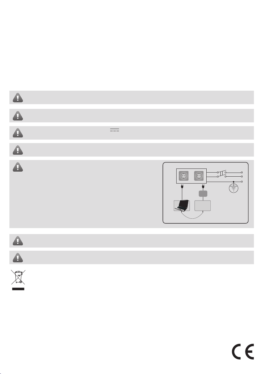
External power supply can be connected to AC mains only inside ins-
tallation room with automatic 2-pole circuit breaker capable of discon-
necting circuit in the event of short circuit or over-current condition.
Open circuit breaker must have a gap between connections of more
than 3mm and the disconnection current is 5A.
Fuse F1 model - miniSMDC 500mA. Blown fuse cannot be replaced by the user and the replacement fuses have to be exactly
the same as indicated by the manufacturer.
The device is fully turned o by disconnecting 2-pole switch o device of the external power supply or any other linked
device that the system ET082 is powered from.
The WEEE (Waste Electrical and Electronic Equipment) marking on this product (see left) or its documentation indicates that the pro-
duct must not be disposed of together with household waste. To prevent possible harm to human health and/or the environment, the
product must be disposed on in an approved and environmentally safe recycling process. For further information on how to dispose
of this product correctly, contact the system supplier, or the local authority responsible for waste disposal in your area.
Phase
AC 230V
50 Hz/DC 24V
USB cable
Null
ET082
PE

Limited Liability
The buyer must agree that the system will redu-
ce the risk of re, theft, burglary or other dangers
but does not guarantee against such events. “EL-
DES UAB” will not take any responsibility regarding
personal, property or revenue loss while using the
system. “ELDES UAB” responsibility according to
local laws does not exceed value of the purchased
system.“ELDES UAB”is not aliated with GSM ope-
rators providing cellular services, therefore is not
responsible for network services, coverage or its
operation.
Manufacturer Warranty
The system carries a 24-month warranty by the
manufacturer “ELDES UAB”.
Warranty period starts from the day the system
has been purchased by the end user. The warranty
is valid only if the system has been used as inten-
ded, following all guidelines listed in the manual
and within specied operating conditions. Receipt
with purchase date must be kept as a proof.
The warranty is voided if the system has been
exposed to mechanical impacts, chemicals, high
humidity, uids, corrosive and hazardous environ-
ment or other force majeure factors.
Package Content
1. ET082.......................................................................qty. 1
2. User manual..........................................................qty. 1
3. GSM antenna........................................................qty. 1
4. Jumpers..................................................................qty. 4
5. Plastic standos...................................................qty. 7
About User Manual
This document describes only basic operation
and installation of ET082 device. It is very impor-
tant to read the user manual before starting to use
the system.
Contents
1. General Information..................................................................... 4
1.1 Operation Description ..............................................................................4
2. Technical Specications............................................................... 6
2.1 Electrical & Mechanical Specications ..............................................6
2.2 Main Unit, Connector, Pin & LED Functionality .............................7
2.2.1 Main Unit Functionality................................................................7
2.2.2 Connector Functionality ..............................................................7
2.2.3 Pin Functionality .............................................................................7
2.2.4 LED Functionality............................................................................7
2.3 Connection Circuit ......................................................................................8
3. Installation.................................................................................... 9
4. Skyrelio pavadinimas................................................................. 10
4.1 PSTN Line and GSM Connection Status Monitoring.................... 10
4.2 Inputs & Оutputs.......................................................................................10
4.3 Remote Conguration of the Alarm System via DTMF ............... 10
5. Communication Modes & Methods...........................................11
5.1 Wiring Diagrams.....................................................................................11
5.1.1 No PSTN Connection..................................................................12
5.1.2 With PSTN Connection...............................................................12
5.1.3 With PSTN Connection through PBX.................................... 13
5.2 Basic Mode ............................................................................................... 13
5.2.1 Voice Calls Method...................................................................... 14
5.2.2 SMS Method ..................................................................................14
5.2.3 Voice Calls + SMS Method ........................................................ 15
5.2.4 GPRS Method ................................................................................16
5.3 Advanced Mode ..................................................................................... 17
5.3.1 Voice Calls Method...................................................................... 17
5.3.2 SMS Method ..................................................................................18
5.3.3 GPRS Method ................................................................................19
5.3.4 CSD Method ................................................................................. 20
6. Conguration & Control............................................................. 21
6.1 Ways of System Conguration ..........................................................21
6.2 Remote System Conguration via GPRS Connection ...............21
6.2.1 Establishing Remote Connection Between
ET082 System and Conguration Server........................22
6.2.2 Connecting to ELDES Conguration Server
using ELDES Conguration Tool Software..................... 22
6.2.3 Ending the Conguration Process.................................... 23
6.3 Conguration Parameter Set (SMS).................................................... 23
7. Technical Support.......................................................................27
7.1 Restoring Default Conguration .....................................................27
7.2 Upgrading Firmware............................................................................. 27
7.3 Technical Support.................................................................................. 27
8. Related products ..........................................................................28

4
1. General Information
Communicator ET082 is a device for transmitting data from alarm system to monitoring station via:
• PSTN (telephone landline);
• Voice Calls (GSM audio channel);
• Voice Calls (GSM audio channel) and/or to users via SMS message;
• GPRS network;
• CSD (fax line).
ET082 main applications & features:
• Property security;
• Data re-transmission to monitoring station via GSM/GPRS/CSD and/or to preset user via SMS;
• Backup connection for PSTN;
• PSTN status monitoring in case it is cut-o or disconnected;
• Alarm system remote conguration via DTMF.

User manUal elDes eT082 v1.2 5
2. Technical Specications
2.1 Electrical & Mechanical Specications
Power Supply 10-24V 300mA max
Peak Current Consumption 700 mA max.
Current Used in Standby Mode 120mA max
GSM Modem Frequency 850/900/1800/1900 MHz
Communications Voice Calls, SMS, GPRS, CSD
Supported Protocols Ademco Contact ID®, 4+2, Scancom, EGR100, Kronos, SIA IP
Maximum Number of Users Receiving
Alarm System Events by SMS Message
5
Maximum Number of Users for Input/Output Control 3
Number of “Low” Level (Negative) Digital Inputs 3
Allowable Input Values Voltage 0... 1.45V; current: 0.8... 0.6mA
Input Type NO (normally open)
Number of Outputs 3
Output C1 - C3 Circuit
Maximum Commuting Output Values Voltage: 30V ; current: 50 mA
Dimensions 130 x 73 mm
Operating temperature range -20...+55oC
Generated Phone Line Values Voltage: 18V; current: 25mA; impedance: 600Ω
Dial Tone Frequency of Generated Phone line 350 Hz
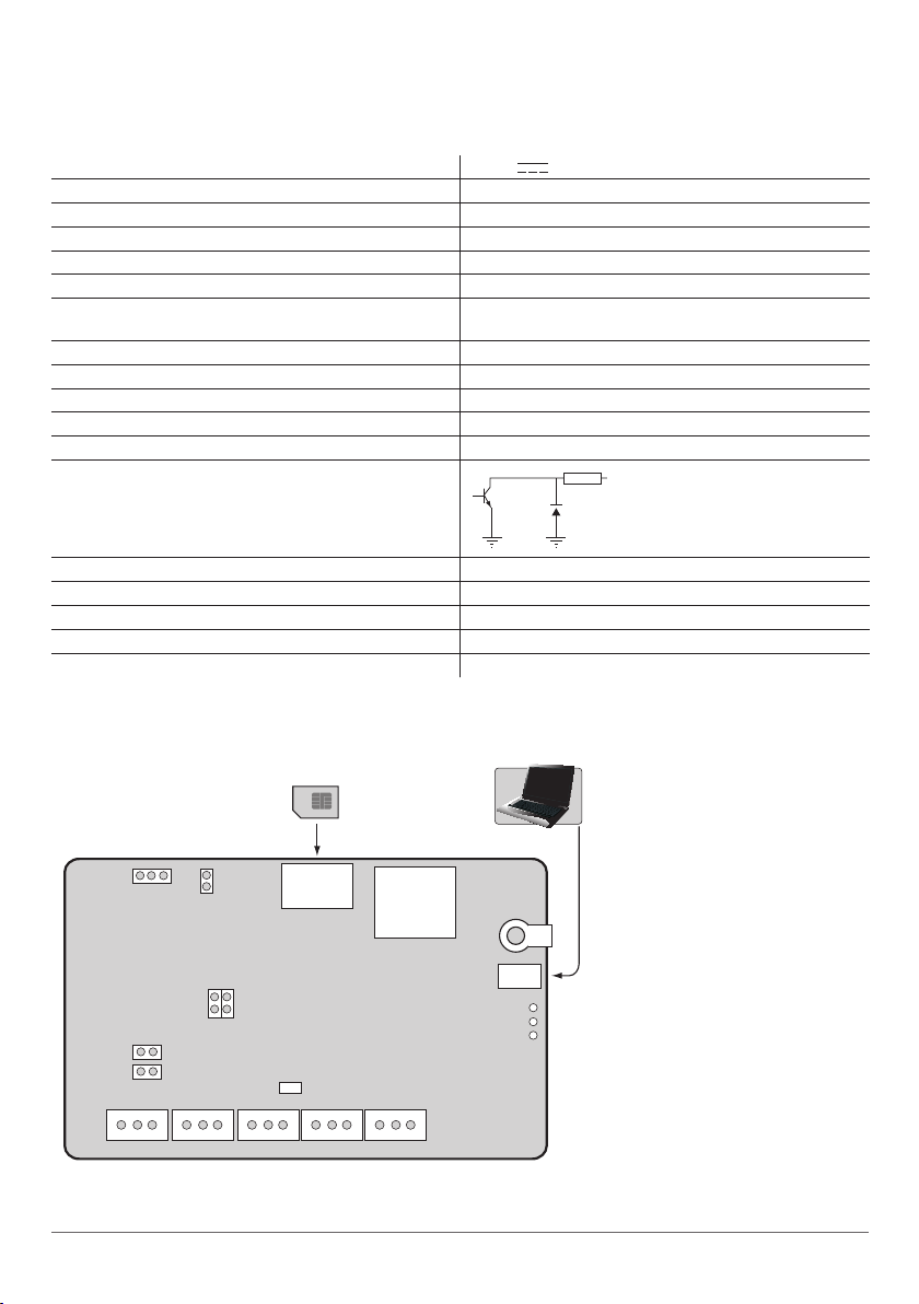
GSM
MODEM
INFO
STATUS
GSM
USB
DEF
F1
L1 L2 L3 L4 RING TIP Z1
C1 DC+ COM C2 Z2 COMC3 Z3
MODE
SET
JP9
UART
JP8
For configurations
SIM CARD
ANT
Fig. No 2
1 R OUT Open collector output.
Output is pulled to COM when
turned on.

6USER MANUAL ELDES ET082 V1.0 6
2.2 Main Unit, Connector, Pin & LED Functionality
2.2.1 Main Unit Functionality
GSM MODEM GSM network 850/900/1800/1900 MHz modem
SIM CARD SIM card slot / holder
ANT GSM antenna SMA type connector
F1 Fuse model – miniSMDC 500mA
USB Mini USB port
2.2.2 Connector Functionality
Labelling Description
L1 - L4 Landline or PBX contacts (according to backup mode)
RING RING contact
TIP TIP contact
C1 - C3 Outputs
DC+ Positive power supply contact
COM Negative power supply contact / Common contact
Z1 - Z3 Inputs
2.2.3 Pin Functionality
Labelling Description
DEF For restoring factory default settings
SET For communication method of Basic mode set up
MODE For communication method of Basic mode set up
JP8, JP9 For direct data transmission via PSTN with status monitoring
UART For retreiving debug log
2.2.4 LED Functionality
Labelling Description
INFO Operation activity status
STATUS Device status
GSM GSM network strength
GSM Signal Strength Indication
GSM signal strength is indicated by GSM LED. To ensure the best quality of the network adjust the position of GSM antenna and
nd the strongest possible signal by observing the GSM LED indications.
GSM LED Indication GSM Signal Strength
O No connection
Flashing every 3 seconds The connection is not reliable
Flashing every 1 second Satisfactory
Flashing several times per second Good
On Excellent

Device Activity Indication
STATUS LED Indication Description
O No power supply or some fault is present
Flashing several times per second SIM card is not inserted / insterted improperly
On Device is operating and ready for use
Working Mode Indication
INFO LED Indication Description
O Device is in standby mode
Flashing several times
per second
Device retransmits the data sent from alarm system to the monitoring station (this
indication is possible when device is operating in communication mode 1)
On Device is decoding data to user-understandable text format.
2.3 Connection Circuit
COM connectors of ET082 and alarm system unit must be connected.
ET082 inputs Z1 - Z3 are connected to PGM outputs of alarm system unit if PGM output is
implemented as open collector circuit or any other circuit and if it commutes with COM. It is
also possible to connect motion sensor or any other sensor to ET082 Z1 - Z3 inputs.
ET082 C1 - C3 outputs can be connected to the input of electrical appliances if it commutes
with COM. This connection allows to control heating, lighting, gates, blinds, water pump etc.
ET082
Alarm system
or other appliance
+12V
PGM
CxDC+ COM
Zx
ATTENTION: Before connecting ET082 power supply to alarm system's auxiliary
output (AUX), please, make sure that the output is able to maintain peak curent
consumption of up to 700mA max. Otherwise, please, use an external power sup-
ply for ET082.
Fig. No 3

8
3. Installation
The system can be installed in a metal or non-ammable plastic enclosure together with alarm system unti. When the metal en-
closure is used it is necessary to ground the enclosure using yellow/green colour cable. For the connection use 0.50 mm21 thread
cable. For the device connection to input/output connectors use 0.50 mm21 thread cable of up to 100 meters length.
1. Place the SIM card into the card holder and make sure that PIN code request is disabled. The PIN code can be disabled by
inserting the SIM card into a mobile phone and following proper menu steps. There must be no SMS messages stored in
the memory.
ATTENTION: The system is NOT compatible with pure 3G SIM cards. Only 2G SIM cards and 3G SIM cards with 2G prole
enabled are supported. For more details, please, contact your GSM operator.
2. Connect the GSM antenna to SMA connector. It is not recommended to turn on the device without GSM antenna connec-
ted.
NOTE: It is recommended to install the GSM antenna away from the alarm system to ensure better quality of the audio
signal. It is not recommend to install the antenna inside the metal enclosure.
3. Connect the circuit according to desired communication method. For more details, please, refer to chapters 2.3 Con-
nection Circuit & 5.1 Wiring Diagrams
4. The system should start in less than a minute. GSM LED indicator should be blinking or be ON indicating successful con-
nection to GSM network.
NOTE: It is highly recommended to choose the same GSM cellular provider both for users and for ET082 communicator in
order to assure fast and reliable SMS message delivery and phone call connection.
NOTE: To ensure maximum system operation reliability we recommend not to use pay-as-you-go SIM cards. If the balance is
insucient the system will not be able to inform users by SMS or send data messages.
IMPORTANT: Power supply at alarm system must be disconnected before any installation or tuning work.

User manUal elDes eT082 v1.2 9
For more details, please refer to chapter 5. Communication Methods & Modes.
4. Operation Description
ET082 communicator is a GSM/GPRS device transmitting data from alarm system to monitoring station and/or preset user phone
number. The following diagram indicates communication modes & methods supported by the device:
USING PSTN?
YES
Basic Advanced
NO / PSTN is cut-o
Voice CallsContact ID
Contact ID
Contact ID
Contact ID
Contact ID
Contact ID
Contact ID
Contact ID
Contact ID
Scancom
Scancom
Scancom
Kronos
Kronos
Kronos
Kronos
EGR100
EGR100
EGR100
EGR100
SIA IP
SIA IP
SIA IP
SIA IP
Primary
Voice Calls
Voice Calls
Voice Calls
SMS
SMS
SMS
GPRS 1... 3
GPRS 1... 3
GPRS 1... 3
CSD
CSD
CSD
N/A
N/A
Backup 1
Backup 2
SMS
Voice Calls + SMS
GPRSGPRS 1
Direct data transmission to monitoring station
Set by PCB jumper
combination
Direct channel
Converted to user-
understandable text
Converted to
user-understandable text
Converted to
user-understandable text
Converted to
user-understandable text
By SMS: converted to
user-understandable text
Direct channel
Data buering
Data buering
Data buering
Set by ELDES Conguration Tool
Communication method?
PSTN line is being monitored by ET082 in
case it is cut-o

10
4.1 PSTN Line and GSM Connection Status Monitoring
The device can also be used for direct data transmission from alarm system to monitoring station via PSTN. This feature allows to
monitor the PSTN status and notitify monitoring station and/or preset user in case of PSTN loss/restore events. Depending on the
set up communication method and conguration, ET082 can notify by:
• sending an SMS message to a preset user (SMS method);
• transmitting a data message to monitoring station via GSM audio channel (Voice Calls method);
• transmitting a data message to monitoring station via GPRS netowrk (GPRS method);
• transmitting a data message to monitoring station via fax line (CSD method).
In case of PSTN failures, the communicator switches to the set up communication method and backs up PSTN until it is restored.
In addition, the PSTN loss/restore event can also be indicated by SMS message sent to up to 3 preset users or by any output of
ET082 device.
In case of PSTN or GSM connection failure, the device can turn the output (-s) ON and turn it OFF after the PSTN or GSM is restored.
For more details, please refer to ELDES Conguration Tool software‘s HELP section.
ET082 can also detect temporary service suspension by the service provider for technical or billing reasons even if a dial tone is still
present as“busy” tone. This feature requires an additional audio module which must be requested in advance.
4.2 Inputs & Оutputs
ET082 communicator has 3 built-in digital inputs (NO - normally open) for connection to PGM outputs of alarm system or any
sensor connection, In case of input alarm/restore event, the communicator sends an SMS message to up to 3 preset user (-s).
Built-in open collector outputs allow to connect and control up to 3 electrical appliances. The outputs can be controlled either
by SMS message from user who knows the correct SMS password, either automatically in case of PSTN or GSM connection loss/
restore event. The outputs can provide control over heating, lighting, gates, blinds etc.
For more details, please, refer to ELDES Conguration Tool software‘s HELP section.
4.3 Remote Conguration of the Alarm System via DTMF
ET082 supports a two-way communication providing a possibility for alarm system remote conguration via DTMF. DTMF dialing
mode must be supported and enabled in alarm system.

User manUal elDes eT082 v1.2 11
5. Communication Modes & Methods
ET082 communicator supports Basic and Advanced modes & methods providing a variety of communication protocols. Basic mode
is recommended when only one communication method is required while Advanced mode is recommended to use when one or
more backup communication methods are required. Please note, that some protocols are not supported in Basic mode and vice
versa.
COMMUNICATION MODES & METHODS
Basic Mode Advanced Mode
Method Protocol Method Protocol
Voice Calls (GSM audio - direct
channel) Ademco Contact ID®, 4+2 Voice Calls (GSM audio - data
buering)
Ademco Contact ID®,
Scancom
SMS (up to 5 users)*
Ademco Contact ID®
(converted to user-
understandable text)
SMS (up to 5 users)*
Ademco Contact ID®
(converted to user-
understandable text)
GPRS (1 destination IP address) EGR100, Kronos, SIA IP GPRS (up to 3 destination IP
addresses) EGR100, Kronos, SIA IP
Voice Calls (GSM audio - direct
channel) + SMS (up to 5 users)*
Ademco Contact ID® (by
SMS: converted to user-
understandable text)
CSD (fax line)
* SMS messages are sent to the preset user phone number (-s) set in ELDES Conguration Tool software.
5.1 Wiring Diagrams
ATTENTION: Before connecting ET082 power supply to alarm system‘s auxiliary output (AUX), please, make sure that the
output is able to maintain peak curent consumption of up to 700mA max. Otherwise, please, use an external power supply
for ET082.
Before conguring communication methods, the user must decide whether direct data transmission from alarm system to mo-
nitoring station via PSTN and PSTN status monitoring is required or not. This is dened by a respective circuit wiring and jumper
presence on JP8/JP9 PCB pins.
NOTE: PSTN is always a primary (master) connection and it cannot be set as backup when used.

12
5.1.1 No PSTN Connection
With this wiring the communicator retransmits data from alarm system to monitoring station by the selected communication
method.
1. Connect the circuit as indicated in Fig. No. 4– connect telephone contacts of the alarm system RING/TIP to RING/TIP
contacts of the communicator.
2. Connect power supply to DC+/COM contacts. Power supply is usually used as AUX- and AUX+ output of alarm system.
3. NO jumpers have to be set on JP8/JP9 pins.
5.1.2 With PSTN Connection
With this wiring the communicator retransmits data from alarm system to monitoring station via landline (PSTN).
1. Connect the circuit as indicated in Fig. No. 5 – connect telephone contacts of the alarm system RING/TIP to RING/TIP
contacts of communicator.
2. Connect L3/L4 contacts to landline (PSTN).
3. Connect power supply to DC+/COM contacts. Power supply is usually used as AUX- and AUX+ output of alarm system.
4. Set the jumpers on JP8 and JP9 pins.
L1 L2 L3 L4 RING TIP C1 DC+ COM C2 Z2 Z1 C3 Z3 COM
AUX+ AUX-
ALARM SYSTEM
RING/TIP
Fig. No 4
JP8 JP9
JP8 JP9
ALARM SYSTEM
L1 L2 L3 L4 RING
To landline
(PSTN)
TIP DC+ COMC1
AUX+ AUX-
RING/TIP
C2 Z2 Z1 C3 Z3 COM
Fig. No 5

User manUal elDes eT082 v1.2 13
5.1.3 With PSTN Connection through PBX
With this wiring the communicator retransmits data from alarm system to monitoring station via landline (PSTN) through private
branch exchange station (PBX).
1. Connect the circuit as indicated in Fig. No. 6 – connect telephone contacts of the alarm system RING/TIP to RING/TIP
contacts of communicator.
2. Connect L1/L2 contacts to external landline (PSTN).
3. Connect L3/L4 contacts to internal landline (PSTN) of PBX.
4. Connect power supply to DC+/COM contacts. Power supply is usually used as AUX- and AUX+ output of alarm system.
5. NO jumpers have to be set on JP8/JP9 pins.
5.2 Basic Mode
The communication method of Basic mode is selected by jumper position on SET/MODE PCB pins. Basic mode features the follo-
wing communication methods:
• Voice Calls;
• SMS;
• Voice Calls + SMS;
• GPRS.
NOTE: The jumper position on SET/MODE PCB pins becomes ineective as soon as Advanced mode is enabled.
ALARM SYSTEM
L1 L2 L3 L4
RING
To external
landline (PSTN)
To internal
landline (PSTN)
TIP
RING TIP DC+ COMC1
AUX+ AUX-
PBX
C2 Z2 Z1 C3 Z3 COM
Fig. No 6
FOR ADVANCED USERS ONLY!
JP8 JP9

14
5.2.1 Voice Calls Method
ATTENTION: DTMF phone number dialing mode must be enabled on alarm system, activated Ademco Contact ID® or 4+2 data
transmission protocol and monitoring station phone number set with international code, i.e. For UK London 20xxxxxxxx or
004420xxxxxxxx. The plus character is not allowed.
By this method the communicator receives Ademco Contact ID® or 4+2 protocol data sent from alarm system and transmits it to
monitoring station via GSM audio – direct channel.
NO jumpers have to be set on SET/MODE pins in order to select Voice Calls method. See Fig. No. 7.
If PSTN connection is used, the communicator also monitors the voltage (dial tone monitoring optional) on the PSTN and in case
the PSTN is unavailable, disconnected or cut o (voltage drops below 4V), ET082:
• switches to Voice Calls method,
• noties monitoring station about PSTN failure,
• continues transmitting data to monitoring station via GSM audio – direct chanel until the PSTN is restored.
NOTE: By default, notication about PSTN loss/restore is disabled and has to be enabled if required using ELDES Conguration
Tool software. For more details, please, refer to software’s HELP section.
5.2.2 SMS Method
ATTENTION: It is necessary to set monitoring station phone number on alarm system for SMS method. In such case you can
use any number (one digit is enough).
By this method the communicator receives Ademco Contact ID® protocol data sent from alarm system and converts it to user-un-
derstandable text which is sent to preset user (-s) by SMS message.
1. Set the jumper on MODE pins in order to select SMS method. See Fig. No. 8.
2. Add user phone number (-s) to the communicator using ELDES Conguration Tool software.
3. Congure Ademco Contact ID® data message structure using ELDES Conguration Tool software if required.
For more details, please, refer to ELDES Conguration Tool software’s HELP section.
If PSTN connection is used, the communicator also monitors the voltage (dial tone monitoring optional) on the PSTN and in case
the PSTN is unavailable, disconnected or cut o (voltage drops below 4V), ET082:
• switches to SMS method,
• noties the preset user (-s) by SMS message about PSTN failure,
• continues sending the converted Ademco Contact ID® by SMS message to preset user (-s) until the PSTN is restored.
NOTE: By default, notication about PSTN loss/restore is disabled and has to be enabled if required using ELDES Conguration
Tool software. For more details, please, refer to software’s HELP section.
Fig. No 7
Fig. No 8

User manUal elDes eT082 v1.2 15
5.2.3 Voice Calls + SMS Method
ATTENTION: DTMF phone number dialing mode must be enabled on alarm system, activated Ademco Contact ID® data
transmission protocol and monitoring station phone number set with international code, i.e. For UK London 20xxxxxxxx or
004420xxxxxxxx. The plus character is not allowed.
By this method the communicator receives Ademco Contact ID® protocol data sent from alarm system and transmits it to monito-
ring station via GSM audio – direct channel. In addition, the data is converted to user-understandable text which is sent to preset
user (-s) by SMS message.
1. Set the jumper on SET pins in order to select Voice Calls + SMS method. See Fig. No. 9.
2. Add user phone number (-s) to the communicator using ELDES Conguration Tool software.
3. Congure Ademco Contact ID® data message structure using ELDES Conguration Tool software if required .
For more details, please, refer to ELDES Conguration Tool software’s HELP section.
If PSTN connection is used, the communicator also monitors the voltage (dial tone monitoring optional) on the PSTN and in case
the PSTN is unavailable, disconnected or cut o (voltage drops below 4V), ET082:
• switches to Voice Calls + SMS method,
• noties monitoring station about PSTN failure,
• noties the preset user (-s) by SMS message about PSTN failure,
• continues transmitting data to monitoring station via GSM audio – direct channel until the PSTN is restored,
• duplicates and converts data and sends it to preset user (-s) by SMS message until the PSTN is restored.
NOTE: By default, notication about PSTN loss/restore is disabled and has to be enabled if required using ELDES Conguration
Tool software. For more details, please, refer to software’s HELP section.
Fig. No 9

16
5.2.4 GPRS Method
ATTENTION: It is necessary to set monitoring station phone number on alarm system for GPRS method. In such case you can
use any number (one digit is enough).
By this method the communicator receives Ademco Contact ID® protocol data sent from alarm system, converts it to EGR100, Kronos
or SIA IP protocol data message and transmits it to monitoring station via GPRS network.
1. Set the jumper on SET and MODE pins in order to select GPRS method. See Fig. No. 10.
2. Set the following ET082 GPRS 1 section parameters using ELDES Conguration Tool software:
• APN – Access-point-name provided by GSM operator;
• User Name – User name provided by GSM operator;
• Password – Password provided by GSM operator;
• Server IP – Public IP address of the computer (router) running Kronos/EGR100 software.
• Port – Forwarded TCP/UDP port number for the computer running Kronos/EGR100 software.
• Protocol – Format of the data message transmitted from ET082 to monitoring station by GPRS method. Available protocols:
• Kronos – Kronos LT/Kronos NET monitoring station software data format;
• EGR100 – EGR100 GPRS software data format;
• SIA IP – SIA/IP data format complying with ANSI/SIA DC-09-2007 standard.
3. Set the following parameters in EGR100 software:
• TCP/UDP Server Port - Forwarded port for communication with the device via GPRS connection.
NOTE: Port must be set the same both on the communicator using ELDES Conguration Tool and in EGR100 software.
For more details, please, refer to EGR100 or Kronos LT/Kronos NET and ELDES Conguration Tool software’s HELP section for more
details.
If PSTN connection is used, the communicator also monitors the voltage (dial tone monitoring optional) on the PSTN and in case
the PSTN is unavailable, disconnected or cut o (voltage drops below 4V), ET082:
• switches to GPRS 1... 3 method,
• noties monitoring station about PSTN failure,
• continues transmitting data to monitoring station via GPRS network until the PSTN is restored.
Fig. No 10
NOTE: By default, notication about PSTN loss/restore is disabled and has to be enabled if required using ELDES Conguration
Tool software. For more details, please, refer to software’s HELP section.

User manUal elDes eT082 v1.2 17
5.3 Advanced Mode
The communication method (-s) of Advanced mode is selected by ELDES Conguration Tool. Advanced mode features the following
communication methods:
• Voice Calls;
• SMS;
• GPRS;
• CSD.
Advanced mode supports 1 primary and up to 2 backup connections. All of the aforementioned communication methods can be
set up as primary or backup in any sequence order.
NOTE: The jumper position on SET/MODE PCB pins becomes ineective as soon as Advanced mode is enabled.
5.3.1 Voice Calls Method
ATTENTION: DTMF phone number dialing mode must be enabled on alarm system, activated Ademco Contact ID® or Scancom
data transmission protocol and monitoring station phone number set with international code, i.e. For UK London 20xxxxxxxx
or 004420xxxxxxxx. The plus character is not allowed.
By this method the communicator receives Ademco Contact ID® or Scancom protocol data sent from alarm system, saves it to me-
mory buer and transmits it to monitoring station via GSM audio channel.
Set the following ET082 parameters using ELDES Conguration Tool software:
1. Switch to Advanced mode by enabling Backup Enabled parameter.
2. Select Voice Calls method as Primary connection.
3. Set Backup 1 and Backup 2 connections if required.
4. Select Contact ID or Scancom protocol. By default, Contact ID is selected.
For more details, please, refer to ELDES Conguration Tool software’s HELP section.
If PSTN connection is used, the communicator also monitors the voltage (dial tone monitoring optional) on the PSTN and in case
the PSTN is unavailable, disconnected or cut o (voltage drops below 4V), ET082:
• switches to Voice Calls method,
• noties monitoring station about PSTN failure,
• continues transmitting data to monitoring station via GSM audio channel with data buering until the PSTN is restored.
NOTE: In case of Voice Calls method failure the communicator switches to Backup 1 and Backup 2 connections (if set) respecti-
vely and attempts to continue transmitting data to monitoring station until the previous connection (-s) is restored.

18
5.3.2 SMS Method
ATTENTION: It is necessary to set monitoring station phone number on alarm system for SMS method. In such case you can
use any number (one digit is enough).
By this method the communicator receives Ademco Contact ID® protocol data sent from alarm system and converts it to user-un-
derstandable text which is sent to preset user (-s) by SMS message.
Set the following ET082 parameters using ELDES Conguration Tool software:
1. Switch to Advanced mode by enabling Backup Enabled parameter.
2. Select SMS method as Primary connection.
3. Set Backup 1 and Backup 2 connections if required.
4.. Add user phone number (-s).
5. Congure Ademco Contact ID® data message structure if required.
For more details, please, refer to ELDES Conguration Tool software’s HELP section.
If PSTN connection is used, the communicator also monitors the voltage (dial tone monitoring optional) on the PSTN and in case
the PSTN is unavailable, disconnected or cut o (voltage drops below 4V), ET082:
• switches to SMS method,
• noties the preset user (-s) by SMS message about PSTN failure,
• continues sending the converted Ademco Contact ID® by SMS message to preset user (-s) until the PSTN is restored.
NOTE: In case of SMS method failure the communicator switches to Backup 1 and Backup 2 connections (if set) respectively and
attempts to continue transmitting data to monitoring station until the previous connection (-s) is restored.

User manUal elDes eT082 v1.2 19
5.3.3 GPRS Method
ATTENTION: It is necessary to set monitoring station phone number on alarm system for GPRS method. In such case you can
use any number (one digit is enough).
NOTE: GPRS method of Advanced mode supports up to 3 dierent monitoring station server IP addresses for backup purposes.
The IP addresses are set in GPRS 1... GPRS 3 sections respectively.
By this method the communicator receives Ademco Contact ID® protocol data sent from alarm system, converts it to EGR100, Kronos
or SIA IP protocol data message and transmits it to monitoring station via GPRS network.
Set the following ET082 parameters using ELDES Conguration Tool software:
1. Switch to Advanced mode by enabling Backup Enabled parameter.
2. Select GPRS 1... 3 method as Primary connection.
3. Set Backup 1 and Backup 2 connections if required.
4. Set the following GPRS 1... GPRS 3 section parameters referring to GPRS 1... 3 method selected respectively in steps 2 and 3:
• APN – Access-point-name provided by GSM operator;
• User Name – User name provided by GSM operator;
• Password – Password provided by GSM operator;
• Server IP – Public IP address of the computer (router) running Kronos/EGR100 software.
• Port – Forwarded TCP/UDP port number for the computer running Kronos/EGR100 software.
• Protocol – Format of the data message transmitted from ET082 to monitoring station by GPRS method. Available pro-
tocols:
• Kronos – Kronos LT/Kronos NET monitoring station software data format;
• EGR100 – EGR100 GPRS software data format;
• SIA IP – SIA/IP data format complying with ANSI/SIA DC-09-2007 standard.
5. Set the following parameters in EGR100 software:
• TCP/UDP Server Port - Forwarded port for communication with the device via GPRS connection.
NOTE: Port must be set the same both on the communicator using ELDES Conguration Tool and in EGR100 software.
For more details, please, refer to EGR100 or Kronos LT/Kronos NET and ELDES Conguration Tool software’s HELP section for more
details.
If PSTN connection is used, the communicator also monitors the voltage (dial tone monitoring optional) on the PSTN and in case
the PSTN is unavailable, disconnected or cut o (voltage drops below 4V), ET082:
• switches to GPRS 1... 3 method,
• noties monitoring station about PSTN failure,
• continues transmitting data to monitoring station via GPRS network until the PSTN is restored.
NOTE: In case of GPRS method failure the communicator switches to Backup 1 and Backup 2 connections (if set) respectively
and attempts to continue transmitting data to monitoring station until the previous connection (-s) is restored.

20
5.3.4 CSD Method
ATTENTION: It is necessary to set monitoring station phone number on alarm system for CSD method. In such case you can
use any number (one digit is enough).
By this method the communicator receives Ademco Contact ID® protocol data sent from alarm system, converts it to CSD protocol
data message and transmits it to monitoring station via CSD connection.
Set the following ET082 parameters using ELDES Conguration Tool software:
1. Switch to Advanced mode by enabling Backup Enabled parameter.
2. Select CSD method as Primary connection.
3. Set Backup 1 and Backup 2 connections if required.
4.. Set CSD monitoring station phone number.
For more details, please, refer to ELDES Conguration Tool software’s HELP section.
If PSTN connection is used, the communicator also monitors the voltage (dial tone monitoring optional) on the PSTN and in case
the PSTN is unavailable, disconnected or cut o (voltage drops below 4V), ET082:
• switches to CSD method,
• noties monitoring station about PSTN failure,
• continues transmitting data to monitoring station via CSD connection until the PSTN is restored.
NOTE: In case of CSD method failure the communicator switches to Backup 1 and Backup 2 connections (if set) respectively and
attempts to continue transmitting data to monitoring station until the previous connection (-s) is restored.
Other manuals for ET082
1
Table of contents
Other Eldes Cell Phone manuals