Eldes ET083 User manual
2G/3G COMMUNICATOR
ET083
EN

2
EN ET083 2G/3G COMMUNICATOR V1.0
User Manual v1.0
Valid for ET083 v01.00.00 and up
SAFETY INSTRUCTIONS
Please read and follow these safety guidelines to safeguard yourself and others:
• 2G/3G communicator ET083 (later referred to as “the device” or “the communicator”) contains a built-in radio transceiver operaing in the
following bands: EU-band model: 2G 900/1800MHz, 3G 900/2100MHz bands; US-band model: 2G 850/1900MHz, 3G 850/1900MHz; Muli-
band model: 2G 850/900/1800/1900MHz, 3G 800/850/900/1900/2100MHz
• DO NOT use the device where it can cause potenial danger and interfere with other devices – such as medical devices.
• DO NOT use the device in hazardous environment.
• DO NOT expose the device to high humidity, chemical environment or mechanical impact.
• DO NOT atempt to repair the device yourself – any repairs must be carried out by fully qualiied personnel only.
Please, use the 10-24V 300 mA DC power supply unit that meets the EN 60950-1 standard. Any addiional device you connect to
the device, such as a computer, must also be powered by an EN 60950-1 approved supply. When connecing the power supply to the
device, mind the polarity terminals. DO NOT switch the polarity terminals places.
External power supply can be connected to AC mains only inside installaion room with
automaic 2-pole circuit breaker capable of disconnecing circuit in the event of short circuit
or over-current condiion. Open circuit breaker must have a gap between connecions of
more than 3mm (0.12in) and the disconnecion current 5A.
Phase
AC 230V
50 Hz/DC 24V
USB cable
Null
PE
ET083
AC/DC
Disconnect the mains power before installing. Never install or carry out maintenance during stormy weather. The electric socket that
powers the device must be easily accessible.
To switch the device of, unplug the external electric power supply or any other linked equipment that the device is powered from.
A blown fuse cannot be replaced by the user. The replacement fuse has to be of the kind indicated by the manufacturer (fuse F1
model – MINISMDC050F 0.5A).
If you use a computer for the device coniguraion, it must be earthed.

3
EN
ET083 2G/3G COMMUNICATOR V1.0
Contents
1. GENERAL INFORMATION ...................................................................................................................................................................6
2. TECHNICAL SPECIFICATIONS.............................................................................................................................................................6
2.1. Electrical and Mechanical Characterisics ......................................................................................................................................................................... 6
2.2. Main Unit, LED Indicator and Connector Funcionality................................................................................................................................................... 7
2.3. LED Indicator Funcionality ................................................................................................................................................................................................... 7
2.4. Wiring Diagrams ....................................................................................................................................................................................................................... 8
3. INSTALLATION ....................................................................................................................................................................................9
4. GENERAL OPERATIONAL DESCRIPTION.......................................................................................................................................... 10
5. CONFIGURATION METHODS .............................................................................................................................................................. 11
5.1. SMS Text Messages ................................................................................................................................................................................................................. 11
5.2. ELDES Coniguraion Tool Sotware.................................................................................................................................................................................... 11
6. COMMUNICATION WIRING METHODS ...............................................................................................................................................13
6.1. RING/TIP Interface ..................................................................................................................................................................................................................13
6.2. Keybus and Serial Interfaces.................................................................................................................................................................................................15
7. COMMUNICATION MODES AND METHODS....................................................................................................................................... 16
7.1. Basic Mode.................................................................................................................................................................................................................................17
7.2. Advanced Mode........................................................................................................................................................................................................................21
8. 2G/3G MODEM SETTINGS.................................................................................................................................................................24
9. SMS FORWARD..................................................................................................................................................................................24
10. MONITORING STATION PHONE NUMBER AND ACCOUNT REPLACEMENT.....................................................................................25
11. SMS PASSWORD................................................................................................................................................................................25
12. USER PHONE NUMBERS....................................................................................................................................................................25
13. INPUTS...............................................................................................................................................................................................26
14. OUTPUTS ...........................................................................................................................................................................................28
14.1. Output Names .........................................................................................................................................................................................................................28
14.2.Output Control by SMS Text Message...............................................................................................................................................................................28
14.3.Output Control by Event .......................................................................................................................................................................................................29
15. TAMPERS............................................................................................................................................................................................31
16. PSTN CONNECTION STATE SUPERVISION ........................................................................................................................................31
17. 2G/3G CONNECTION STATE SUPERVISION.......................................................................................................................................31
18. PERIODIC DATA LINK STATE SUPERVISION .....................................................................................................................................32
19. ADVANCED KISSOFF MODE..............................................................................................................................................................32
20. DATE AND TIME.................................................................................................................................................................................33
21. PERIODIC TEST..................................................................................................................................................................................34
22. AUTOMATIC RESTART ......................................................................................................................................................................34
23. EVENTS LOG......................................................................................................................................................................................34
24. TECHNICAL SUPPORT.......................................................................................................................................................................35
24.1. Troubleshooing......................................................................................................................................................................................................................35
24.2. Restoring Default Parameters ...........................................................................................................................................................................................35
24.3. Updaing the Firmware via USB Cable ............................................................................................................................................................................35
24.4. Updaing the Firmware Remotely.....................................................................................................................................................................................36
25. RELATED PRODUCTS ........................................................................................................................................................................37

4
EN ET083 2G/3G COMMUNICATOR V1.0
TERMS OF USE
The following terms and condiions govern use of the ET083 device and contains important informaion on limitaions regarding the product’s use and
funcion, as well as informaion on the limitaions of the manufacturer’s liability. Please carefully read these terms and condiions. For more informaion
on your product, please visit eldesalarms.com
TECHNICAL SUPPORT
In order to ensure coninuous and proper operaion of the ET083 device and uninterrupted service, it is the responsibility of the User to make sure that:
(i) the product is properly installed, and (ii) there is constant internet or 2G/3G connecion and electrical supply (low batery must be replaced in ime).
If you experience diiculty during the installaion or subsequent use of the system, you may contact ELDES, UAB distributor or dealer in your country/
region. For more informaion see eldesalarms.com
WARRANTY PROCEDURES
Warranty and out of warranty service should be obtained by contacing the system integrator/dealer/retailer/e-tailer or distributor where the customer
purchased the product. When requesing for service, the proof of purchase and the product serial number must be provided. The return of the defecive
product should be strictly through the original route of purchase, and the customers shall pack the product appropriately to prevent the returned product
from sufering in the transportaion.
MANUFACTURER WARRANTY
ELDES provides a limited warranty for its products only to the person or enity that originally purchased the product from ELDES or its authorized dis-
tributor or retailer and only in case of defecive workmanship and materials under normal use of the system for a period of twenty four (24) months from
the date of shipment by the ELDES, UAB (Warranty Period). Warranty obligaions do not cover expandable materials (power elements and/or bateries),
holders and enclosures. The warranty remains valid only if the system is used as intended, following all guidelines outlined in this manual and in accord-
ance with the operaing condiions speciied. The warranty is void if the system has been exposed to mechanical impact, chemicals, high humidity, luids,
corrosive and hazardous environments or force majeure factors.
If a hardware defect arises and a valid claim is received within the Warranty Period, at its own discreion, ELDES, UAB will either (a) repair a hardware
defect at no charge, using new or refurbished replacement parts, or (b) exchange the product with a product that is new or which has been manufactured
from new or serviceable used parts and is at least funcionally equivalent to the original product, or (c) refund the purchase price of the product.
LIMITED LIABILITY
The buyer must agree that the system will reduce the risk thet, burglary or other dangers but does not provide guarantee against such events. ELDES,
UAB will not assume any responsibility regarding personal or property, or revenue loss while using the system. ELDES, UAB is not ailiated with any of
the Internet providers, therefore, it shall not responsible for the quality of Internet service.
ELDES, UAB shall also assume no liability due to direct or indirect damage or loss, as well as unreceived income when using the system, including cases,
when the damages arise due to the above menioned risks, when due to breakdown or malfuncion the user is not informed in a imely manner about a
risk which has arisen. In any case, the liability of ELDES, UAB, as much as it is allowed by the laws in force, shall not exceed the price of acquisiion of the
product.
CONSUMER PROTECTION LAWS
FOR CONSUMERS WHO ARE COVERED BY CONSUMER PROTECTION LAWS OR REGULATIONS IN THEIR COUNTRY OF PURCHASE OR, IF DIFFER-
ENT, THEIR COUNTRY OF RESIDENCE, THE BENEFITS CONFERRED BY THIS WARRANTY ARE IN ADDITION TO ALL RIGHTS AND REMEDIES
CONVEYED BY SUCH CONSUMER PROTECTION LAWS AND REGULATIONS. This warranty grants upon you speciic legal rights, and you may also
have other rights that vary by country, state or province.
DISPOSAL AND RECYCLING INFORMATION
The WEEE (Waste Electrical and Electronic Equipment) marking on this product (see left) or its documentation indicates that the
product must not be disposed of together with household waste. To prevent possible harm to human health and/or the environ-
ment, the product must be disposed on in an approved and environmentally safe recycling process. For further information on how
to dispose of this product correctly, contact the system supplier, or the local authority responsible for waste disposal in your area.
Dear Customer,
Thank you for choosing to purchase the 2G/3G communicator ET083. Your thoughtful decision will ensure reliable soluion for many years
as all ELDES products are manufactured to meet the highest standards.
We are conident that you will be completely saisied with your product. However, in the unlikely event that you do experience a problem,
please contact the dealer from whom you made your purchase.
ELDES UAB
eldesalarms.com

5
EN
ET083 2G/3G COMMUNICATOR V1.0
Contents of Pack Not included
1 x
1 x
1 x
SIM card – we
recommend you
get a contract
SIM, not Pay As
You Go.
miniUSB cable –
can be obtained
from your local
distributor.
It is strictly forbidden to copy and distribute informaion in this document or pass to a third party without an advanced writen au-
thorizaion from ELDES UAB. ELDES UAB reserves the right to update or modify this document and/or related products without a
warning. Hereby, ELDES UAB declares that the 2G/3G communicator ET083 is in compliance with the essenial requirements and
other relevant provisions of Direcive 1999/5/EC. The declaraion of conformity may be consulted at eldesalarms.com
Copyright © ELDES UAB, 2016. All rights reserved

6
EN ET083 2G/3G COMMUNICATOR V1.0
1. GENERAL INFORMATION
ET083 is a micro-controller based device intended to replace the third-party PSTN/non-2G/3G alarm panel communicaion method via the 2G/3G
and IP-based networks.
Examples of using the system:
• Property security.
• Non-2G/3G/PSTN alarm panel communicaion replacement by 2G/3G, SMS, 2G/3G, CSD or Ethernet communicaion methods.
• Backup connecion for PSTN (land line).
• Any electrical appliance control: lighing, watering, heaing etc.
• Remote reboot of the “frozen” systems, such as computer network or a server.
Main features
• Coniguraion by PC and SMS text message.
• Supported communicaion methods: PSTN, Voice Calls (direct channel or data bufering via 2G/3G audio), SMS, CSD, 2G/3G network and
Ethernet via ELAN3-ALARM device.
• PSTN line state supervision.
• Supported communicaion protocols: Ademco Contact ID, 4+2, Scancom, EGR100, Kronos, SIA IP.
• Alarm panel wiring via PSTN (RING/TIP terminals), keybus or serial interface.
• 3 inputs customizable as NO (normally-open) or NC (normally-closed) with customizable alarm/restore Contact ID code and text for monitoring
staion noiicaion and user by SMS text message respecively.
• 3 open-collector outputs for electrical appliance control, non-2G/3G alarm panel arming/disarming (keyswitch) or alarm/restore event report.
• Manual output control by free of charge phone call and SMS text message.
• Automaic output control in accordance with a speciied event.
• Up to 3 users for minor device coniguraion by SMS text messages, acceptance of input alarm SMS text messages, output control by SMS text
message and free of charge phone call.
• Up to 5 users for SMS text message containing Contact ID data converted into user-understandable text acceptance.
• Up to 2 administrators for remote device coniguraion iniiaion.
• Event log indicaing communicaion acivity in real-ime.
• Periodic self-test noiicaion to monitoring staion.
• Automaic device restart.
• 2 on-board tamper switches
2. TECHNICAL SPECIFICATIONS
2.1. Electrical and Mechanical Characterisics
Supply voltage 10-24V 300mA max
Peak current Up to 700mA
Current used in idle state Up to 120mA
2G/3G modem frequency
EU-band model: 2G 900/1800MHz, 3G 900/2100MHz bands; US-band model: 2G
850/1900MHz, 3G 850/1900MHz; Muli-band model: 2G 850/900/1800/1900MHz,
3G 800/850/900/1900/2100MHz
Number of “low” level (negaive) digital inputs 3
Allowable input values voltage 0... 1.45V; current: 0.8... 0.6mA
Number of outputs 3
Output C1 - C3 circuit Open collector output.
1 R OUT
Output is pulled to
COM when turned ON.
Maximum commuing output values 3 x 30V; 50mA
Generated phone line values Voltage: 48V; current: 25mA; impedance: 270Ω
Dial tone frequency of generated phone line 425 Hz
Dimensions 129x86x18mm (5.08x3.39x0.71in)
Operaing temperature range -20…+55 °C (-4... +131°F)
Humidity 0-90% RH @ 0... +40°C (0-90% RH @ +32... +104°F) (non-condensing)

7
EN
ET083 2G/3G COMMUNICATOR V1.0
2.2. Main Unit, LED Indicator and Connector Funcionality
OPEN
USB
INFO
S TAT U S
2G/3G
ANT
MODEM
SIM CARD
DEF TAMPER
SERIAL
JP8
JP9 F1
SET
MODE
ELAN
L1 L2 L3 L4 TIP C1 C2 Z2 Z1 Z3 COMC1DC+ COMRING
1
TAMPER
2
Main Unit Funcionality
SERIAL Serial interface pins for 3rd party alarm panel connec-
ion
DEF Pins for restoring default seings
TAMPER Switches for enclosure state supervision
SIM CARD SIM card slot / holder
MODEM 2G/3G modem
ANT 2G/3G antenna SMA type connector
SET – MODE Pins for Basic mode communicaion method set up
ELAN Interface pins for ELAN3-ALARM connecion
USB Mini USB port
INFO Light-emiing diode indicaing data transmission/con-
version acivity
STATUS Light-emiing diode indicaing micro-controller status
2G/3G Green light-emiing diode indicaing 2G/3G signal
strength
JP8 – JP9 Pins for PSTN state supervision set up
F1 0.5A fuse
Connector Funcionality
L1 – L4 Terminals for connecion to PSTN/PBX
RING – TIP Terminals for connecion to alarm panel's
RING/TIP interface
C1 – C3 Open-collector output terminals
DC+ Posiive power supply terminal
COM Common terminal
Z2 Input terminal / DATA terminal for alarm panel
connecion via keybus interface
Z1 Input terminal / CLOCK terminal for alarm
panel connecion via keybus interface
Z3 Input terminal
2.3. LED Indicator Funcionality
INFO indicaion Descripion
OFF Idling
Flashing several imes per sec. Transmiing data to the monitoring staion, retrieved from alarm panel
Steady ON Convering Contact ID data into user-understandable text
STATUS indicaion Descripion
OFF No mains power / micro-controller fault
Flashing several imes per sec. SIM card not present / PIN code enabled
Steady ON Device operaing successfully
2G/3G indicaion 2G/3G signal strength
OFF No 2G/3G signal
Flashing every 3 sec. Poor
Flashing every 1 sec. Medium
Flashing several imes per sec. Good
Steady ON Excellent

8
EN ET083 2G/3G COMMUNICATOR V1.0
2.4. Wiring Diagrams
2.4.1. General Wiring
DC+ COM Z2 Z3Z1
ALARM PANEL
OR OTHER APPLIANCE
AUX+
+12 +24
AUX-
PGM2
PGM1
PGM3
ET083
3
When connecing ET083 power supply terminals to alarm panel’s auxiliary output (AUX), ensure that the output is able to maintain
peak current consumpion of up to 700mA. Otherwise, please use an external power supply unit for ET083.
2.4.2. Output Wiring
C1 DC+ COM C2 C3
ALARM PANEL
OR OTHER APPLIANCE
ELECTRICAL
APPLIANCE
+12 +24
+
AUX+
AUX-
ET083
4
2.4.3. ELAN3-ALARM
For more details on ELAN3-ALARM device, please refer to its user manual located at eldesalarms.com
OPEN
L1 L2 L3 L4 TIP C1 C2 Z2 Z1 Z3 COMC1DC+ COMRING
SERIAL
ELAN
ET083
ET083
NSG 25-3
NSG 25-3
Third-party alarm panel’s AUX output
or AC/DC power supply unit
SERIAL
AC/DC
ETHERNET
ROUTER
5

9
EN
ET083 2G/3G COMMUNICATOR V1.0
3. INSTALLATION
• The device can be installed in a metal or non-lammable cabinet only.
• The device should be installed indoors, in staionary environment ONLY.
• For terminal connecion, use 0.50 mm2(0.02in2) thread unshielded cable of up to 100m (328.08t) length.
1. Disable the PIN code of the SIM card by insering it into a mobile phone and following the proper menu steps. Ensure that the addiion al services,
such as voice mail, call forwarding, report on missed/busy calls (“call catcher“) are disabled on the SIM card. For more details on how to disable
these services, please contact your 2G/3G operator.
2. Once the PIN code is disabled, place the SIM card into the SIM CARD slot of the device.
OPEN
OPEN
6 7 8 9 10
3. Place the device inside the metal enclosure.
4. Connect the 2G/3G antenna. Based on the type of the 2G/3G antenna supplied with ET083 device, follow the recommendaions for the anten-
na installaion:
2G/3G
antenna
11
Never install in the following locaions:
• inside the metal cabinet
• closer than 20cm (7.87in) from the
metal surface and/or power lines
5. Wire up ET083 device power supply and communicaion terminals to the third-party alarm panel (see 2.3. Wiring Diagrams and 6. COM-
MUNICATION WIRING METHODS for more details).
6. Power up the device and wait unil indicator STATUS lights up.
7. The device starts up in less than a minute. Indicator STATUS should be steady ON indicaing successful micro-controller operaion.
8. The illuminated or lashing indicator 2G/3G indicates that the device has successfully registered to the 2G/3G network. To ind the strongest
2G/3G signal, place the 2G/3G antenna and follow the indicaions provided by 2G/3G indicator (see 2.2. Main Unit, LED Indicator and Connector
Funcionality for more details).
9. Select and conigure the communicaion mode and method (see 7. COMMUNICATION MODES AND METHODS for more details).
When connecing ET083 power supply terminals to alarm panel’s auxiliary output (AUX), ensure that the output is able to maintain
peak current consumpion of up to 700mA. Otherwise, please use an external power supply unit for ET083.
For maximum device reliability we recommend you do NOT use a Pay As You Go SIM card. Otherwise, in the event of insuicient
credit balance on the SIM card, the device would fail to make a phone call or send messages.
We advise you to choose the same 2G/3G SIM provider for your device as for your mobile phone. This will ensure the fastest, most
reliable SMS text message delivery service and phone call connecion.
Even though ET083 installaion process is not too complicated, we sill recommend to perform it by a person with basic knowledge
in electrical engineering and electronics to avoid any device damage.

10
EN ET083 2G/3G COMMUNICATOR V1.0
4. GENERAL OPERATIONAL DESCRIPTION
ET083 communicator is used with third-party PSTN/non-2G/3G alarm panels as a communicaion gateway via 2G/3G and IP-based networks for data
transmission from the alarm panel to monitoring staion and/or listed user phone number by SMS text message.
The device comes equipped with PSTN line state supervision feature that in case of PSTN line loss would result in switching to a pre-conigured communi-
caion method, such as 2G/3G, SMS, unil the PSTN line is restored followed by noifying the monitoring staion and/or listed user phone number by SMS
text message. The device can detect a physical PSTN line cut-of.
ET083 has 3 on-board digital inputs (normally closed or normally open) for alarm device’s PGM output or detecion device connecion, such as magneic
door contact. By connecing the input to a non-2G/3G alarm panel’s PGM output, up to 3 listed user phone numbers will be able to receive an SMS text
message as well as to noify the monitoring staion regarding arming/disarming and other events depending on the alarm panel coniguraion. In addiion,
the on-board 2 tamper switches are intended for enclosure state supervision in case it is illegally opened or detached from the wall.
The device comes equipped with 3 open-collector outputs allowing up to 3 listed user phone numbers to turn ON or OFF the electrical appliances, such as
heaing, lighing, lit the gates, blinds by free of charge phone call or SMS text message. Alternaively, the outputs can be controlled automaically based
on the associated ET083 input alarm/restore event. The outputs can also be used for PSTN or 2G/3G connecion loss indicaion as well as for arming/
disarming by connecing an output to one of the alarm panel’s zones pre-conigured as a keyswitch.
The device will ignore SMS requests and phone calls coming from non-listed phone numbers.

11
EN
ET083 2G/3G COMMUNICATOR V1.0
5. CONFIGURATION METHODS
5.1. SMS Text Messages
!!! In this user manual the underscore character ”_” represents one space character. Every underscore character must be replaced by
a single space character. There must be no spaces or other unnecessary characters at the beginning and at the end of the SMS text
message.
In order to conigure and control the device by SMS text message, send the text command to the ET083 device phone number from
one of the listed administrator phone numbers. The structure of SMS text message consists of 4-digit SMS password (the default
SMS password is 0000 – four zeros), the parameter and value. For some parameters the value does not apply e. g. STATUS. The
variables are indicated in lower-case leters, while a valid parameter value range is indicated in brackets.
SMS
5.2. ELDES Coniguraion Tool Sotware
Coniguraion by USB cable and ELDES Coniguraion Tool sotware does not require the external power supply to be connected to
the device. However, the device will NOT fully funcion when USB-powered.
Sotware ELDES Coniguraion Tool is intended for ET083 communicator coniguraion locally via USB port or remotely via 2G/3G
network or Ethernet connecion (ELAN3-ALARM device required). This sotware simpliies system coniguraion process. Before
staring to use ELDES Coniguraion Tool sotware, please read the user guide provided in the sotware’s HELP secion.
Conig
Tool
5.2.1.Administrator Phone Numbers
The device supports 2 administrator phone numbers ideniied as Admin 1 and Admin 2. When the phone number is set, the administrator will be
able to iniiate remote coniguraion session by SMS text message.
The supported phone number format is the following:
• Internaional (with plus) – The phone numbers must be entered staring with plus and an internaional country code in the following format:
+[internaional code][area code][local number], example for UK: +44170911XXXX1.
• Internaional (with 00) – The phone numbers must be entered staring with 00 and an internaional country code in the following format:
00[internaional code][area code][local number], example for UK: 0044170911XXXX1.
• Local – The phone numbers must be entered staring with an area code in the following format: [area code][local number], example for
UK:0170911XXXX1.
Set administrator phone
number
Conig
Tool This operaion may be carried out from the PC using the ELDES Coniguraion Tool sotware.
The administrator phone numbers are used for remote coniguraion session iniiaion ONLY. Admin 1/Admin 2 phone numbers
CANNOT be used for output control or input alarm/restore SMS text message acceptance.
5.2.2. Remote Connecion
The system will NOT transmit any data to monitoring staion while coniguring the system remotely via 2G/3G network or Ethernet
connecion. However, during the remote connecion session, the data messages are queued up and will be transmited to the
monitoring staion ater the coniguraion session is over.
ELDES Coniguraion Tool sotware provides remote system coniguraion ability via Internet using one of the following methods:
• ELDES proxy server (recommended). The connecion can be established on the system via 2G/3G network or Ethernet using ELAN3-ALARM
communicator.
• Running TCP/IP server on ELDES Coniguraion Tool (advanced). The connecion can be established on the system via 2G/3G network or Eth-
ernet using ELAN3-ALARM communicator.
• Direct connecion via Ethernet using ELAN3-ALARM communicator.
In order to start using the remote coniguraion feature, please run the step-by-step wizard and follow the steps provided in the start page of ELDES
Coniguraion Tool sotware. Please, note that based on the selected method, it might be necessary to send an SMS text message to the system’s
phone number in order to iniiate the remote connecion. By following the steps you will be instructed on what text must be sent to the system’s
phone number in such case.

12
EN ET083 2G/3G COMMUNICATOR V1.0
5.2.3. Ending the Coniguraion Process
Ater the system coniguraion is complete, use one of the following methods to end the coniguraion process:
• Click Disconnect or Stop buton and close ELDES Coniguraion Tool sotware;
• The session will automaically expire in 20 minutes. Before the last 5 minutes, the sotware will ofer the user to extend the session for another
20 minutes.
• Alternaively, the connecion with the server can be terminated at any ime by sending an SMS text message.
Terminate the connecion
SMS text message content:
ssss_ENDCONFIG
Value: ssss – 4-digit aSMS password.
Example: 1111_ENDCONFIG
Once the session is expired or terminated, the system will reply with an SMS text message conirming the end of the session.

13
EN
ET083 2G/3G COMMUNICATOR V1.0
6. COMMUNICATION WIRING METHODS
ET083 communicator supports one of the following communicaion wiring methods:
• RING/TIP interface – The alarm panel is linked up with ET083 communicator via the RING and TIP terminals simulaing the connecivity of
the PSTN line. For more details, please refer to 6.1. RING/TIP Interface
• Keybus or Serial interface – The alarm panel is linked up with ET083 communicator via the keybus or serial interface just like the alarm panel
accessory, such as keypad. For more details, please refer to 6.2. Keybus and Serial Interfaces
Only one of the aforemenioned methods is supported at a ime.
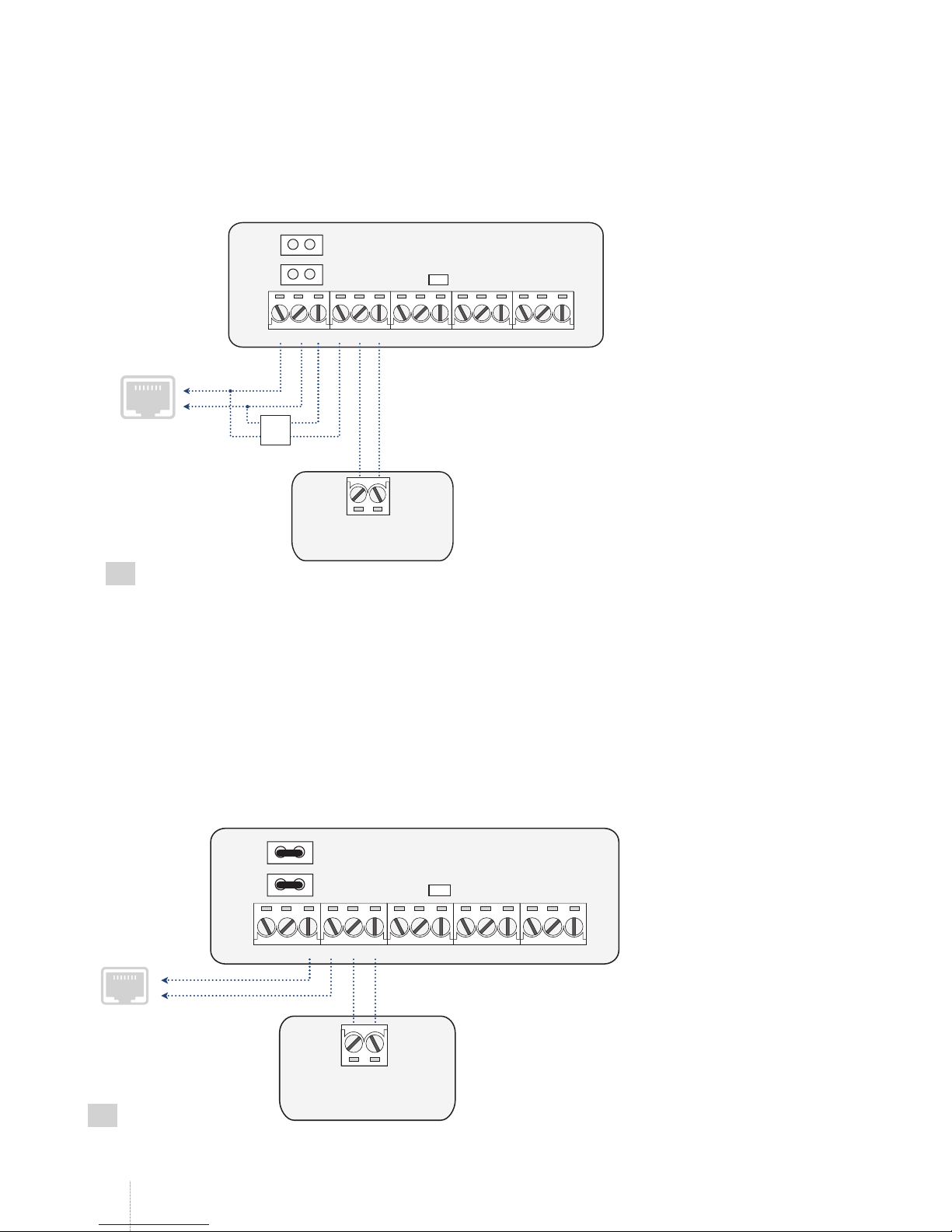
6.1. RING/TIP Interface
Using this communicaion wiring method, the communicator simulates the PSTN line presence for the alarm panel. Depending on the PSTN line
accessibility in the installaion area and user requirements, the communicator can be wired to the alarm panel using one of the following diagrams:
• No PSTN line – The communicaion link between the alarm panel and the monitoring staion is established using ET083 device in the middle.
The communicator retrieves data from the alarm panel and transmits it to the monitoring staion via the pre-conigured communicaion meth-
od. PSTN line is completely excluded from the communicaion process.
L1 L2 L3 L4 RING TIP
ALARM
PANEL
JP9
JP8
RING TIP
ET083
12
1. Connect the communicator’s RING and TIP terminals to the alarm panel’s RING and TIP terminals respecively.
2. DOT NOT set any jumpers on the communicator’s JP8 and JP9 pins.
• With PSTN Line Supervision – The communicaion link between the alarm panel and the monitoring staion is established directly via PSTN
line adding PSTN state (terminals L3 and L4) supervision provided by ET083 communicator. The communicator is not involved in the com-
municaion process while PSTN connecivity is available. In case of PSTN loss (terminals L3 and L4), the communicator will take over the
communicaion link and coninue data transmission via the pre-conigured communicaion method as described in No PSTN Line unil PSTN
connecivity is restored.
L1 L2 L3 L4 RING TIP
ALARM
PANEL
JP9
JP8
RING TIP
to PSTN line
PSTN
Socket
ET083
13
14
EN ET083 2G/3G COMMUNICATOR V1.0
1. Connect the communicator’s RING and TIP terminals to the alarm panel’s RING and TIP terminals respecively.
2. Connect L3 and L4 terminals to the PSTN socket.
3. Set the jumpers on the communicator’s JP8 and JP9 pins.
• With External PSTN Line Supervision – The communicaion link between the alarm panel and the monitoring staion is established directly
via PSTN line connected via PBX (private branch exchange) adding external PSTN state (terminals L1 and L2) supervision provided by ET083
communicator. The communicator is not involved in the communicaion process while PSTN connecivity is available. In case of external PSTN
loss (terminals L1 and L2), the communicator will take over the communicaion link and coninue data transmission via the pre-conigured
communicaion method as described in No PSTN Line unil PSTN connecivity is restored. In case of internal PSTN loss (terminals L3 and L4),
the PSTN connecivity would remain present.
L1 L2 L3 L4 RING TIP
ALARM
PANEL
JP9
JP8
RING TIP
PSTN Socket
to external
PSTN line
to internal
PSTN line
PBX
ET083
14
1. Connect the communicator’s RING and TIP terminals to the alarm panel’s RING and TIP terminals respecively.
2. Connect the communicator’s L1 and L2 terminals in parallel to the external PSTN line of the PBX connected to PSTN socket.
3. Connect L3 and L4 terminals to the internal PSTN line of the PBX.
4. DOT NOT set any jumpers on the communicator’s JP8 and JP9 pins.
For more details on how the PSTN loss is detected and managed by the communicator, please refer to 15. PSTN CONNECTION STATE SUPER-
VISION.
• With PSTN line supervision when Advanced KissOFF mode is enabled - The communicaion link between the alarm panel and the monitoring
staion could be established via all available communicaion channels. PSTN line could be conigured as Primary, Backup1 or Backup2 method. The com-
municator is involved in the communicaion process while PSTN connecivity is available. In case of PSTN loss (connect PSTN line to terminals L3 and L4,
and set the jumpers on the communicator’s JP8 and JP9 pins), the communicator will take over the communicaion link and coninue data transmission
via next pre-conigured communicaion method unil PSTN connecivity is restored. For more details on how the Advanced KissOf mode operates,
please refer to 19. ADVANCED KISSOFF MODE.
15
L1 L2 L3 L4 RING TIP
ALARM
PANEL
JP9
JP8
RING TIP
to PSTN line
PSTN
Socket
ET083

15
EN
ET083 2G/3G COMMUNICATOR V1.0
6.2. Keybus and Serial Interfaces
When using one of the following communicaion wiring methods, PSTN connecivity is supported only if Advanced communicaion
is enabled
Using Keybus communicaion wiring method Z1 and Z2 terminals convert into keybus interface for alarm panel connecion. In such case Z1 and Z2
terminals cannot be used as digital inputs.
In order to start using Serial communicaion wiring method, please obtain a cable adapter from your local supplier.
In both cases, the communicator retrieves serial data from the alarm panel and transmits it to the monitoring staion via the pre-conigured com-
municaion method.
ALARM
PANEL
JP9
JP8
BLK YEL GRN
Z2 Z1 COM
ET083
16
ALARM
PANEL
ET083
DEF TAMPER
SERIAL
SERIAL
17
1. a) Keybus interface connecion: Connect the communicator’s Z2 and Z1 terminals to the alarm panel’s GRN and YEL terminals respecively.
b) Serial interface connecion: Connect the communicator’s SERIAL interface to the alarm panel’s SERIAL interface using the cable.
2. Keybus interface connecion: If the communicator is powered from the external power supply unit, connect the communicator’s COM terminal
to alarm panel’s BLK (on some alarm panel models GND) terminal.
3. Select the alarm panel model from the list of the third-party alarm panels supported by the communicator:
• Paradox SP*
• Paradox EVO192*
• DSC 1616/1832/1864**
• DSC PC585**
4. Set up the Account number, which relects individual alarm panel’s pariion on the communicator.
To manage the aforemenioned parameters, please refer to the following coniguraion parameter.
Select third-party alarm
panel model
Conig
Tool This operaion may be carried out from the PC using the ELDES Coniguraion Tool sotware.
* Supported by Serial interface connecion.
** Supported by Keybus interface connecion.

16
EN ET083 2G/3G COMMUNICATOR V1.0
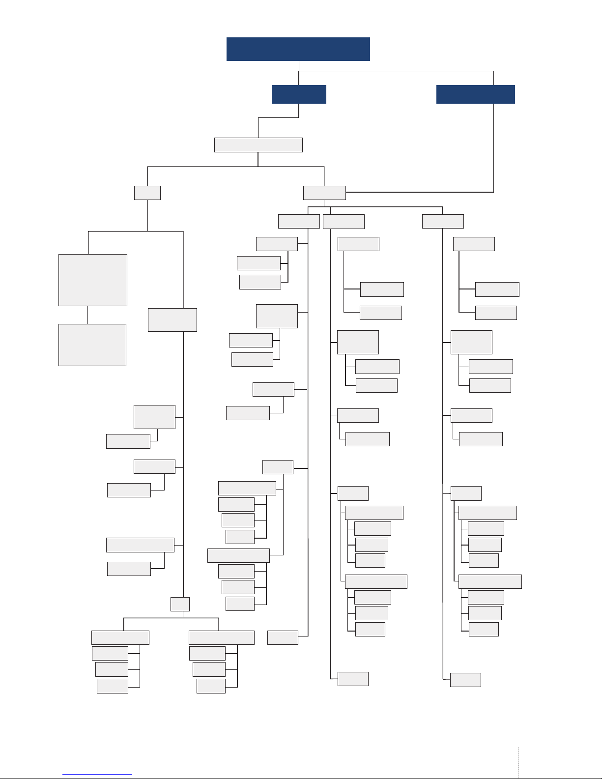
7. COMMUNICATION MODES AND METHODS
ET083 communicator supports Basic and Advanced modes and methods providing a variety of communicaion protocols. Please, note that some
protocols and communicaion methods are not supported in Basic mode and vice versa.
Basic mode –The communicaion methods supported by Basic Mode can be set as primary connecion only. Backup connecions are NOT available
in this mode.
Advanced mode – The communicaion methods supported by Advanced Mode can be set as primary or backup connecion. The user can set up to
2 backup connecions in any sequence order.
Basic mode* Advanced mode
Method Protocol Method Protocol
Voice Calls (direct channel
via 2G/3G audio)
Ademco Contact ID, 4+2 Voice Calls (2G/3G audio with data
bufering)
Ademco Contact ID, Scancom**
SMS – up to 5 user phone
numbers***
Ademco Contact ID
(converted into user-understand-
able text)
SMS – up to 5 user phone numbers*** Ademco Contact ID (converted
into user-understandable text)
IP (2G/3G/Ethernet via
ELAN3-ALARM) – 1 desina-
ion IP address
EGR100, Kronos, SIA IP IP (2G/3G/Ethernet via ELAN3-
ALARM) – up to 3 desinaion IP
addresses
EGR100, Kronos, SIA IP
Voice Calls (direct channel
via 2G/3G audio) + SMS –
up to 5 user phone number
Ademco Contact ID (by SMS:
converted into user-understandable
text)
PSTN**** Ademco Contact ID, Scancom**
CSD
* Supported only when ET083 is linked up with the alarm panel via RING/TIP interface (see 6.1. RING/TIP Interface). Does NOT support noii-
caions to the listed user by SMS text message and data report to the monitoring staion regarding PSTN line loss/restore events (see 15. PSTN
CONNECTION STATE SUPERVISION).
** Supported only when ET083 is linked up with the alarm panel via RING/TIP interface (see 6.1. RING/TIP Interface).
*** Can be used simultaneously with any communicaion method of Advanced mode (see 7.2.2. SMS).
**** By default, PSTN method is available for Primary communicaion ONLY. When Advanced KissOf mode is enabled, PSTN line is available as the
very last backup connecion in the enire communicaion sequence (see 19. ADVANCED KISSOFF MODE).
17
EN
ET083 2G/3G COMMUNICATOR V1.0
Voice
Calls
Voice
Calls
Voice
Calls
Voice
Calls
No PSTN
line
With PSTN line
supervision /
With external
PSTN line
supervision
Direct data
transmission to
the monitoring
staion
PSTN line is being
supervised by ET083
in case it is cut-of
Communicaion wiring method
RING/TIP
Set by PCB jumper
combinaion
Set by ELDES
Coniguraion Tool
Communicaion mode
Primary Backup 2
Basic Advanced
Data
bufering
Direct
channel
Data
bufering
Data
bufering
PSTNPSTNPSTN
ScancomScancom
Scancom
Scancom
Scancom Scancom
ELAN3-ALARM
ELAN3-ALARM
ELAN3-ALARM ELAN3-ALARM
EGR100
EGR100
EGR100 EGR100
EGR100 EGR100
EGR100 EGR100
Kronos
Kronos
Kronos Kronos
Kronos Kronos
Kronos Kronos
SIA IP
SIA IP
SIA IP SIA IP
SIA IP SIA IP
SIA IP SIA IP
Contact IDContact ID
Contact ID
Contact ID
Contact ID
Contact ID Contact ID
IP1... 3
IP1
IP1... 3 IP1... 3
2G/3G
2G/3G
2G/3G 2G/3G
Backup 1
Converted into
user-under-
standable text
Converted into
user-under-
standable text
By SMS: converted into
user-understandable text
Converted into
user-under-
standable text
When Advanced
Kissof mode
enabled
When Advanced
Kissof mode
enabled
Converted into
user-under-
standable text
Contact ID
Contact ID
Contact ID
Contact ID Contact ID
SMS
SMS
Voice Calls + SMS
SMS SMS
Keybus/Serial
CSD
CSD
CSD

18
EN ET083 2G/3G COMMUNICATOR V1.0
7.1. Basic Mode
The communicaion method of Basic mode is selected by jumper posiion on the SET/MODE pins on board. Basic mode features the following
communicaion methods:
• Voice Calls
• SMS
• Voice Calls + SMS
• IP
Basic mode is supported only when ET083 is linked up with the alarm panel via RING/TIP interface.
The jumper posiion on SET/MODE pins becomes inefecive as soon as Advanced mode is enabled.
7.1.1. Voice Calls Method
Using this method the communicator retrieves Ademco Contact ID or 4+2 data from the alarm panel and transmits it to the monitoring staion
via 2G/3G audio direct channel without inluencing the data itself. Before proceeding with any further coniguraion, please complete the steps
provided in 6.1. RING/TIP Interface.
To set the communicator to transmit data using this communicaion method, please proceed as follows:
1. On alarm panel: Enable Ademco Contact ID or Ademco 4+2 mode.
2. On alarm panel: Set valid Account number.
3. On alarm panel: Set the monitoring staion phone number (-s) in one of the following formats:
• Internaional (with 00) – The phone numbers must be entered staring with 00 and an internaional country code in the following format:
00[internaional code][area code][local number], example for UK: 0044170911XXXX1.
• Local – The phone numbers must be entered staring with an area code in the following format: [area code][local number], example for UK:
0170911XXXX1.
4. On ET083: Ensure that NO jumpers are set on SET/MODE pins on board.
18
SET
MODE
5. If required to override the Account number set on the alarm panel, please use Voice Calls communicaion method provided by Advanced mode
(see 7.2.1. Voice Calls Method). In addiion, please refer to 10. MONITORING STATION PHONE NUMBER AND ACCOUNT REPLACEMENT.
In the event of failure using this communicaion method, please refer to 8. 2G/3G MODEM SETTINGS or use Voice Calls communi-
caion method provided by Advanced mode (see 7.2.1. Voice Calls Method).
7.1.2.SMS Method
Using this method the communicator retrieves Ademco Contact ID data from the alarm panel, converts it into user-understandable text and delivers
to up to 5 listed users by SMS text message. Before proceeding with any further coniguraion, please complete the steps provided in 6.1. RING/
TIP Interface.
To set the communicator to transmit data using this communicaion method, please proceed as follows:
1. On alarm panel: Enable Ademco Contact ID mode.
2. On alarm panel: Set random Account number.
3. On alarm panel: Set random monitoring staion phone number; single digit is suicient.
4. On ET083: Set a jumper on MODE pins on board.

19
EN
ET083 2G/3G COMMUNICATOR V1.0
19
SET
MODE
5. On ET083: Connect the device to the computer via USB cable and run ELDES Coniguraion Tool sotware.
6. On ET083: Open Messaging Seings secion and proceed as follows:
a. Set up to 5 user phone numbers that will be permited to receive the data converted into user-understandable text by SMS text message. The
supported phone number formats are the following:
• Internaional (with plus) – The phone numbers must be entered staring with plus and an internaional country code in the following
format: +[internaional code][area code][local number], example for UK: +44170911XXXX1.
• Internaional (with 00) – The phone numbers must be entered staring with 00 and an internaional country code in the following for-
mat: 00[internaional code][area code][local number], example for UK: 0044170911XXXX1.
• Local – The phone numbers must be entered staring with an area code in the following format: [area code][local number], example for
UK: 0170911XXXX1.
b. Manage SMS text message content relecing the Ademco Contact ID data message structure.
c. Based on the alarm panel’s documentaion, ensure that all CID event codes supported by the alarm panel are added under the Messaging
Seings secion.
For more details on the parameters located under Messaging Seings secion, please refer to ELDES Coniguraion Tool sotware’s HELP ile.
7.1.3.Voice Calls+SMS Method
Using this method the communicator retrieves Ademco Contact ID data from the alarm panel, transmits to the monitoring staion via 2G/3G audio
direct channel without inluencing the data itself followed by data conversion into user-understandable text and delivery to up to 5 listed users by
SMS text message. Before proceeding with any further coniguraion, please complete the steps provided in 6.1. RING/TIP Interface.
To set the communicator to transmit data using this communicaion method, please proceed as follows:
1. On alarm panel: Enable Ademco Contact ID mode.
2. On alarm panel: Set valid Account number.
3. On alarm panel: Set the monitoring staion phone number (-s) in one of the following formats:
• Internaional (with 00) – The phone numbers must be entered staring with 00 and an internaional country code in the following format:
00[internaional code][area code][local number], example for UK: 0044170911XXXX1.
• Local – The phone numbers must be entered staring with an area code in the following format: [area code][local number], example for UK:
0170911XXXX1.
4. On ET083: Set a jumper on SET pins on board.
SET
MODE
20
5. On ET083: Connect the device to the computer via USB cable and run ELDES Coniguraion Tool sotware.
6. On ET083: Open Messaging Seings secion and proceed as follows:
a. Set up to 5 user phone numbers that will be permited to receive the data converted into user-understandable text by SMS text message. The
supported phone number formats are the following:
• Internaional (with plus) – The phone numbers must be entered staring with plus and an internaional country code in the following
format: +[internaional code][area code][local number], example for UK: +44170911XXXX1.
• Internaional (with 00) – The phone numbers must be entered staring with 00 and an internaional country code in the following for-
mat: 00[internaional code][area code][local number], example for UK: 0044170911XXXX1.
• Local – The phone numbers must be entered staring with an area code in the following format: [area code][local number], example for
UK: 0170911XXXX1.
b. Manage SMS text message content relecing the Ademco Contact ID data message structure.
c. Based on the alarm panel’s documentaion, ensure that all CID event codes supported by the alarm panel are added under the Messaging
20
EN ET083 2G/3G COMMUNICATOR V1.0
Seings secion, otherwise the communicator will be unable to deliver a certain event.
7. If required to override the Account number set on the alarm panel, please use Voice Calls communicaion method provided by Advanced mode
(see 7.2.1. Voice Calls Method). In addiion, please refer to 10. MONITORING STATION PHONE NUMBER AND ACCOUNT REPLACEMENT.
For more details on the parameters located under Messaging Seings secion, please refer to ELDES Coniguraion Tool sotware’s HELP ile.
In the event of failure using this communicaion method, please refer to 8. 2G/3G MODEM SETTINGS or use Voice Calls communi-
caion method provided by Advanced mode (see 7.2.1. Voice Calls Method).
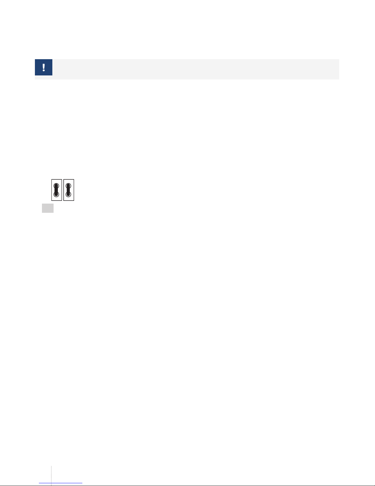
7.1.4.IP Method
Using this method the communicator retrieves Ademco Contact ID data from the alarm panel, converts it into EGR100, Kronos or SIA IP protocol and
transmits it to the monitoring staion via 2G/3G network or Ethernet connecion using ELAN3-ALARM device. Before proceeding with any further
coniguraion, please complete the steps provided in 6.1. RING/TIP Interface.
To set the communicator to transmit data using this communicaion method, please proceed as follows:
1. On alarm panel: Enable Ademco Contact ID mode.
2. On alarm panel: Set random Account number.
3. On alarm panel: Set random monitoring staion phone number; single digit is suicient.
4. On ET083: Set the jumpers on SET and MODE pins on board.
SET
MODE
21
5. On ET083: Connect the device to the computer via USB cable and run ELDES Coniguraion Tool sotware.
6. On ET083: Open IP / CSD Seings → IP Seings → IP 1 secion and set the following parameters:
• Server IP – Public IP address of the machine running EGR100/Kronos/SIA IP-based sotware.
• Port – Forwarded TCP/UDP port number of the machine running EGR100/Kronos/SIA IP-based sotware. Kronos and SIA IP-based sot-
ware require communicates via TCP port, while EGR100 supports both – TCP and UDP. UDP is highly recommended for EGR100 in order to
reduce the data traic consumpion.
• Protocol – Format of the data message transmited from ET083 to the monitoring staion’s IP address. Available protocols:
• EGR100 – ESR100 digital receiver and EGR100 middleware data format.
• Kronos – Kronos LT/Kronos NET monitoring staion sotware data format.
• SIA IP – SIA/IP data format complying with ANSI/SIA DC-09-2007 standard.
7. On ET083: If EGR100 is selected, it is MANDATORY to change the default Unit ID number, which is 0000, to any other 4-digit number.
8. On ET083: Select one of the following ways of data transmission:
• 2G/3G – 2G/3G connecion using the SIM card with acive mobile internet (data) service.
• ELAN3-ALARM – Ethernet (LAN) connecion using ELAN3-ALARM device.
9. On ET083: If 2G/3G is selected, please set the following parameters:
• APN – Access-point-name provided by 2G/3G operator.
• User Name – User name provided by 2G/3G operator.
• Password – Password provided by 2G/3G operator.
10. On ET083: If a ping signal is required in order to periodically verify the online status of the device, set the Test Period. For SIA IP protocol, please
enable Contact ID Ping parameter and change the CID event code (by default - 602) if required.
11. On ET083: Open Events Log secion to monitor the acivity.
12. On ET083: If required, the Account number set on the alarm panel can be overridden under System → Security Panel Seings secion. For
more details, please refer 10. MONITORING STATION PHONE NUMBER AND ACCOUNT REPLACEMENT.
For more details on the parameters located under IP / CSD Seings →IP Seings secion, please refer to ELDES Coniguraion Tool sotware’s
HELP ile.
For detailed step-by-step instrucions on how to establish the communicaion between ET083 communicator and EGR100 middleware, please refer
to the middleware’s HELP ile.
Table of contents
Other Eldes Cell Phone manuals


