elero 24 180.0101 User manual

DoorControl Nr. 24 180.0101 / 24 180.0301
Rolling door control for alternating current drives
GRUPPE
GÜN
T
HER
GB
It is important to observe these instructions in order to guarantee safety for persons!
Do not discard these instructions!
Incorrect assembly can cause serious injury.
• Connections to the mains must be carried out by specialised personnel.
• The control must be disconnected from the mains during connestion work.
• The mains disconnection mechanism must be secured against unintentional and unauthorised
restarting and shoule always be accessible.
• Powered doors with pulsed or automatic operation must fulfil EN 12453.
• With external evaluation devices connect the 8.2 kOhm resistor in series with the switch contact.
• Caution: A moving door panel must not pose a risk of injury or damage.
• An 8.2 kOhm resistor can be connected in the CLOSED direction in the case of roller shutter drives.
• Caution: The roller shutters must not pose a risk of injury or damage.
180
130
60
230 V Mains terminals Fuse
6,3 A tr.
Selector
switch
S 1
LED
S 2
Hold-open time
Proigramming
button
S 3
Integrated radio
receiver or slot for
radio receiver 24 V terminals
Operating appliances
Warning!
Advice: Only tubular drives with mechanical limit switches can be connected.

DoorControl
2
Summarised description of DoorControl
•
Programmable motor run time monitoring (to be pro-
grammed with a self-retention operating mode [DIPI]
)
•
Diagnosis display using LED
•
Connection of a locking mechanism for the door edges
Opto-electronic switch actuator (OSE) by Fraba or an
8.2 kOhm resistance actuator
.
•
Testing of the signal path (in the event of a faulty locking
mechanism for the door edges in CLOSE dead man operation)
•
Possible connection for the CLOSE pre-limit switch
•
Possible connection for the CLOSE light barrier
•
Possible coding for dead man operation / self-retention (DIP1)
•
Possible coding for free movement / reversing up to the
open end position when the locking mechanism for the
door edges responds (DIP2)
•
Possible coding for lighting controller impulse /
120 seconds, failure notification or green traffic light
•
Radio receiver integrated or pluggable via the connector
•
Connectable external radio receiver
•
Possible connection for garage lighting / failure
notification or green traffic light
•
Possible connection for red traffic light, illuminates when
the door moves, flashes in the intermediate positions and
flashes with increased frequency during failure (run time,
locking mechanism for the door edges etc.)
Important assembly advice
1.
Assemble the control boxes near the door
(minimum height 1.5m)
2.
Assemble the activation buttons and / or key-operated
push buttons near the door with a complete overview of
the door movement area
.
3.
Open the control box and connect the motor cable to the
control.
4.
Motor feed cable: max. 15m long, min. 0.75mm
2
5.
Connect the touch keyboard in the correct position
(observe the coding)
6.
Connect the earthing contact connector, the green LED1
illuminates on the control board
.
7.
Direction of rotation control: press the OPEN key, the drive
rotates in the opening direction
.
Should this not be the case, disconnect the Schuko connector
from the mains and change the motor cables U + V.
8.
Reconnect the Schuko connector and check the direction
of rotation once again
.
9.
The limit switch position is stipulated in the drive instruc-
tion manual
.
10.
Only connect the operation devices when disconnected
from the mains
.
General information
DoorControl is designed for use with automatically operated
door installations with 230 V alternating current drives
.
The control is delivered with a 1.5m long connecting cable
with an earthing contact connector and a touch keyboard
(Open-Stop-Close) built into the casing cover
.
The automatic
closing mechanism, with or without radio receiver, is built
into the control
.
All signal inputs operate with 24 V voltage and are galvani-
cally separated by optocouplers
.
A 24 V DC, maximum 150 mA,
mains unit is integrated for supplying power to the light
barriers andcommands.
.
Tecnical features:
Power supply 230 V/AC 50/60 Hz
On site fuse max. 10 A
Power consumption max. 6 Watt
Switching power max. 6 A
Breaking capacity max. 1300 VA
Protection class IP 54
Internal fuse 6,3 A tr.
Dimensions 180 x 130 x 60 mm
Operating temperature – 10 to +50 °C
TÜ certified EN 12453
Modes of operation
Setting in the switching block
S 1 DIP switch position
Dead man Dead man in OPEN and CLOSE
Self-retention without programmed motor run time only in OPEN
Reversing up to the limit switch When the locking mechanism for the door edges
Free movement responds the opening direction switches on.
Relay K3 switches Lighting control via the stair light timer etc. with each
an impulse (approx. 1 sec.) opening command
Relay K3 switches Direct lighting control (light bulbs etc.)
approx. 120 secs. with each opening command
Relay K3 switches a persistant e. g. running time exceeded
command during failure
Relay K3 switches on when the For controlling the red-green-traffic light
end position is upward (green traffic light)
ON
1
ON
1
ON
1
ON
1
ON
1
ON
1
ON
1
ON
1
ON
1
ON
1
ON
1
ON
1
DIP 1
DIP 1
DIP 2
DIP 2
DIP 3
DIP 4
DIP 3
DIP 4
DIP 3
DIP 4
DIP 3
DIP 4
DoorControl
3
Functions
➱
Motor run time monitoring
DoorControl includes programmable motor run time moni-
toring which automatically switches the drive off in the
event of excessive motor run time
.
In order to programme
the motor running time the drive should be taken to the
CLOSE door position
.
Set
DIPI
to the ON position
.
Briefly press programming
button S3, LED 2 illuminates, now move the drive in self-
retention until reaching the limit switch door OPEN
.
LED2
goes out, the motor run time is now programmed
..
If the programming button S3 is pressed for more than
5 secs. (LED2 goes out) the run time monitoring is reset
to the maximum value (0 secs.).
➱
Locking mechanism for the door edges (OSE or 8,2 kOhm)
Should the locking mechanism for the door edges be activa-
ted during a CLOSING movement, the control switches over
to the opening direction (reversing or free movement). If the
CLOSE pre-limit switch is pressed, the drive is stopped. If the
locking mechanism for the door edges is faulty, the drive can
be operated with the built-in touch keyboard and the exter-
nal triple switch in dead man operation.
➱
Light barrier
If the light barrier is activated during a CLOSING move-
ment, the control switches over to the opening direction
and the drive moves up to the OPEN end position
.
When
the automatic closing mechanism is switched on, the hold-
open time is reinitiated
.
Should the installation be in an
intermediate position and the light barrier is activated, the
opening direction is started
.
➱
Radio remote control Channel 1
The integrated or the internally pluggable radio receiver, as
well as the external input FS (terminal 13+14) change
function with each activation
.
(
Switching sequence UP-STOP-DOWN-UP
. . .)
When the automatic closing mechanism is switched on the
radio remote control always switches on the opening
direction
.
With each subsequent command, the hold-open
time is reinitiated
.
The programming must be based on the radio remote
control in use
.
➱
Radio remote control Channel 2
Relay K3 can be additionally controlled with the second
channel
.
➱
Automatic closing mechanism
The automatic closing mechanism can be swit-
ched on and off with the rotary switch S2.
When the automatic closing mechanism is
switched on, the preliminary warning time swit-
ches on for approximately 5 secs. at the end of
the hold-open time. The closing procedure is then started.
The door can be opened with the “On” timer contact (terminal 10
a
and closed again with “Off” by the adjusted automatic door-edge
security system.
If the locking mechanism for the door edges has been
activated 3 times before reaching the CLOSE limit switch
the automatic closing mechanism becomes inactive
.
Level 0
Active red traffic light and error message
Level 1
Active red traffic light, error message flashing
Level 2
Automatic closing function on, “hold open” time 10 se
Level 3
as above 20 seconds
Level 4
as above 30 seconds
Level 5 as above 40 seconds
Level 6 as above 50 seconds
Level 7 as above 60 seconds
Level 8 as above 60 seconds (after the light barrier
is CLOSED, the “hold open” time reduced
by approx. 4 secs)
Level 9 Automatic closing function on, “hold open” time 10 sec
LED diagnosis
LED 5 (red)
Stop button activated (terminals 9+10)
LED 4 (red)
Light barrier activated
LED 3 (red)
Illuminates when the locking
mechanism for the door edges is
faulty or activated
LED 2 (yellow)
Programme motor run time
/
radio reception
LED 1 (green) Power
(operating voltage)
Flashes during OPEN and CLOSE
movement
Flashes when the hold-open time runs out
LED 1 (green)
+ LED 3 (red) Flashes when the running time is exceeded
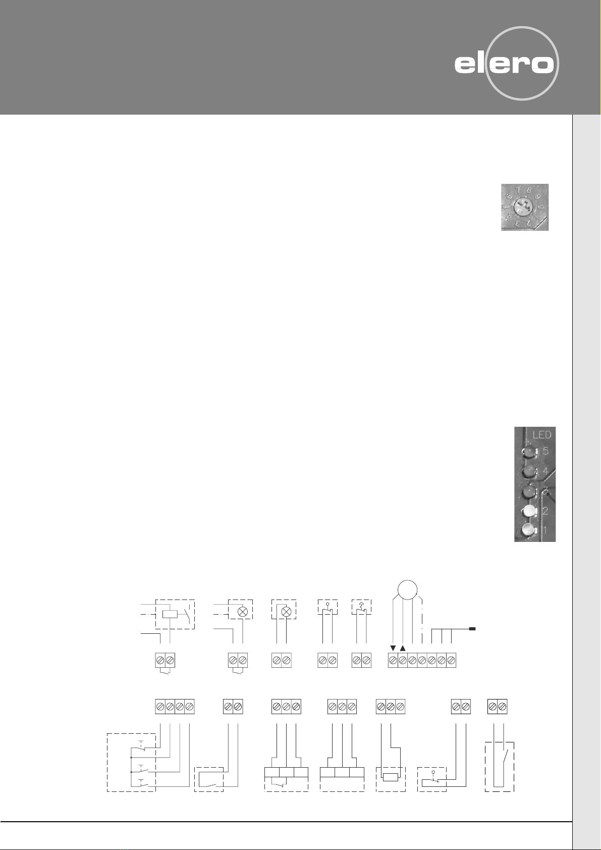
mains 230V/AC
M
1~
-+ OUT
Safety
switch
error message
Red traffic light or
Light or
green traffic light
Light or failure notification
with latching relay
Emergency
stop
Triple switch
Stop
Up
Down
pull switch
Radio remote
control,
Light barrier
closing direction
Terminals 15/17
max. 150 mA
Fraba OSE
GN BN WS
R 8,2 kOhm
Pre-limit switch CLOSE
or
locking mechanism for the door edges
max. 10A
Fuse on site
21 22
NPEPE N L12345678
1091211 1715 16
K3
L
N
PE
L
PE
N
87
K3
13 14 1918 20 2018 19
inputs/outputs
operating elements
Safety devices Neutralization
24V DC inputs/outputs
230V AC
Terminal diagram DoorControl
230 V/max. 60 W
10 11
Timer
max. 230 V/60 W

MANUFACTURERE'S DECLARATION
in compliance with the machinery directive 98/37/EU,
EMC directive 89/336/EEC;
low voltage directive 73/23/EEC
We hereby declare that the following product (s) is (are) in compliance
with the directives of the European Community.
Product designation:
DoorControl
The compliance of the described product (s) with the relevant
safety regulations as according to the directives is demonstrated by compliance
with the following standards:
xEN 12453 Safety of use of power-operated doors
xEN 50178
xEN 60204-1
xEN 50082-1+2
xEN 55014-1+2
xEN 60555 parts 1-3
The commissioning of this (these) product (s) is not permitted until ascertained that the
machine in which the abovementioned product (s) is (are) installed is in compliance with the
directives or the relevant national standards.
Beuren, 25. 06. 2002
elero GmbH
Antriebstechnik
Ulrich Seeker Linsenhofer Str. 59-63
EC Representative D-72660 Beuren
2020
13 305.6101
Technical parameters subject to change
04/07
elero UK Ltd.
Foundry Lane – Halebank
Widnes, Cheshire WA8 8TZ
Tel. (44) 870/24042 19
Fax (44) 870/240 4086
www.elero.com
elero GmbH
Antriebstechnik Linsenhofer Straße 59–63
D-72660 Beuren
Telefon (070 25) 13-01
Telefax (070 25) 13-212
Telefon (070 25) 13-01
Telefax (070 25) 13-212
www.elero.com
This manual suits for next models
1
Other elero Control Unit manuals


