Elite Fitness Phantom User manual

2
CONTENTS
Important Safety Instrucons 3
Product Specicaons 4
Assembly Instrucons 5
Seng your Spin Bike Up 13
Care and Maintenance 15
Maintenance Log 16
Limited Warranty 17
Warm-Up Exercise 18
Training Stages 19
Parts List 20
Thank you for purchasing the Elite Phantom Spin Bike.
For over 20 years, Elite Fitness™ has been New Zealand’s largest supplier of tness equipment. Our
aim and vision is to provide you Elite™ branded products, tested to the highest standard for quality
and biomechanics at the best possible price.
Please read through this manual to familiarise yourself with the operaon of your new Elite
Phantom Spin Bike. Doing so will help to insure that you get the most out of your machine,
enjoying safe and eecve workouts ahead.
Even though we go to great eorts to ensure the quality of each product we produce, occasional
errors and or omissions do occur. In any event should you nd this product to have either a
defecve or a missing part, please contact us for a replacement.
SERVICE & WARRANTY
For service and warranty assistance please visit:
www.elitetness.co.nz/service
Online forms are available for Service, Warranty and Parts requests.
(09) 258 9067
Elite Fitness HQ
11 George Bourke Drive
Mt Wellington
Auckland, New Zealand
info@elitetness.co.nz
0800 2 438 348
www.elitetness.co.nz


4
— Only carry out training work on the equipment when it is in perfect working order. Only use
original spare parts in the event of a repair.
— Do not use strong solvents for cleaning, and only use the tools supplied, or suitable ones of
your own, for any repairs that may be required. Please dispose of the packaging and any parts
that have to be replaced subsequently (all parts for the unit) at suitable collecng points or
containers with a view to saving the environment.
— DO NOT extend the seat stem past the warning line “Max” when adjusng the seat height.
— Not for therapeuc use.
WARNING: Before beginning any exercise program, consult your physician. This is especially
important for persons with pre-exisng health problems. The seller assumes no responsibility for
personal injury or property damage sustained by or through the use of this product.
SERVICE HINTS: The high quality standard of this product only will be kept if you on a regular
basis check all screw-connecons and moving parts on proper ng. Damaged parts have to be
changed immediately. During the me of repair the product must not be used by anybody.
IMPORTANT HINTS:
A) This product has been tested in accordance with the requirements of EN 957-1/A1, EN 957-5,
standard, Class HA (HOME USE). The maximum load is limited to 150KGS.
B) Parents should be aware of the risk factor of young children playing on tness equipment
unaended. Make sure that the children are instructed properly in the use of the product
and in the controlled execuon of the dierent exercise. Misuse of the product could result in
serious injury
PRODUCT SPECIFICATIONS
User Weight Capacity: 150kg
Dimensions: W11” x L45”x H37“
Shipping Weight: 62.9kg
Net Weight: 57.5kg
SKU#: 96M-1
5ELITE phanTom SpIn BIkE aSSEmBLy manuaL
ASSEMBLY INSTRUCTIONS
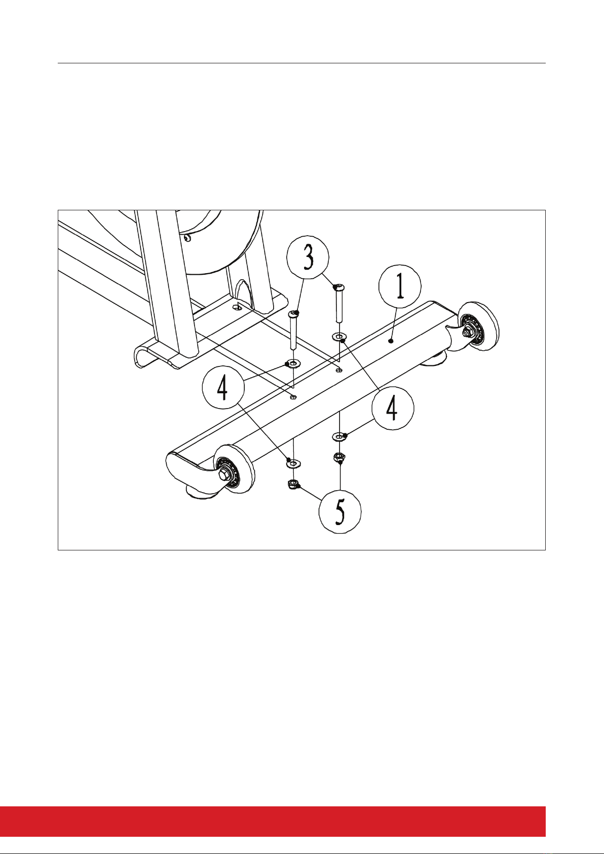
STEP 1
— Posion the Front Stabilizer (1) on the Frame Bracket making sure the transport wheels are
facing up and toward the front of the bike (as shown).
— Aach the Stabilizer with two Hex Screws (3), four Flat Washers (4) and two Nylon Nuts (5).
Do not over ghten as the Stabilizer may buckle.

6
STEP 2
— Posion the Rear Stabilizer (2) on the Frame Bracket and x using two Hex Screws (3), four Flat
Washers (4) and two Nylon Nuts (5). Do not over ghten as the Stabilizer may buckle.
NOTE: Ensure the Levelling Feet on both the Front and Rear Stabilizers are aached securely.
7ELITE phanTom SpIn BIkE aSSEmBLy manuaL
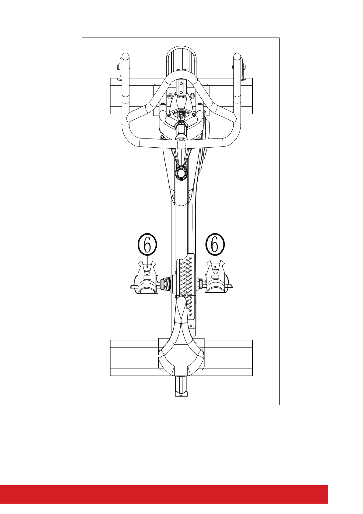
STEP 3
— The Pedals (6) are marked “L” and “R” for Le and Right. Connect them to their corresponding
crank arms. The right crank arm is on the right-hand side of the cycle as you sit on it.
NOTE: The Right Pedal should be twisted on clockwise and the Le Pedal anclockwise. If
possible, apply some grease to the crank prior to aaching.
8
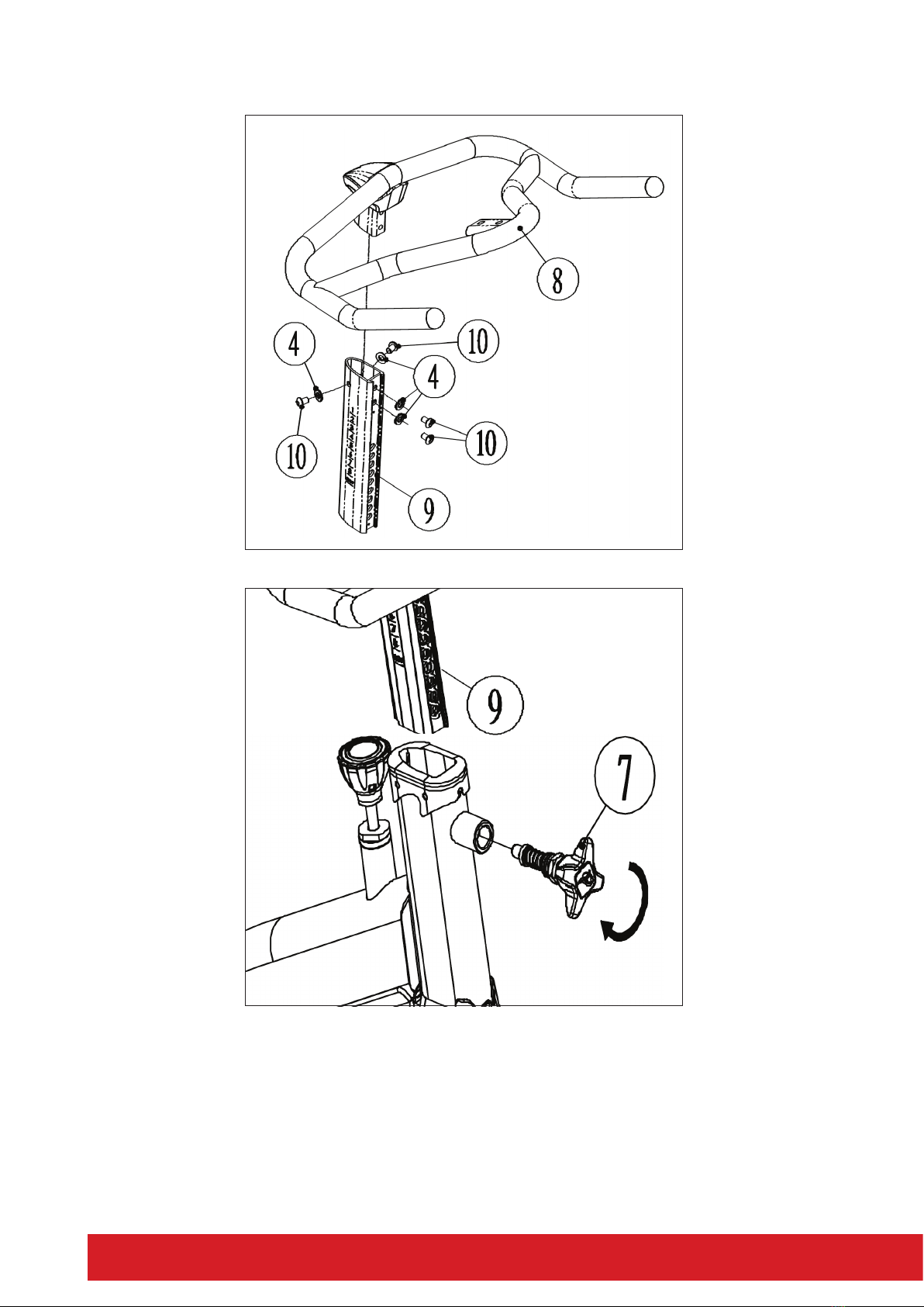
STEP 4
— Slide the Handlebar (8) into the Handlebar Post (9) and aach using four Socket Hex Screws (10)
and four Flat Washers (4).
— Insert the Handlebar Post (9) into the Main Frame Tube and use the Adjustment Handle (7) to
hold in place by turning clockwise using the Wrench (A). Ensure the Adjustment Handle (7) is
ghtened rmly.
9ELITE phanTom SpIn BIkE aSSEmBLy manuaL
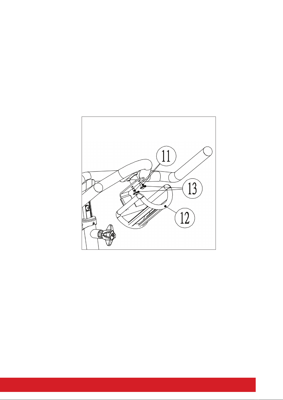
STEP 5
— Aach the Bole Holder (12) to the Handlebar (8) using two Socket Hex Screws (11) and two
Flat Washers (13).

10
ADJUSTING THE TENSION
Increasing or decreasing the tension allows you to add variety to your workout sessions by
adjusng the resistance level of the bike.
— To increase tension and increase resistance (requiring more strength to pedal), turn the
Emergency Brake & Tension Control Knob (37) clockwise.
— To decrease tension and increase resistance (requiring less strength to pedal), turn the
Emergency Brake & Tension Control Knob (30) counter clockwise.

11ELITE phanTom SpIn BIkE aSSEmBLy manuaL
EMERGENCY BRAKE FUNCTION
The same knob that allows you to adjust the tension of the bike also doubles as the Emergency
Brake. Use this safety feature in any situaon where you would need to get o the bike and/or stop
the bike’s ywheel.
— Press down the Emergency Brake & Tension Control Knob (37) on the Main Frame to stop the y
wheel. ONLY when the ywheel has stopped, will it be safe to remove feet from pedals.
— Do not stop pedalling: doing so could result in serious injury.
— Do not aempt to stop the Fly Wheel by hands, feet or any other device not indicated in this
instrucon.

13ELITE phanTom SpIn BIkE aSSEmBLy manuaL
Having your bike seat adjusted to the right
height is essenal for a comfortable ride,
ecient pedalling and avoiding injury. There
are 2 adjustments located on the seat post. The
rst is a vercal height adjustment, the second
is for horizontal seat posion. Although there
are many methods and opinions on the opmal
saddle seng, the following is a quick an easy
method to get started. Further adjustments can
be made aerwards to opmise your posion
and comfort.
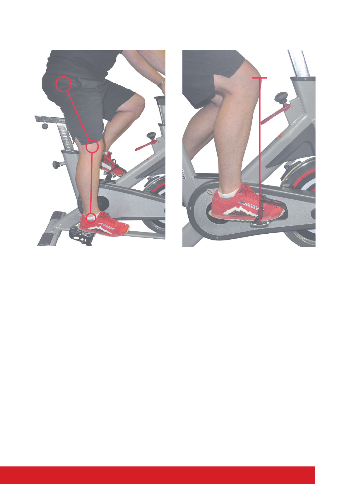
Saddle Height Adjustment
— Place your heels on the bike pedals and
pedal backward. Your legs should be fully
extended with your knees straight. If your
hips rock from side to side while pedalling
backward, the seat is too high.
— Place the ball of your foot on the pedal.
There should now be a slight bend in your
knee when the pedal is at its lowest point.
This is a good starng point.
Adjusting the Seat Fore-and-Aft Position
Once you’ve adjusted seat height, it’s me
to nd the correct fore-and-a posion of
the saddle. This determines where you sit
in relaonship to the crank set (where the
pedals are aached), which helps decide how
comfortable and ecient you’ll be when riding.
This also minimises stress to the knee by being
in a more neutral posion.
If you want to try to check the fore-and-a
seng at home, you will need a second person
and a plumb line (a length of string with a nut
or washer ed on the end will work ne).
Whilst sing on the seat saddle bring your right
crank arm around and have your helper stop
the crank when the pedal is at three o’clock
or parallel with the oor. Note that for this
measurement to be accurate, your shoes must
be correctly posioned on the pedals (the balls
of your feet should be over the pedal axles).
Saddle Height Adjustment Adjusting the Seat Fore-and-Aft Position
SETTING YOUR SPIN BIKE UP
14
Please note: The spin bikes shown in the ‘setting up your spin bike’ section are for demonstration purposes only and your
spin bike my vary in aesthetics and features.
Holding this posion, have your helper place
the end of the plumb line (line of string with
nut/washer) on the front of your leg, at a point
just below the bony protrusion that’s beneath
the kneecap.
The plumb line’s weight should hang over your
shoe. Check again to ensure that the crank-arm
and pedal are level. By looking at the plumb
line the knee should be in alignment with the
centre spindle or axle of the pedal. Adjust the
saddle to the correct posion then ghten the
locking pin.
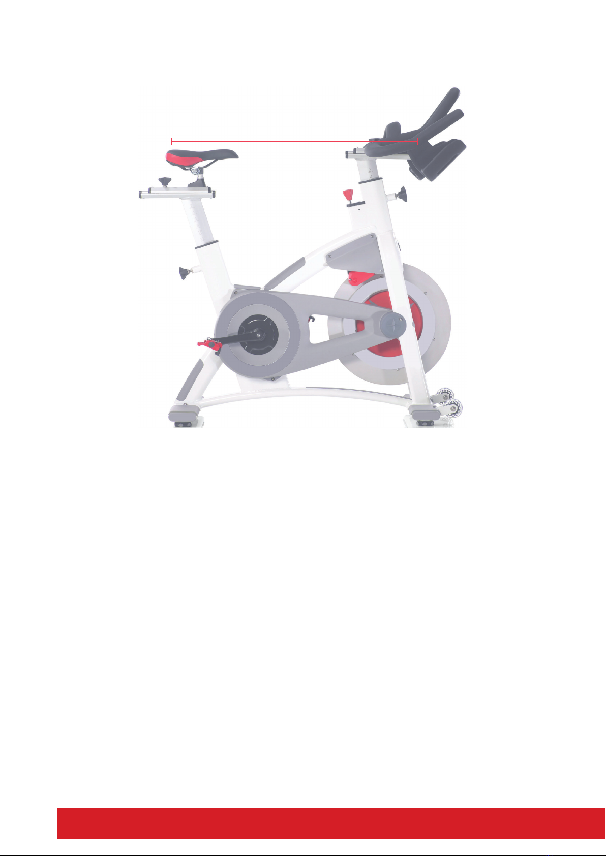
Handle Bar Adjustment
The posioning of the handlebars can be
dependent on the bike design and adjustability
available.
To minimise back strain, adjust the height
to a level that is comfortable for you. We
recommend the handlebars be posioned at
the same height level as the bike seat as a good
starng point.

16
eg:
MAINTENANCE LOG
Prolong the life of your spin bike by performing periodic maintenance checks. Not only does this
ensure your machine is in full working order, but it will save you service costs in the long run.
Every me you perform maintenance, record the date and if you can, the distance and hours
operated.
DATE HOURS DISTANCE
MECHANICAL
MAINTENANCE FRAME SERVICE
COMMENTS
Brake Chain /
Belt Cleaned Seat /
Pedals
01/06 15 16.5km √√√√ none

17ELITE phanTom SpIn BIkE aSSEmBLy manuaL
Warranty Range
Damage in correct maintenance and normal operaons (not facous factors). Warranty card to
the original purchaser, shall not be transferred.
Warranty Time
HOME USE
— 10 Years Frame
— 1 Year Parts and Labour
The following conditions are not under warranty range:
A) As a result of abuse, neglect, accident, or unauthorized modicaon;
B) The damage due to incorrect assembly or adjustment of the machine;
Repair and Maintenance Service
Please contact our Elite Fitness Service Department at eliteservice@elitetness.co.nz or visit
www.elitetness.co.nz for any service related issues or advice on preventave maintenance
servicing procedures.
LIMITED WARRANTY

18
Warm up exercise is important in preparing the muscles for acvity whilst minimising the risk
of injury. You may choose to warm up with a light/brisk walking pace for 5-10 minutes before
stopping and performing some simple stretches. (As shown in the pictures below)
— Hamstring Stretch (Standing) Keep your knees slightly bent and slowly lean forward, back
and shoulders relaxed, reaching towards your toes. You should feel the tension and slight
discomfort in your hamstring muscles. Hold for 15-20 seconds.
Repeat 2-3 mes.
— Hamstrings Stretches (Seated) Sing on the oor preferably on
a mat, put one leg straight, the other inward and close to the
inside of the straight leg. Lean forward from the hips, reaching
towards your toes. Hold for 10-15 seconds, and relax. Repeat 3
mes for each leg (See picture 2).
— Crus and Feet Tendon Stretches Standing with two hands on
the wall or tree, one leg behind. Keeping your legs straight and
the heel on the ground, lean forward towards the wall or tree.
Hold for 10-15 seconds, and relax. Repeat 3 mes for each leg
(See picture 3).
— Quadriceps Stretches Keeping your balance with your le hand
holding onto a wall or staonery xture, grasp your right foot
with your right hand and stretch your right heel toward your
buocks slowly, unl you feel the stretch in the front of your
thigh. Hold for 10-15 seconds, and relax. Repeat 3 mes for
each leg (See picture 4).
— Sartorius (Inner Muscles of the Thigh) Muscle
— Stretches Sing down with the soles of your feet or shoes
together and your knees posioned outward. Pull your feet
towards your groin unl you can feel the stretch. Hold for 10-15
seconds, and relax. Repeat 3 mes (See picture 5).
WARM-UP EXERCISE
19ELITE phanTom SpIn BIkE aSSEmBLy manuaL
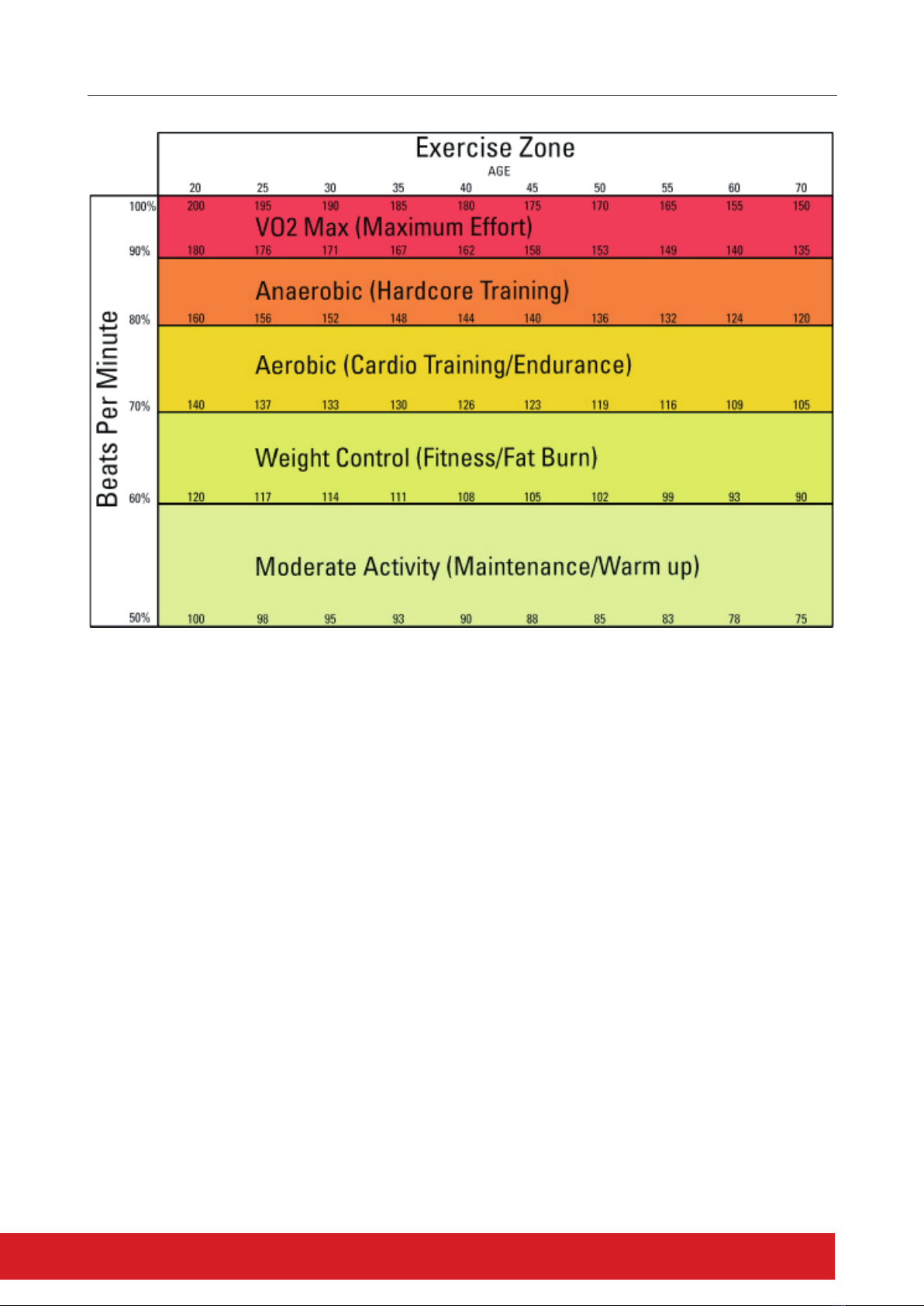
Cardiovascular training plays an important part in maintaining a healthy heart and lung funcon, so
it’s no surprise we should be paying aenon to how quickly our heart beats during exercise. The
chart above outlines a range of heart rate training zones determined by the individual’s age and
workout goals to ensure you train safely and eecvely.
Heart Rate can be measured by using the radial (wrist) or carod (neck) pulse using your index and
middle ngers, counng the beats for 10 seconds and mulplying by 6. Alternavely, the use of a
Wireless Telemetry Heart Rate strap and watch will give you an accurate Beats Per Minute (BPM)
reading.
220 – AGE = TMHR (Theorecal Maximum Heart Rate)
TMHR x 85% = (Upper Training Limit) bpm (Beats per Minute)
TMHR x 65% = (Lower Training Limit) bpm
Note: Contact heart rate may provide inaccurate readings and is designed only as a guide
Example: 220 – 39 = 181 bpm
181 x 85% (0.85) = 154 bpm (Upper Training Limit)
181 x 65% (0.65) = 118 bpm (Lower Training Limit)
TRAINING STAGES

20
PARTS LIST
We recommend 2 people assist in assembling this unit. Place all parts of the spin bike in a cleared
area and remove the packing materials. Do not dispose of the packing materials unl assembly is
completed. Before you start installaon, inspect and prepare all parts and screws featured in this
manual. When you open the carton, you will nd the following parts:
1Front Stabilizer 1
2Rear Stabilizer 1
3Socket Hex Screw (M8x1.25x55L)
(SUS304) 4
4Flat Washer (M8 φ19xφ8.5x1t) 12
5Nylon Nut M8x1.25 (SUS304) 4
6Pedal (Le/Right) 2
7Adjustment Handle 1
8Handlebar 1
9Handlebar Post 1
10 Socket Hex Screw (M8x1.25x12L) 4
11 Socket Hex Screw (M6x1.0x15L) 2
12 Water Bole Holder 1
13 Flat Washer (M6 φ16xφ6.5x1t) 2
PART
NO. DESCRIPTION Q’TY
1 2
3 4
7 8
9 10
5 6
11 12
13
This manual suits for next models
1
Table of contents
Other Elite Fitness Exercise Bike manuals

Elite Fitness
Elite Fitness FALCON User manual

Elite Fitness
Elite Fitness NERO User manual

Elite Fitness
Elite Fitness DEFENDR User manual

Elite Fitness
Elite Fitness WAVE ROWER User manual

Elite Fitness
Elite Fitness VO2 User manual

Elite Fitness
Elite Fitness RAZOR R9+ User manual

Elite Fitness
Elite Fitness COLT User manual

Elite Fitness
Elite Fitness VO5 User manual

Elite Fitness
Elite Fitness Pursuit Air User manual

Elite Fitness
Elite Fitness Destroyer User manual


