Elite Fitness LYNX User manual

ASSEMBLY MANUAL
Record serial number
Elite Lynx Recumbent Bike

2
CONTENTS
Important Safety Instrucons 3
Product Specicaons 4
Check List 5
Assembly Instrucons 6
Seat adjustment 16
Display Console 17
Care and Maintenance 20
Maintenance Log 21
Limited Warranty 22
Warm up Exercises 23
Training Stages 24
Parts 26
Exploded Drawing 28
Notes 29
Thank you for purchasing the Elite Lynx Recumbent Bike.
For over 20 years, Elite Fitness™ has been New Zealand’s largest supplier of tness equipment. Our
aim and vision is to provide you Elite™ branded products, tested to the highest standard for quality
and biomechanics at the best possible price.
Please read through this manual to familiarise yourself with the operaon of your new Elite Lynx
Recumbent Bike. Doing so will help to ensure that you get the most out of your machine, enjoying
safe and eecve workouts ahead.
Even though we go to great eorts to ensure the quality of each product we produce, occasional
errors and or omissions do occur. In any event should you nd this product to have either a
defecve or a missing part, please contact us for a replacement.
SERVICE & WARRANTY
For service and warranty assistance please visit:
www.elitetness.co.nz/service
Online forms are available for Service, Warranty and Parts requests.
(09) 258 9067
Elite Fitness HQ
28 Morrin Road, Saint Johns
Auckland, New Zealand
info@elitetness.co.nz
0800 2 438 348
www.elitetness.co.nz

3ELITE VO2 EXERCYCLE ASSEMBLY MANUAL
IMPORTANT SAFETY INSTRUCTIONS
The following denion applied to the word “WARNING” when used in this manual:
Used to call aenon to POTENTIAL hazards that could result in
personal injury.
READ ALL INSTRUCTIONS BEFORE USING THE MACHINE
This product has been designed for home use only. Product liability and warranty condions will
not be applicable to products being subjected to professional use or products being used in a
commercial environment. e.g Gym Centre, Rerement Centre, Home Based PT Studio and Physio.
This exercise machine is built for opmum safety. However, certain precauons apply whenever
you operate a piece of exercise equipment. Be sure to read the enre manual before you assemble
or operate your machine. In parcular, note the following safety precauons.
— Read all instrucons in this manual before using this equipment.
— Use the machine only for its intended use as described in this Manual.
— Inspect and ghten all the loose parts before this equipment is used.
— Keep hands away from moving parts.
— Keep children and pets away from the machine at all mes. DO NOT leave children unaended
in the same room with the machine.
— Before using the machine to exercise, always do stretching exercises to properly warm up.
— Inspect the machine before each use; make sure all of the connecons are ghtly secured.
— Only one person at a me should use the machine.
— If the user experiences dizziness, nausea, chest pain, or any other abnormal symptoms, STOP
the workout at once. CONSULT A PHYSICIAN IMMEDIATELY.
— Posion the machine on a clear, levelled surface. DO NOT use the machine near water
or outdoors.
— Always wear appropriate workout clothing when exercising. DO NOT wear robes or other
clothing that could become caught in the machine. Sporng shoes are recommended when
using the machine.
— Do not place any sharp object around the machine.
— Disabled persons should not use the machine without a qualied person or physician
in aendance.
— Never operate the machine if the machine is not funconing properly.
— Only carry out training work on the equipment when it is in perfect working order. Only use
original spare parts in the event of a repair.
— Do not use strong solvents for cleaning, and only use the tools supplied, or suitable ones of
your own, for any repairs that may be required. Please dispose of the packaging and any parts
that have to be replaced subsequently (all parts for the unit) at suitable collecng points or
containers with a view to saving the environment.
— DO NOT extend the seat stem past the warning line “Max” when adjusng the seat height.
— For therapeuc use.

4
WARNING: Before beginning any exercise programme, consult your physician. This is especially
important for persons with pre-exisng health problems. The seller assumes no responsibility for
personal injury or property damage sustained by or through the use of this product.
SERVICE HINTS: The high quality standard of this product only will be kept if you, on a regular
basis, check all screw connecons and moving parts on proper ng. Damaged parts need to be
changed immediately. During the me of repair the product must not be used by anybody.
IMPORTANT HINTS:
A) This product has been tested in accordance with the requirements of EN 957-1/A1, EN 957-5,
standard, Class HA (HOME USE). The maximum load is limited to 100KG.
B) Parents should be aware of the risk factor of young children playing on fitness equipment
unattended. Make sure that children are instructed properly in the use of the product and in
the controlled execution of the different exercises. Misuse of the product could result in
serious injury.
PRODUCT SPECIFICATIONS
User Weight Capacity:
Dimensions: 1190x245x575mm
Shipping Weight:
Net Weight: 26kgs
Power Requirements
100Kgs
29Kgs

5ELITE VO2 EXERCYCLE ASSEMBLY MANUAL
CHECK LIST
6
ASSEMBLY INSTRUCTIONS
Make sure there is enough space before installing your recumbent bike. Before you install
your recumbent bike, make sure you have all parts all ready before assembling. (Refer to
exploded drawing of all the key parts/ components to install).
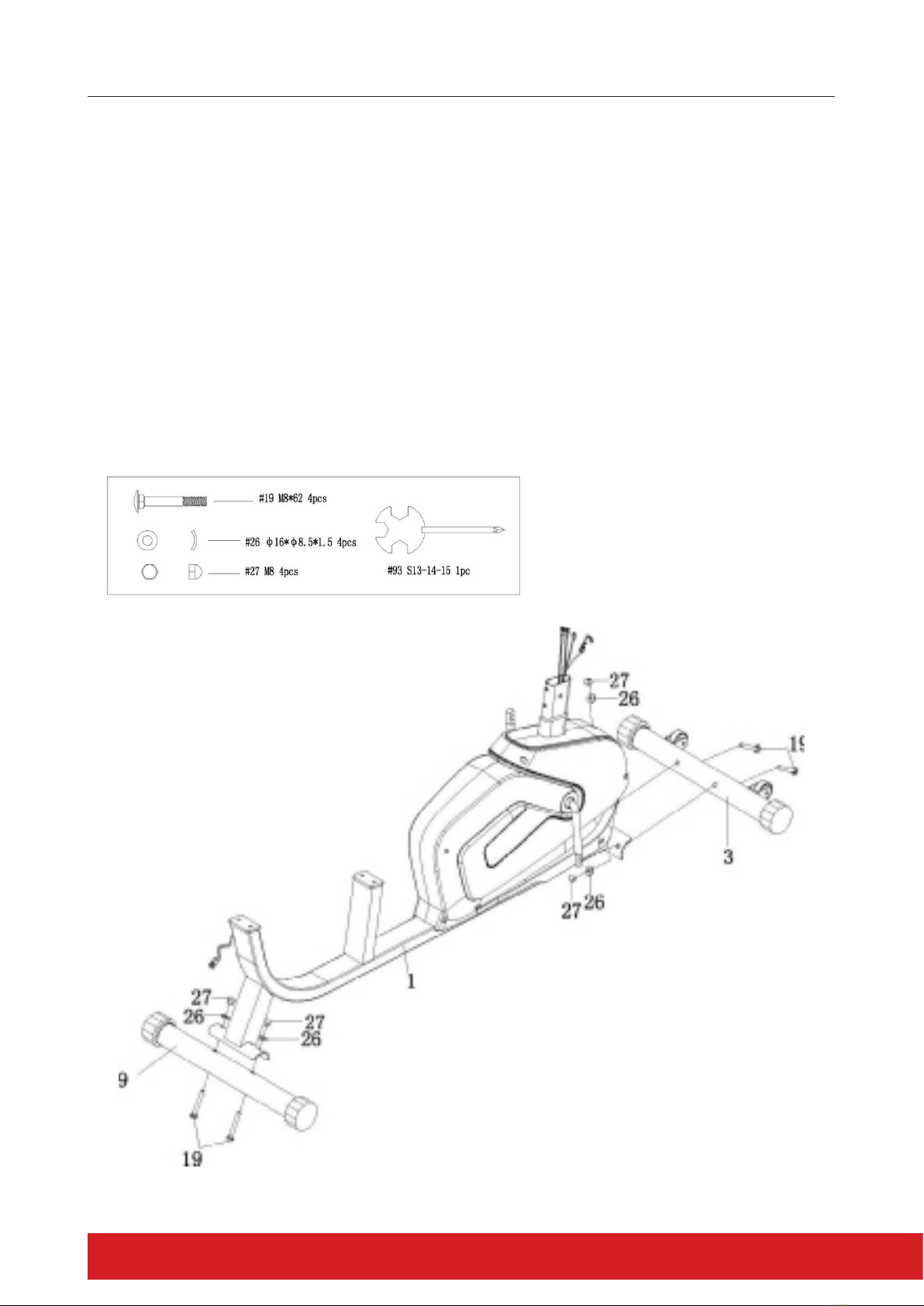
STEP 1:
Attach the Front Stabiliser (3) and the Rear Stabiliser (9) into the Main Frame (1) using a
Square Bolt (19), Arced Washer (26) and Domed Nut (27).
7ELITE VO2 EXERCYCLE ASSEMBLY MANUAL
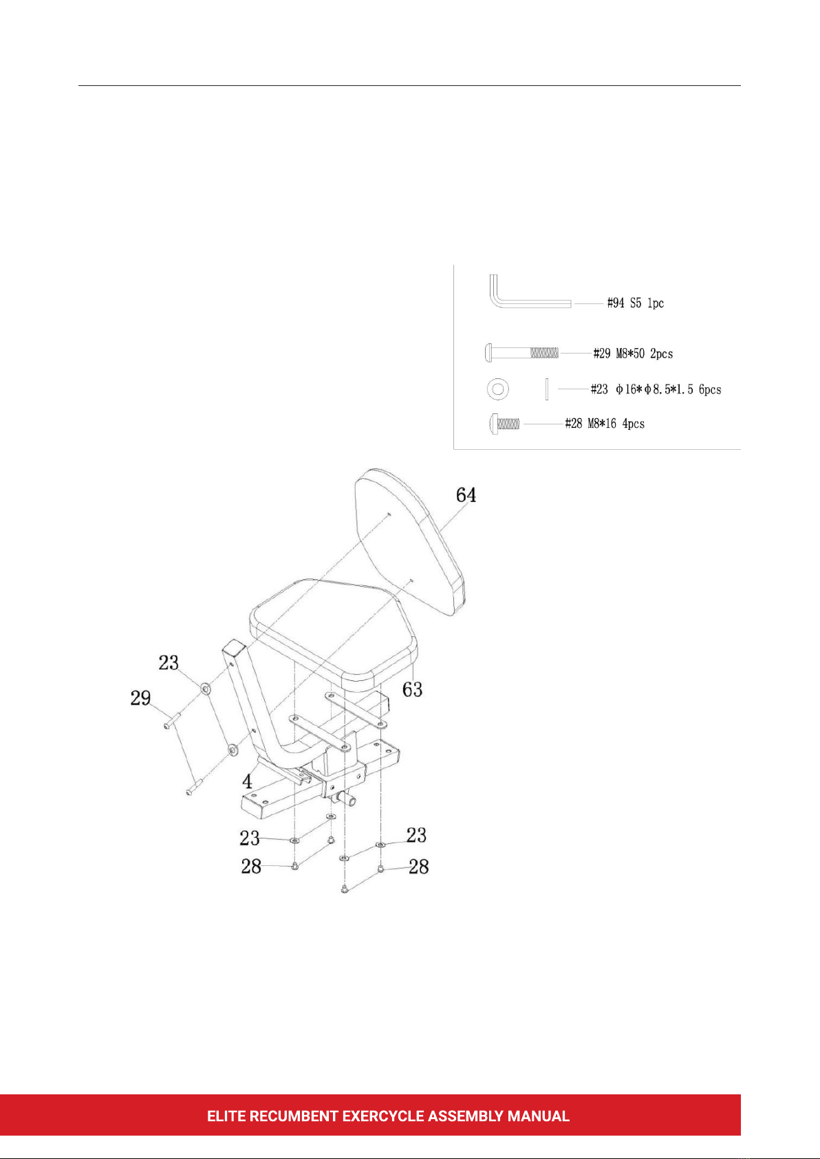
STEP 2:
Assemble the Inner Hexagon Pan Bolt (29) through Flat Washer (23) , Seat Weld (4)and Back
Cushion (64) in order and tighten firmly.
Assemble Inner Hexagon Pan Bolt (28) through Flat Washer (23) Seat Weld (4) and Seat
Cushion (63) in order and tighten firmly.
ASSEMBLY INSTRUCTIONS
8
STEP 3:
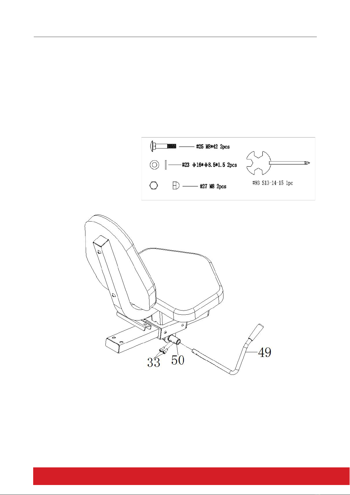
ASSEMBLY INSTRUCTIONS
1.Insert the Brake Handlebar (49) into the hole of Axle (50). Line up the hole of Brake Handlebar
(49) with hole of Axle (50) .
2. Assemble the Inner Hexagon Cylinder Screw (33) through the hole of Brake Handlebar (49) and
the hole of Axle (50) and tighten firmly.
9ELITE VO2 EXERCYCLE ASSEMBLY MANUAL
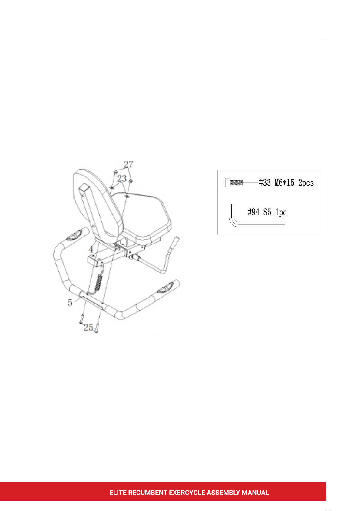
STEP 4:
Assemble the Square Bolt (25) through Handlebar Tube Weld (5) Seat Weld (4) and Flat Washer
(23), then ghten rmly using Domed Nut (27).
ASSEMBLY INSTRUCTIONS

10
STEP 5:
1. Place the Seat Weld (4) up on Main Frame (1), keeping the hole of Seat Weld (4)and the hole of
Main Frame (1) in line.
2. Assemble the Inner Hexagon Pan Bolt (22) through Spring Washer Ring (24) and Flat Washer
(23), then ghten the Adjustable Tube rmly (6). Connect Pulse Wire (80) with Pulse Mid Wire2
(82).
ASSEMBLY INSTRUCTIONS

11ELITE VO2 EXERCYCLE ASSEMBLY MANUAL
STEP 6:
1. Pull the Resistance Controller Down Wire (73) out from the hole of Upright Support(2).
2. Connect the Mid Wire1(78) with the wire of Needle Type Sensor (79).
3. Connect the Mid wire of Pulse 1 (81) with Mid wire of Pulse 2(84).
4. Insert the Upright Support (2) into Main Frame(1), keeping the hole in line and secure well using
the Hexagon Bolt (21) Arced Washer (26)and Flat Washer(23).
5. Connect the wire of Resistance Controller (72) with Resistance Controller Down Wire (73), then
lock Resistance Controller (72) into Upright Support (2) by using Crossed Pan Bolt(35) and Flat
Washer (36).
ASSEMBLY INSTRUCTIONS

12
ASSEMBLY INSTRUCTIONS
STEP 7:
1. Connect the Display Wire (77) with Pulse Mid Wire1 (78) and Mid wire2 (82).
2. Lock the Display (77) into Upright Support (2) using a Crossed Pan Bolt (37).

13ELITE VO2 EXERCYCLE ASSEMBLY MANUAL
ASSEMBLY INSTRUCTIONS
STEP 8:
Lock Pedal (60L) and Pedal (60R) simultaneously, using a Wrench(93) and tighten well.
NOTE: The Pedals (20&22) are marked “L” and “R” for Left and Right. Right foot installation is
clockwise, Left foot installation is counterclockwise. Please make sure you attach the correct pedal
to the corresponding crank. Attaching the pedal to the wrong crank can cause irreversible damage
both the pedal and the crank.
Please make sure that the nut of Pedals could be threaded through the hole on Crank well enough,
or the thread on Pedals and Cranks will be smoothed by incorrect operation.
It is a good idea to apply grease to the threads before attaching them to the crank, this will assure
that they can be removed in the future. Tighten both Pedals as firmly as possible. After using the
Exercise Bike for one week, re -ighten the Pedals. For best performance, keep the Pedals tightened.
14
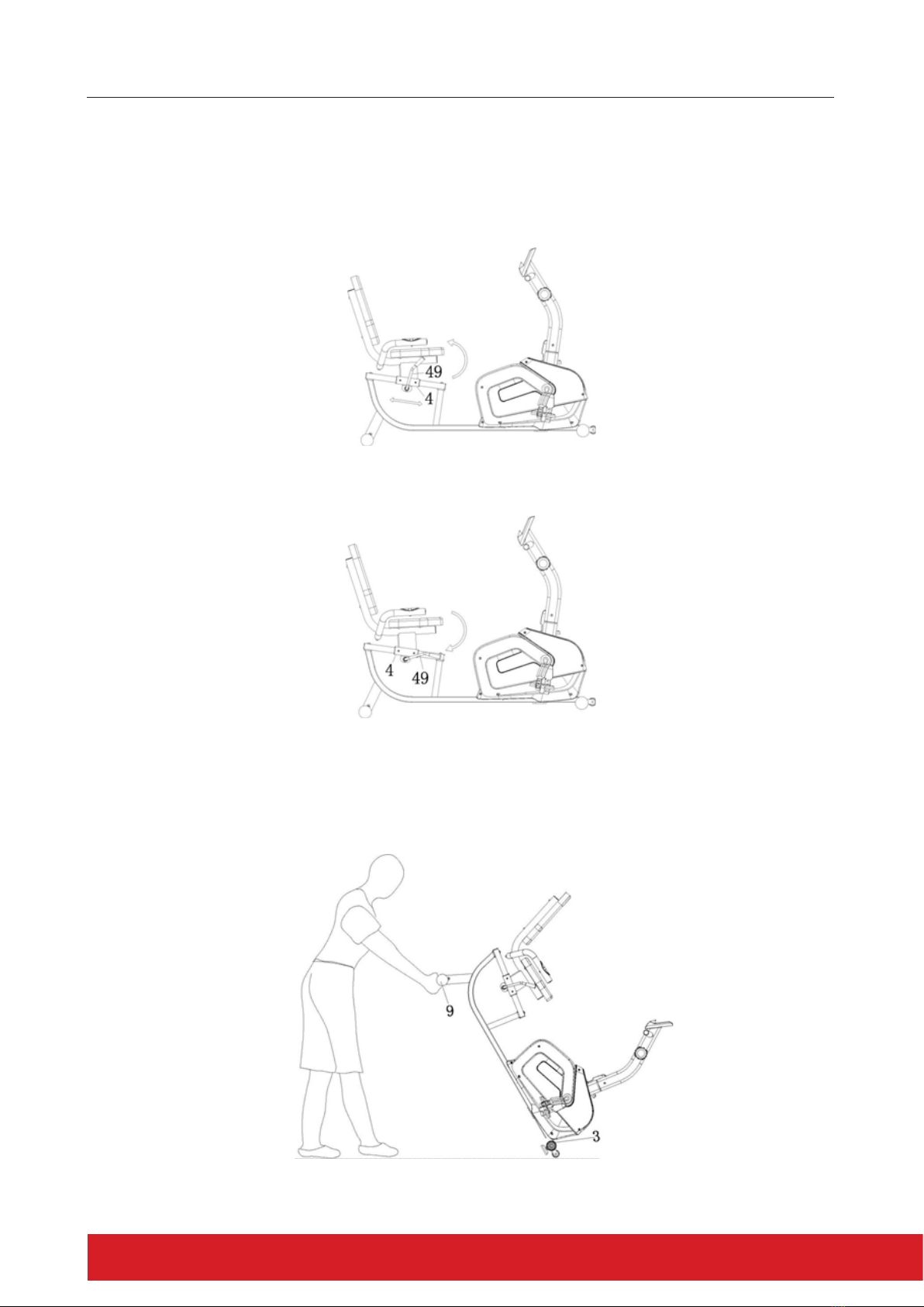
STEP 9:
1. Loosen the Brake Handlebar (49) to make the Seat (4) slidable.
2. Then, choose a suitable posion and lock the Brake Handlebar (49) in a downwards direcon to
lock the Seat (4).
ASSEMBLY INSTRUCTIONS
1
2
Moving the Bike:
Lift the front of the bike using the front wheels to transport to your desired location.

CONGRATULATIONS
Assembly of your Elite Lynx Recumbent bike is now complete! Be sure to fully inspect your
machine before using it for the rst me.
WARNING: Failure to visually check and test the assembly of your exercycle before use can cause
damage to the exercycle and injury.
16
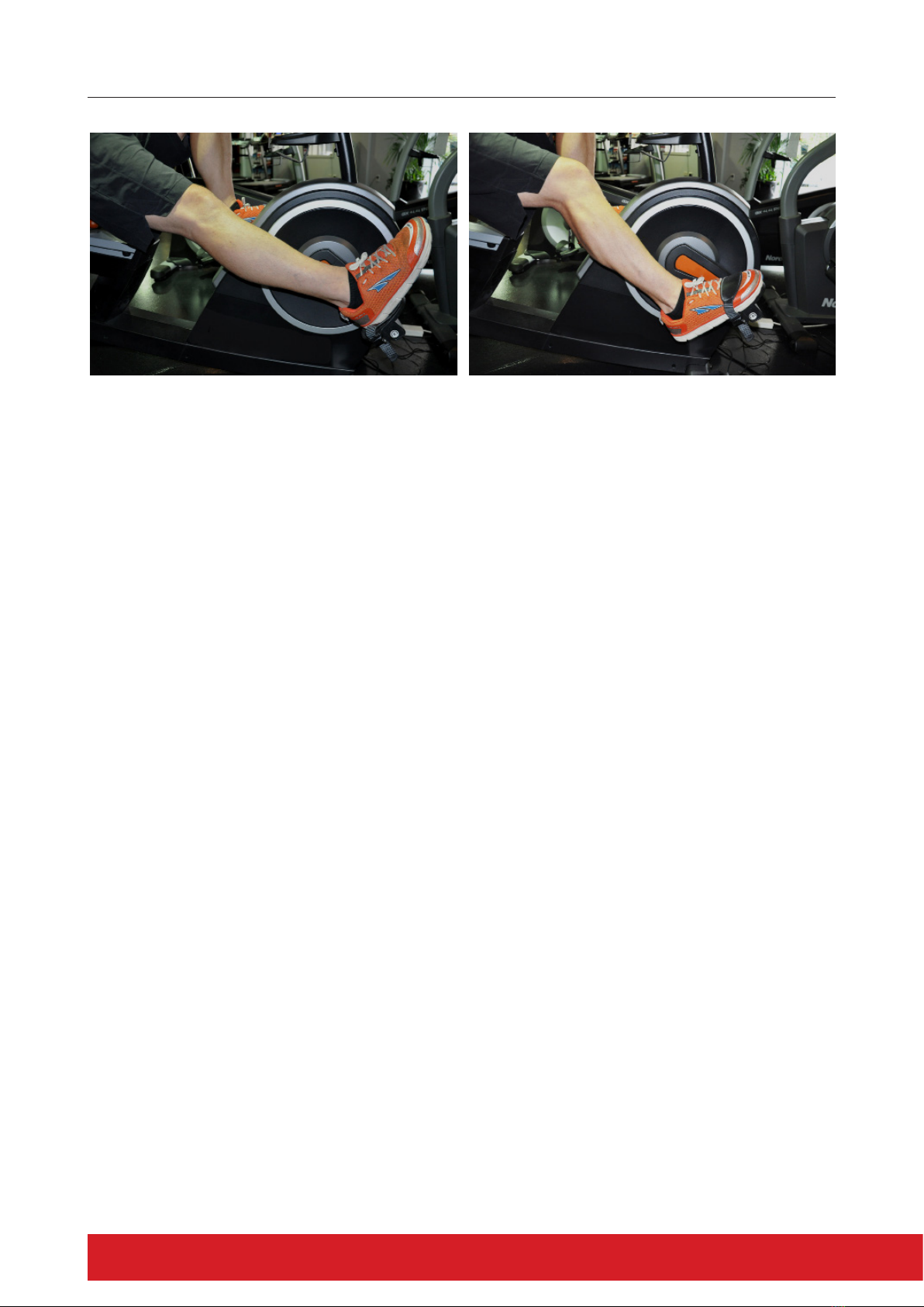
SEAT ADJUSTMENT
Seat Adjustment
Ensuring you have the most comfortable riding posion whilst minimising joint strain is important.
Adjusng your seat is simple and can normally be done without needing to get o the bike.
Place your heel on one of the bike pedals and rotate to the furthest point on the pedal stroke (as
shown) You may need to remove the toe strap to do this. If the leg is sll in the bent posion, unlock
the seat mechanism and adjust to the fully extended posion (Pic.1) – Lock the seat adjustment
mechanism in to place.
Moving your foot backwards, place your forefoot on to the pedal in the correct riding posion (Pic 2).
This should allow for a natural bend in the knee, whilst providing a full 360 degree rotaon. If you
experience the feeling of reaching for the pedal or sliding down the seat, you may need to make a
minor adjustment to the posion. Before commencing your workout please reaach and adjust the
toe strap correctly to secure your foot firmly on the pedal.
Note: If you are using the exercycle for injury rehabilitation purposes i.e. Knee Replacements you
may need to extend the seat posion further than normal to allow for any reduced joint mobility due
to swelling and inammaon.
Picture 1 – Leg extended fully with heel on pedal Picture 2 – Knee bent, forefoot on pedal

17ELITE VO2 EXERCYCLE ASSEMBLY MANUAL
DISPLAY CONSOLE

18
KEY FUNCTION:
● This key lets you to select and lock on to a parcular funcon you want.
SCAN→TIME→SPEED(SPD)→DISTANCE(DIST)→CALORIES(CAL)→TOTAL DIST→RPM→PULSE RATE
CONSOLE MONITOR INSTRUCTIONS
● Press and hold for 3 seconds to reset the value to zero(without TOTAL DIST).
SLEEP MODE:
● Sleep mode will automacally be turned on when the sensor has no signal input or no keys are
pressed for approximately 4 minutes.
FUNCTION:
1. SCAN : The display automacally changes according to the next diagram every 6 seconds. TIME
→SPEED→DISTANCE→CALORIES→TOTAL DIST→RPM→PULSE RATE
2. TIME : The total workout time.
3. SPEED: The current speed.
4. DISTANCE: The distance of each workout.
5. CALORIE: The amount of calories burnt.
6. TOTAL DIST: The distance of all the workouts. Note: if the battery is replaced, the value
returns to zero.
7. RPM: The average number of turns per minute.
8. PULSE RATE: The current pulse rate.
CONSOLE MONITOR INSTRUCTIONS
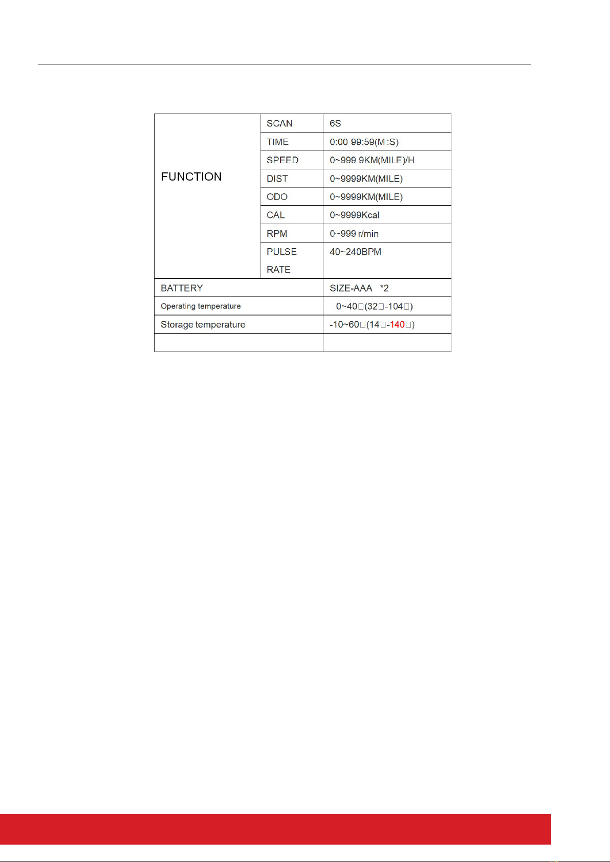
SPECIFICATIONS:
NOTE: Do not sweat onto the display window, as this may cause display excepons.

Before cleaning or carrying out any maintenance on your exercycle, ensure the power is turned o
and the power cord removed from the plug socket.
Prolong the life of your exercycle by performing periodic maintenance checks. Not only does this
ensure your machine is in full working order to ensure they connue to run smoothly and reliably,
but it will save you service costs in the long run.
Cleaning
General cleaning of the unit aer use will protect the bike’s powder-coated framework
and prevent unnecessary corrosion stains and damage to the structural components from sweat
and perspiraon.
Please ensure all sweat residue is wiped from any contact points or framework with a damp
cloth using a suitable PH neutral detergent in water to avoid salt and corrosion deposits on your
equipment. Failure or neglect to maintain and clean sweat residue from the bike frame may aect
any frame warranty implied.
Frame and Pedals
Check all nuts and bolts securing the framework, seat and handlebar assemblies are ght.
Ensure the pedals are securely aached to the crank arms. When ghtening pay aenon to the
reverse thread (ghtening an-clockwise) on the le hand pedal assembly, when sing on the
bike. Be careful not to strip or force the pedal thread when ghtening.
CARE AND MAINTENANCE
IMPORTANT INFORMATION
Table of contents
Other Elite Fitness Exercise Bike manuals

Elite Fitness
Elite Fitness Destroyer User manual

Elite Fitness
Elite Fitness WAVE ROWER User manual

Elite Fitness
Elite Fitness FALCON User manual

Elite Fitness
Elite Fitness Pursuit Air User manual

Elite Fitness
Elite Fitness DEFENDR User manual

Elite Fitness
Elite Fitness VAlOR 4 User manual

Elite Fitness
Elite Fitness RAZOR R9+ User manual

Elite Fitness
Elite Fitness Phantom User manual

Elite Fitness
Elite Fitness Slimline Series User manual

Elite Fitness
Elite Fitness VO5 User manual


