Keep Working
www.ELITETOOLS.co
10
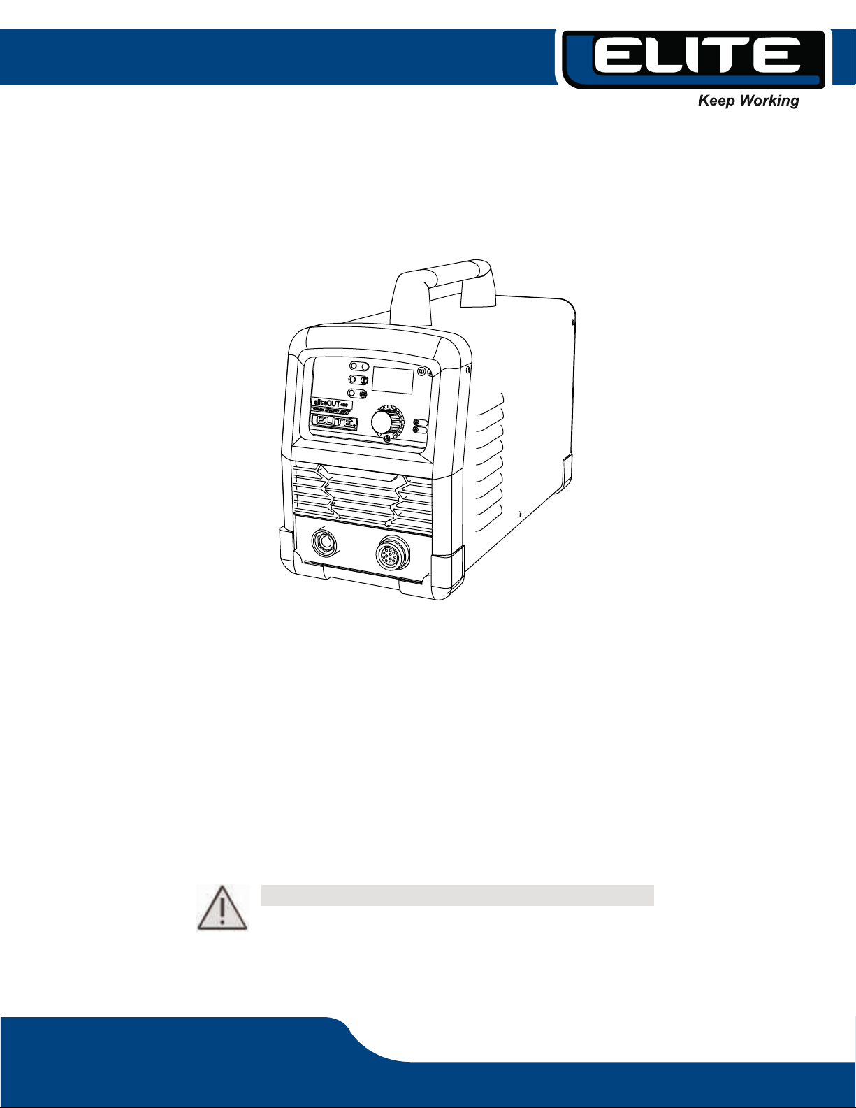
5. MACHINE CHARACTERISTICS INVERTER PLASMA CUTTER
This is a perfectly functioning, high performance and advanced technology digital plasma cutting
machine. The Elite CUT 40 S is an ultra-portable plasma cutting system suitable for a variety of
applications and requirements.
Intended for manual cutting application. The Elite CUT 40 S can cut conductive metal such as
low carbon steel, stainless steel, and aluminum.
The advanced design concept and the application of many modern technologies further protect
the user's investment.
The Elite CUT 40 S plasma cutting machine adopts international leading MUC digital intelligent
control technology, and the main parts are run through software. It is a digital control plasma
cutting machine, improved in many of its functions and performance compared to the traditional
plasma cutting machine.
Advanced digital control mode
Converts AC 50/60 Hz input voltage to DC. Through PWM technology and power IGBT modules,
the machine inverts this DC to a high voltage AC wave with a frequency of 30 to 100 KHz. The
voltage then drops and is rectified to DC output the Power Source for welding. The machine
adopts the switching inverter technology for the power supply, which greatly reduces the volume
and weight of the plasma cutter, and obviously improves the efficiency. The inverter operates at
frequencies higher than audible, which virtually eliminates noise pollution.
Advanced Inverter Technology
We generally speak of inverter machines with analog circuit control, or with analog circuits and
digital circuit control. Performance characteristics are determined by the parameters of various
components. The performance of machines differs because of these parameters, even for
machines of the same brand, their parameters often differ from each other. Also, the performan-
ce of the machine may change to some extent, as the parameters of the components may vary
depending on the environment, such as temperature and humidity, etc. One of the characteris-
tics of digital control is that it is not sensitive to changing parameters; The performance of the
machine will not be affected by changing the parameters of certain parts. Therefore, the consis-
tency and stability of the digital control cutter is better than that of the traditional cutter.
Stable performance and consistency