1000003882 (Rev. A - 03/17)
ER19_4A
Page 2
Installation
For correct and safe installation, please read these instructions completely.
• All installation work must be performed by an authorized service personnel.
• Disconnect electrical supply serving the installation area to reduce risk of electrocution.
• Unit not suitable for installations where water jets could be used.
DANGER
WARNING
• Shut off water supply serving the Installation area to reduce risk of water damage.
• Installation area must have minimum required clearances and ventilation for safe operation.
• Never wire compressor directly to electrical supply.
CAUTION
• Hose-sets are not to be used for connecting to water mains.
• Tools/Items required but not provided.
o Safety Glasses
o Protective Gloves
o Hex drives.
o Water Shut-off Valve with 3/8" (9.5mm) compression outlet.
o Fasteners for wall type.
Installation Steps
1. It is important to insure proper ventilation. Allow a minimum clearance of 12 inches (305 mm) in front and 3 inches (76mm) in the rear of the unit.
If unit is to be installed in an enclosure, allow the following clearances around unit - 1 inch (25mm) each side, 3 inches (76mm) in the rear, 3 inches
(76mm) inches above wall. If a ventilation grill is installed, the open free area must be 70 square inches or greater.
2.
3.
4.
all particles, a water strainer should be installed in the supply line.
5. Connect cooler to building supply with a shut-off valve and install a union connection between the valve and the cooler.
6. For use with photo processing applications, adjust thermostat to warmer settings.
Wiring Instructions
1. Turn off electrical supply to chiller circuit.
2. Remove Terminal Box Cover to gain access to electrical box.
3. Connect electrical supply using conduit and connectors rated to
minimum IPx1 (light rain) per local and national codes.
4. Connect ground wire to ground screw (provided).
5. Connect black wire to 220-240V 50Hz, 220-230V 60Hz, 1 phase.
6. Connect white wire to Neutral line.
7. Replace Terminal Box Cover.
Start-Up
1. Open water shut-off valve.
2. Purge air from all water lines by operating bubbler valve of
fountain to which cooler is connected. Steady water stream
assures all air is removed.
3. Rotate fan to insure proper clearance and free fan action.
4. Turn on electical supply.
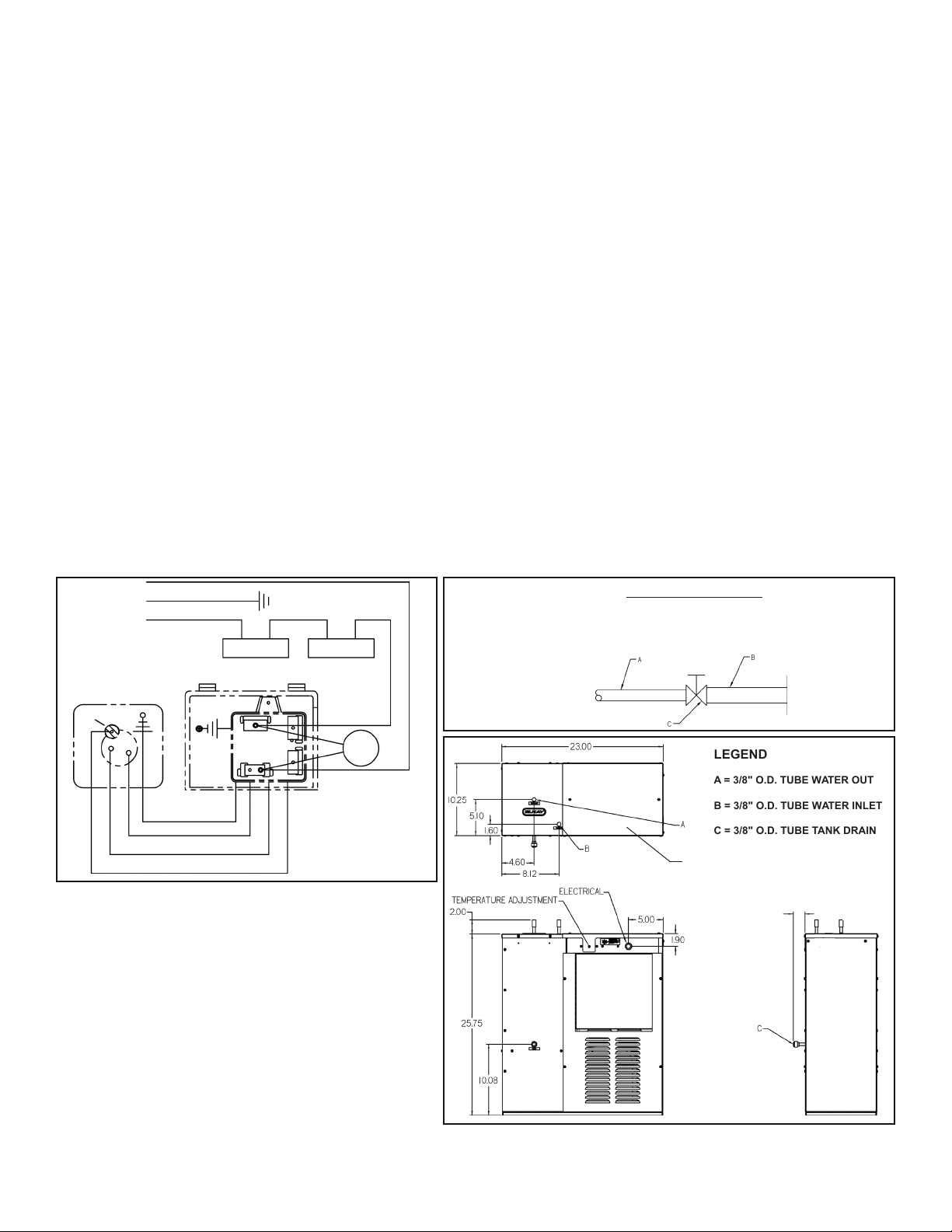
Water Mains Connection
A) 3/8” (9.5mm) O.D. Tube. Water Inlet to Chiller
B) Building Water Mains
C) Water Shut-off Valve (not provided)
LEGEND
A = 3/8" O.D. TUBE WATER OUT
B = 3/8" O.D. TUBE WATER INLET
C = 3/8" O.D. TUBE TANK DRAIN
A = Ribbed (Neutral)
B = Ground (Earth)
C = Smooth (Hot)
D = Red
E = White
F = Black
Thermostat Thermostat
Fan
CSR Box
Compressor
Overload
A
B
C
C
C
A
A
B
B
D
D
E
E
F
F
Terminal Box Cover
1.25


