manuals.online logo
Brands
  1. Home
  2. •
  3. Brands
  4. •
  5. Elkay
  6. •
  7. Water Dispenser
  8. •
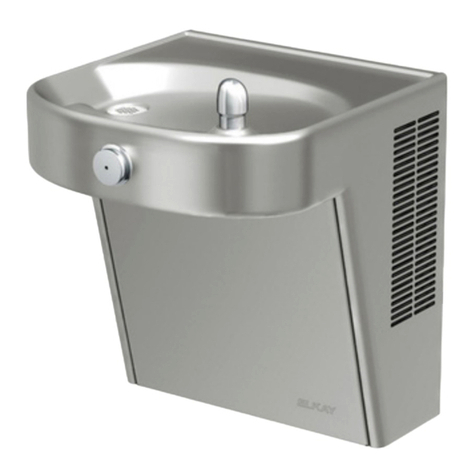
  9. Elkay VRCTLR8 1D Series Installation manual

Elkay VRCTLR8 1D Series Installation manual

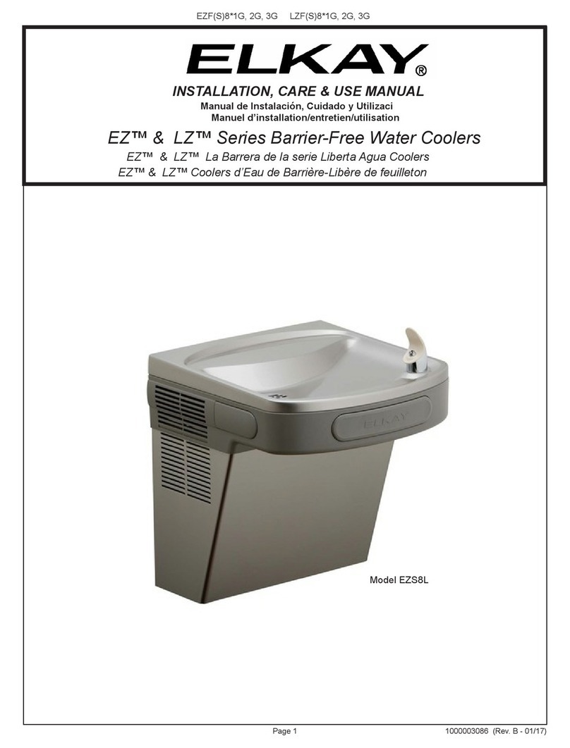
Page 1 98958C (Rev. D- 12/16)
(L)VRCTL(R)8*1D, *2C, *3C VRCDTL(R)*C (L)VRCTL(R)DD*C
Manual de Instalación, Cuidado y Utilización
Manuel d’installation/entretien/utilisation
VRCTL™ Coolers d’Eau de Barrière-Libère de feuilleton
VRCTL™ La Barrera de la serie Liberta Agua Coolers
VRCTL™ Series Barrier-Free Water Coolers
INSTALLATION, CARE & USE MANUAL
Model VRCTLR8
Model VRCTL8
(L)VRCTL(R)8*1D, *2C, *3C VRCDTL(R)*C (L)VRCTL(R)DD*C
Page 2
98958C (Rev. D - 12/16)
10
NOTE: Non-refrigerated units do not include all electrical and refrigeration components
shown above.
Other components and rough-in are the same as shown.
NOTA: Las unidades no frigoricadas no incluyen todos los componentes eléctricos y de
la refrigeración demostrados arriba. Otros componentes y a’spero-en son iguales según
lo demostrado.
NOTE: Les unités non frigoriées n’incluent pas tous les composants électriques et de
réfrigération montrés ci-dessus. D’autres composants et rugueux-dans sont identiques
que montrés.
20
22
4
16
23
1
6
6
See Fig. 4
See Fig. 6
25
25
34
21
19
11
36
35
45
45 12
21
42
40 (TL)
41 (TLR)
45 35 8
38 (TL)
39 (TLR)
29
37
21
15, 17, 18
23
6
69, 23,30
2
1
27
9, 23, 30
22
34
13
14
FIG. 1
VRCTL8 SHOWN
Uses HFC-134A refrigerant
Usa refrigerante HFC-134A
Utilise du uide frigorigéne HFC-134A
Note: Danger! Electric shock hazard. Disconnect power before servicing unit.
Nota: peligro! Peligro de descarga eléctrica. Desconecte antes de reparar la unidad.
Remarque : Danger ! Risque d'électrocution. Débrancher avant de réparer l'appareil.
50
Page 3 98958C (Rev. D- 12/16)
(L)VRCTL(R)8*1D, *2C, *3C VRCDTL(R)*C (L)VRCTL(R)DD*C
LEGEND/LEYENDA/LÉGENDE
A = RECOMMENDED WATER SUPPLY LOCATION 3/8 O.D. UNPLATED COPPER TUBE CONNECT STUB WITH SHUT OFF (BY OTHERS) 3 IN. (76mm) MAXIMUM OUT FROM WALL
La UBICACION 3/8 O RECOMENDADA de ABASTECIMIENTO DE AGUA. D. El TUBO del COBRE de UNPLATED CONECTA TALONARIO CON APAGO (POR OTROS) 3 en. (76 Mm) el MAXIMO FUERA DE
PARED
L’O.D de 3/8 d’EMPLACEMENT DE PROVISION D’EAU RECOMMANDE. LE TUBE DE CUIVRE DE UNPLATED CONNECTE STUB AVEC ETEINT (PAR LES AUTRES) 3 dans. (76 mm) le MAXIMUM HORS DU
MUR
B = RECOMMENDED LOCATION FOR WASTE OUTLET 1-1/2” O.D. DRAIN STUB 2 IN. OUT FROM WALL
UBICACIÓN RECOMENDADA PARA EL DRENAJE DE SALIDA DE AGUA, DE 1-1/2” DE DIÁMETRO. El TALONARIO 2 FUERA DE PARED
EMPLACEMENT RECOMMANDÉ POUR LE DRAIN DE D.E. 1-1/2” DE SORTIE D’EAU. STUB 2 HORS DU MUR
C = 1-1/2 TRAP NOT FURNISHED
PURGADOR DE 1-1/2 NO PROPORCIONADO
SIPHON 1-1/2 NON FOURNI
D = ELECTRICAL SUPPLY (3) WIRE RECESSED BOX
CAJA RECESIVA DE ALAMBRES (3) DE SUMINISTRO ELÉCTRICO
BOÎTE ENCASTRÉE D’ALIMENTATION ÉLECTRIQUE (3) FILS
E = INSURE PROPER VENTILATION BY MAINTAINING 6” (152 mm) (MIN.) CLEARANCE FROM CABINET LOUVERS TO WALL.
ASEGURE UNA VENTILACIÓN ADECUADA MANTENIENDO UN ESPACIO E 6” (152 mm) (MÍN.) DE HOLGURA ENTRE LA REJILLA DE VENTILACIÓN DEL MUEBLE Y LA PARED
ASSUREZ-VOUS UNE BONNE VENTILATION EN GARDANT 6” (152 mm) (MIN.) ENTRE LES ÉVENTS DE L’ENCEINTE ET LE MUR.
F = 7/16 BOLT HOLES FOR FASTENING UNIT TO WALL
AGUJEROS DE LAS TUERCAS DE 7/16 PARA SUJETAR LA UNIDAD A LA PARED
TROUS D’ÉCROUS 7/16 POUR FIXER L’APPAREIL AU MUR
FIG. 2
VRCTL8
F
D
F
E
E
2 7/16"
63mm
10"
254mm
5"
127mm
1 1/2"
38mm
A
37 1/2"
952mm
6 1/2"
166mm
ORIFICE
HEIGHT
ALTURA DEL
ORIFICIO
HAUTEUR DE
L'ORIFICE
ORIFICE
HEIGHT
ALTURA DEL
ORIFICIO
HAUTEUR DE
L'ORIFICE
C
L
C
L
1 3/8"
35mm 1 3/8"
35mm
5 3/4"
146mm 5 3/4"
146mm
1 3/8"
35mm 1 3/8"
35mm
5 3/4"
146mm 5 3/4"
146mm
18 1/16"
459mm
FINISHED FLOOR
PISO ACABADO
PLANCHER FINI
5/16" (8mm) DIA. (10 HOLES)
8mm (10 AGUJEROUS)
8mm (10 TROUS)
20 1/8"
511mm
4 1/2"
114mm
6 1/4"
159mm
18 3/4"
476mm
25 1/8"
638mm
B
3 1/2"
89mm
C
RIM HEIGHT
ALTURA DEL
ORIFICIO
HAUTEUR DE
L 'ORIFICE
18 5/8"
474mm
12 5/16"
312mm
4 3/4"
121mm
27"
686mm
31 7/8"
810mm
32 15/16"
837mm
39 1/2"
1003mm
2 5/8"
67mm
8"
203mm
13 7/8"
351mm
20 3/8"
518mm
HANGER BRACKET
FIJADOR DE SUSPENSION
SUPPORT DE SUSPENSION
*6 3/4"
173mm
* ADA REQUIREMENT
* REQUISITO DE A.D.A.
* EXIGENCE ADA
* REDUCE HEIGHT BY 3” FOR INSTALLATION OF CHILDRENS ADA COOLER
(L)VRCTL(R)8*1D, *2C, *3C VRCDTL(R)*C (L)VRCTL(R)DD*C
Page 4
98958C (Rev. D - 12/16)
13 7/8"
352mm
18 3/4"
476mm
37 1/2"
952mm
61/2"
166mm
20 3/8"
518mm
26 11/16"
677mm
31 11/16"
804mm
3 1/2"
89mm
4 1/2"
114mm
5"
127mm 10"
254mm
5 3/4"
146mm 5 3/4"
146mm
1 3/8"
35mm 1 3/8"
35mm
18 1/16"
459mm
5 3/4"
146mm 5 3/4"
146mm
1 3/8"
35mm
1 3/8"
35mm
6 1/4"
159mm
2 7/16"
63mm
1 1/2"
38mm
18 5/8"
474mm
25/8"
67mm
8"
203mm
4 3/4"
121mm
12 5/16"
312mm
27"
686mm
31 7/8"
810mm
32 15/16"
837mm
39 1/2"
1003mm
HANGER BRACKET
FIJADOR DE SUSPENSION
SUPPORT DE SUSPENSION
ORIFICE
HEIGHT
ALTURA DEL
ORIFICIO
HAUTEUR DE
L'ORIFICE
ORIFICE
HEIGHT
ALTURA DEL
ORIFICIO
HAUTEUR DE
L'ORIFICE
RIM HEIGHT
ALTURA DEL
ORIFICIO
HAUTEUR DE
L 'ORIFICE
B
D
E
E
F
F
A
C
FINISHED FLOOR
PISO ACABADO
PLANCHER FINI
5/16" (8mm) DIA. (10 HOLES)
8mm (10 AGUJEROS)
8mm (10 TROUS)
6 3/4"
173mm
LEGEND/LEYENDA/LÉGENDE
A = RECOMMENDED WATER SUPPLY LOCATION 3/8 O.D. UNPLATED COPPER TUBE CONNECT STUB WITH SHUT OFF (BY OTHERS) 3 IN. (76mm) MAXIMUM OUT FROM WALL
La UBICACION 3/8 O RECOMENDADA de ABASTECIMIENTO DE AGUA. D. El TUBO del COBRE de UNPLATED CONECTA TALONARIO CON APAGO (POR OTROS) 3 en. (76 Mm) el MAXIMO FUERA DE
PARED
L’O.D de 3/8 d’EMPLACEMENT DE PROVISION D’EAU RECOMMANDE. LE TUBE DE CUIVRE DE UNPLATED CONNECTE STUB AVEC ETEINT (PAR LES AUTRES) 3 dans. (76 mm) le MAXIMUM HORS DU
MUR
B = RECOMMENDED LOCATION FOR WASTE OUTLET 1-1/2” O.D. DRAIN STUB 2 IN. OUT FROM WALL
UBICACIÓN RECOMENDADA PARA EL DRENAJE DE SALIDA DE AGUA, DE 1-1/2” DE DIÁMETRO. El TALONARIO 2 FUERA DE PARED
EMPLACEMENT RECOMMANDÉ POUR LE DRAIN DE D.E. 1-1/2” DE SORTIE D’EAU. STUB 2 HORS DU MUR
C = 1-1/2 TRAP NOT FURNISHED
PURGADOR DE 1-1/2 NO PROPORCIONADO
SIPHON 1-1/2 NON FOURNI
D = ELECTRICAL SUPPLY (3) WIRE RECESSED BOX
CAJA RECESIVA DE ALAMBRES (3) DE SUMINISTRO ELÉCTRICO
BOÎTE ENCASTRÉE D’ALIMENTATION ÉLECTRIQUE (3) FILS
E = INSURE PROPER VENTILATION BY MAINTAINING 6” (152 mm) (MIN.) CLEARANCE FROM CABINET LOUVERS TO WALL.
ASEGURE UNA VENTILACIÓN ADECUADA MANTENIENDO UN ESPACIO E 6” (152 mm) (MÍN.) DE HOLGURA ENTRE LA REJILLA DE VENTILACIÓN DEL MUEBLE Y LA PARED
ASSUREZ-VOUS UNE BONNE VENTILATION EN GARDANT 6” (152 mm) (MIN.) ENTRE LES ÉVENTS DE L’ENCEINTE ET LE MUR.
F = 7/16 BOLT HOLES FOR FASTENING UNIT TO WALL
AGUJEROS DE LAS TUERCAS DE 7/16 PARA SUJETAR LA UNIDAD A LA PARED
TROUS D’ÉCROUS 7/16 POUR FIXER L’APPAREIL AU MUR
* REDUCE HEIGHT BY 3” FOR INSTALLATION OF CHILDRENS ADA COOLER
FIG. 3
VRCTLR8
* ADA REQUIREMENT
* REQUISITO DE A.D.A.
* EXIGENCE ADA
Page 5 98958C (Rev. D- 12/16)
(L)VRCTL(R)8*1D, *2C, *3C VRCDTL(R)*C (L)VRCTL(R)DD*C
IMPORTANT
ALL SERVICE TO BE PERFORMED BY AN
AUTHORIZED SERVICE PERSON
IMPORTANTE
TODO EL SERVICIO DEBERÁ SER EFECTUADO POR UNA
PERSONA DE SERVICIO AUTORIZADA
INSTALLATION DU SIPHON ET DU
SUPPORT DE SUSPENSION
1) Retirez le support de suspension à l’arrière du refroidis-
seur en enlevant une (1) vis.
2) Installez le support et le siphon tel qu’indiqué à la g. 2
ou 3.
NOTE : Le support de suspension DOIT être bien retenu en
place. Ajoutez des ferrures de xation si le mur n’offre
pas le soutien voulu.
IMPORTANT :
• Pour avoir une bonne position, on doit garder une
dimension de 4 3/4 po. (121mm) du mur à l’axe central
du siphon.
• Ancrez solidement le support au mur à l’aide des ve
(5) trous de xation d’un diam. 1/4 po.
3) Installez la soupape droite dans le tuyau de D.E. 3/8”.
HANGER BRACKETS & TRAP
INSTALLATION
1) Remove hanger bracket fastened to back of
cooler by removing one (1) screw.
2) Mount the hanger bracket and trap as shown
in Figure 2 or 3.
NOTE: Hanger Bracket MUST be supported
securely. Add xture support carrier if wall will
not provide adequate support.
IMPORTANT:
 4 3/4 in. (121mm) dimension from wall to cen-
terline of trap must be maintained for proper t.
 Anchor hanger securely to wall using all ve
(5) 1/4 in. dia. mounting holes.
3) Install straight valve for 3/8” O.D. tube.
INSTALACIÓN DE FIJADOR DE
SUSPENSIÓN Y DEL PURGADOR
1) Quite el jador de suspensión sujetados a la parte posterior del
enfriador quitando un (1) tornillo.
2) Monte el jador de suspensión y quite el purgador como se
muestra en la Fig. 2 o 3.
NOTA: El jador de suspensión DEBE de ser sostenido con seguri-
dad. Coloque portadores de soporte de instalaciones jas si la
pared no proveerá un soporte adecuado.
IMPORTANTE:
• Se debe mantener una dimensión de 4 3/4 pulgadas (121mm)
desde la pared hasta la línea central del purgador para que
calce de forma adecuada.
•Ancle el suspensor de forma segura a la pared usando todos
los cinco (5) agujeros de montaje de 1/4” de diámetro.
3) Instale la válvula directa para el tubo de 3/8” de diámetro externo.
INSTALLATION OF COOLER
4) Hang the cooler on the hanger bracket. Be
certain the hanger bracket is engaged properly
in the slots on the cooler back as shown in Figure
2 or 3.
5) Loosen the two (2) screws holding the lower
front panel at the bottom of cooler base and
two (2) screws at the top (Use torx bits sold
separately). Remove the front panel and set
aside.
6) Connect water inlet line--See Note 4 of General
Instructions.
7) Remove the slip nut and gasket from the trap
and install them on the cooler waste line mak-
ing sure that the end of the waste line ts into
the trap. Assemble the slip nut and gasket to
the trap and tighten securely.
INSTALACIÓN DEL ENFRIADOR DE AGUA
4) Suspenda el enfriador en el jador de suspensión. Asegúrese
que el jador de suspensión calce correctamente en las ranuras
de la parte posterior del enfriador como se indica en la gura 2
o 3.
5) Aoje los dos (2) tornillos que sostienen la parte inferior del panel
en la parte inferior de la base del enfriador y los dos (2) tornillos
en la parte superior (Utilice los pedacitos torx vendidos por
separado). Quite el panel frontal y póngalo a un lado.
6) Conectar el tubo de entrada de agua. Ver la Nota 4 en las
Instrucciones Generales.
7) Saque la tuerca deslizante y empaquetadura del colector e ins-
tálelos en la manquera de residous de la nevera, asequrándose
que el extremo de la manquera encaje en el colector. Coloque
la tuerca deslizante y la empaquetadura en el colector y apriete
rmermente.
INSTALLATION DU REFROIDISSEUR
4) Installez le refroidisseur sur le support en vous assurant
que ceux-ci sont bien installés dans les fentes à l’arrière
du refroidisseur tel qu’indiqué à la gure 2 ou 3.
5) Dégagez les deux (2) vis retenant le panneau inférieur
avant au bas de la base du refroidisseur ainsi que deux
(2) vis sur le dessus (Employez le peu Torx vendu
séparément). Retirez le panneau avant et mettez-le
de côté.
6) Connectez l’alimentation en eau. - Voir note 4 des
instructions générales.
7) Retirez l’écrou coulissant et le joint du siphon et les
installer sur la conduite de vidange de la fontaine en
s’assurant que l’extrémité de la conduite de vidange
s’ajuste dans le siphon. Assembler l’écrou coulissant
et le joint sur le siphon et srrer fermement.
PUESTA EN MARCHA
Ver también las Instrucciones Generales
8) La altura del chorro se ajusta en la fábrica a 45-50 PSI. Si la
presión de suministro varía mucho de esta valor, ajustar el tornillo
usar el agujero de acceso en el botón. El ajuste en sentido
horario elvará el chorro y en sentido contrahorario lo bajará
(inserte el destornillador). Para un ajuste mejor, el chorro debe
chocar con el depósito aproximadamente a
6-1/2”(165mm) del borboteador.
START UP
Also See General Instructions
8) Stream height is factory set at 45-50 PSI. If
supply pressure varies greatly from this, adjust
screw using the access hole in the pushbutton
(insert screwdriver). CW adjustment will raise
stream and CCW adjustment will lower stream.
For best adjustment, stream should hit basin
approximately 6-1/2” (165mm) from bubbler.
MISE EN MARCHE
Voir aussi les Instructions Générales
8) La pression du jet est réglée en usine 3,1 et 3,4 bars.
Si la pression d’alimentation varie fortement de cette
valeur employer l’ouverture d’accès dans le bouton-
poussoir. Un réglage dans le sens des aiguilles d’une
montre relève le jet, et un réglage dans le sens con-
traire l’abaisse (insérez le tournevis). Pour un réglage
optimum, le jet doit frapper le bassin à environ 165
mm du barboteur.
IMPORTANT
TOUT ENTRETIEN DOIT ÊTRE EFFECTUÉ PAR UN
REPRÉSENTANT AUTORISÉ

This manual suits for next models

20

Other Elkay Water Dispenser manuals

Elkay EFHA14 1J Series Installation manual

Elkay

Elkay EFHA14 1J Series Installation manual

Elkay EZH2O EZSTLG8WS 1B Series Instructions for use

Elkay

Elkay EZH2O EZSTLG8WS 1B Series Instructions for use

Elkay EZH20 LZWSMD* Installation manual

Elkay

Elkay EZH20 LZWSMD* Installation manual

Elkay VRCTL Series Installation manual

Elkay

Elkay VRCTL Series Installation manual

Elkay EZTL Series Installation manual

Elkay

Elkay EZTL Series Installation manual

Elkay DSWH160UVPC Manual

Elkay

Elkay DSWH160UVPC Manual

Elkay EZSTL8WS 1G Series Instructions for use

Elkay

Elkay EZSTL8WS 1G Series Instructions for use

Elkay ezH2O LZWSM8 Series Installation manual

Elkay

Elkay ezH2O LZWSM8 Series Installation manual

Elkay LZ Series Installation manual

Elkay

Elkay LZ Series Installation manual

Elkay LMABF-BAC Series Installation manual

Elkay

Elkay LMABF-BAC Series Installation manual

Elkay Space-ette FHD70052EJO Series Installation manual

Elkay

Elkay Space-ette FHD70052EJO Series Installation manual

Elkay ESRC8 1G Series Installation manual

Elkay

Elkay ESRC8 1G Series Installation manual

Elkay VRC8 1A Series Installation manual

Elkay

Elkay VRC8 1A Series Installation manual

Elkay ERPB8C 3C Series Installation manual

Elkay

Elkay ERPB8C 3C Series Installation manual

Elkay ESR3100D-A Instruction Manual

Elkay

Elkay ESR3100D-A Instruction Manual

Elkay DSBWCT5G Installation manual

Elkay

Elkay DSBWCT5G Installation manual

Elkay EZSDWS 1G Series Instructions for use

Elkay

Elkay EZSDWS 1G Series Instructions for use

Elkay ezH2O LBWD06BKK User manual

Elkay

Elkay ezH2O LBWD06BKK User manual

Elkay OBFATL8 1E Series Installation manual

Elkay

Elkay OBFATL8 1E Series Installation manual

Elkay EMABF8WS*1D Series Instructions for use

Elkay

Elkay EMABF8WS*1D Series Instructions for use

Elkay EMABFD B Series Instructions for use

Elkay

Elkay EMABFD B Series Instructions for use

Elkay VRC8WS Installation manual

Elkay

Elkay VRC8WS Installation manual

Elkay HEW1 1J Series Installation manual

Elkay

Elkay HEW1 1J Series Installation manual

Elkay ESWA8 1G Series Installation manual

Elkay

Elkay ESWA8 1G Series Installation manual

Popular Water Dispenser manuals by other brands

IBC Water AST0715MP-960 Installation & operating instructions

IBC Water

IBC Water AST0715MP-960 Installation & operating instructions

Lancaster Water Treatment X FACTOR LX15 Series Installation, operating and service manual

Lancaster Water Treatment

Lancaster Water Treatment X FACTOR LX15 Series Installation, operating and service manual

Oasis Osmosis Home installation manual

Oasis

Oasis Osmosis Home installation manual

Monarch Water ULTIMATE MINI AQUA HE install guide

Monarch Water

Monarch Water ULTIMATE MINI AQUA HE install guide

Haier HLM-109B instruction manual

Haier

Haier HLM-109B instruction manual

GE GXOF18G Owner's manual and installation instructions

GE

GE GXOF18G Owner's manual and installation instructions

Kenmore 625.385560 UltraFilter 650 owner's manual

Kenmore

Kenmore 625.385560 UltraFilter 650 owner's manual

Aries Hydra DI Operation & maintenance manual

Aries

Aries Hydra DI Operation & maintenance manual

Avanti WD31EC instruction manual

Avanti

Avanti WD31EC instruction manual

GE GNCF02H owner's manual

GE

GE GNCF02H owner's manual

Avanti WD360 instruction manual

Avanti

Avanti WD360 instruction manual

ProFlo PFB Series Installation & operation manual

ProFlo

ProFlo PFB Series Installation & operation manual

Frakco Travelsoft RV 2400HD Operation instructions

Frakco

Frakco Travelsoft RV 2400HD Operation instructions

Aqua Essentials Borg & Overström B4 user guide

Aqua Essentials

Aqua Essentials Borg & Overström B4 user guide

KENT 11063 Instruction handbook

KENT

KENT 11063 Instruction handbook

Calmat Plus user manual

Calmat

Calmat Plus user manual

Igloo MWC529 instruction manual

Igloo

Igloo MWC529 instruction manual

Electrolux EQALF01TXSP user manual

Electrolux

Electrolux EQALF01TXSP user manual

manuals.online logo
manuals.online logoBrands
  • About & Mission
  • Contact us
  • Privacy Policy
  • Terms and Conditions

Copyright 2025 Manuals.Online. All Rights Reserved.