manuals.online logo
Brands
  1. Home
  2. •
  3. Brands
  4. •
  5. Elko
  6. •
  7. Accessories
  8. •
  9. Elko Inels Air AirQS-100NB User manual

Elko Inels Air AirQS-100NB User manual

1 / 4
L N
AirQS-100NB
02-60/2019 Rev.: 0
1
3
1
1
6
55
55
4
2
2
2
2
L N
7
8
4
a)
b)
3L N
L
N
12
ELKO EP, s.r.o.
Palackého 493
769 01 Holešov, Všetuly
Czech Republic
Tel.: +420 573 514 211
e-mail: [email protected]
www.elkoep.com
Characteristics
Description
EN
Made in Czech Republic
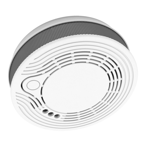
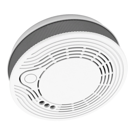
• AirQS-100 - monitors the CO2content of the room and also measures the actual
temperature, humidity and light intensity in the room.
• Anti-sabotage: If access to the device is unauthorized, a message is immediately
sent to the server.
• Thanks to the wireless solution and NB-IoT communication, it can communicate
instantly to your chosen location and be operated immediately.
• Data is sent to the server from which it can be subsequently displayed as a smart-
phone, application, or Cloud notication.
• Power supply 110-240 V AC.
General instrucions
1. Two-color LED position
2. Holes for locking segments
3. Supply voltage terminal
4. Tamper position
5. Secure segments
6. Probe for magnet scanning
tampermenty
7. Button SET
8. NanoSIM slot
The underside of
the detector
Cloud app assignment
It is done in your Smartphone application. Enter the relevant data located on the detec-
tor cover into the application.
The inner side of
the base
The front of the
detector
Air quality sensor - carbon dioxide (CO2)
Internet of Things (IoT)
• The IOT wireless communications category describes the Low Power Wide Area
(LPWA). This technology is designed to provide full-range coverage both inside and
outside buildings, energy-saving and low-cost operation of individual devices. The
NarrowBand network is available to use this standard.
Information about the NarrowBand network
• The network provides two-way communication and the only one to use the licensed
LTE band. Our devices allow band 1 (2100MHz), Band 3 (1800MHz), Band 8 (900MHz),
Band 5 (850MHz), Band 20 (800MHz) and Band 28 (700MHz).
• It uses this SIM card technology for each device.
• The advantage of NarrowBand is the use of already built-up grids, which ensures suf-
cient reception outside and inside buildings.
• For more information on this technology, please visit www.vodafone.cz
Caution for proper operation:
• Products are installed according to the wiring diagram given for each product.
• For proper device functionality, it is necessary to have sucient coverage of the se-
lected network at the installation site.
• At the same time, the device must be registered in the network. Successful device reg-
istration on a given network requires a charge for trac.
• Each network oers dierent tari options - it always depends on the number of mes-
sages you want to send from your device. Information on these taris can be found in
the current version of the ELKO EP pricelist.
Assembly
1. Place the base at the desired location (on a at surface) so that the power supply is lo-
cated in the centre opening. You can use the base as a drilling template. Attach the base
with suitable bonding material * according to the substrate.
2. Carefully insert nanoSIM (the device must not be energized when inserting or replacing
nanoSIM!)
3. Connect the supply voltage to the detector clamp (by attaching the supply voltage, the
detector functionality message will be sent to the application).
4. Adjust the connected wire and place the detector on the base so that the projection
on the base faces the tamper position in the detector cover (a). Turn the detector clock-
wise (b).
* Suitable tting material can be, for example, a countersunk head screw, a screw Ø of
3 mm.
2 / 4
Function
The detector detects the carbon dioxide (CO2) content in conned spaces by means of a
sensor. Sending a message to the server alerts you to the need air the space
Indications and states of the detector:
After the power supply is connected, the detector sends an introductory message con-
taining the measured values of of temperature, light intensity, humidity, CO2level and
rmware version of the device.
• Sends a data message about the measured values and the status of the detector every
10 minutes.
• Indication of measured CO2concentration
- the green LED blinks briey - the measured values are OK.
- Red LED blinks briey - CO2concentration is higher than 1500 ppm.
Air quality is undesirable. It is necessary to air the room.
• Supply voltage indication
- The green LED is lit under the button.
• Removed from base:
- sending a message to the server.
- every 2 seconds the red LED on the detector blinks.
Placement recommendations
• The detector is intended for indoor use. Therefore, use it exclusively for scanning in
closed, dry and dust-free areas.
• Ensure that the ventilation openings remain free and do not block it with other appli-
ances, furniture or other objects.
• Place the detector in such a place that the ambient air can ow through the device.
• If a solid object or liquid enters the detector’s interior, immediately suspend its operation
and disconnect it from the power supply!
Appropriate location
• Carbon dioxide is heavier than air. The best location for determining the average CO2
concentration is about 1.6 m above the oor.
• The detector should be placed in the bedrooms and rooms where you regularly spend
time (oces, classrooms ...).
Inappropriate location
• In areas with limited air circulation e.g.: vestibule, niches, etc.
• In places where there is a sudden change in temperature or humidity.
• Where condensation occurs.
• In close proximity to windows, doors, ventilation devices.
• In direct proximity to persons or animals.
• In direct sunlight or near a heat source.
To ensure proper operation, it is advisable to keep the detector clean
• At least once every 6 months, clean the surface using a soft brush or cloth. Using a brush-
less vacuum cleaner, carefully clear the cover and the ventilation holes from dust and
dirt.
• Never use water, detergents or solvents. The detector may be damaged.
• Do not use any chemicals near the device (such as cleaning products, hair spray ...) fumes
can adversely affect the function of the device.
• Do not apply colour to the detector. When painting, remove the detector and return to
the location after the work has finished.
• Do not disassemble the detector; do not attempt to clean the inside of the detector.
Maintenance and cleaning
Important Notice
• The detector can only warn you in time if it is properly installed and properly main-
tained and tested according to the instructions.
• Note that the correct indication of CO2concentration depends on how the air in the
room is mixed, i.e. it takes a few minutes for the CO2concentration to stabilize.
• The detector is not suitable as a measuring instrument or part of a device to alert in the
presence of gas, smoke or exhaust gases, or as part of a re alarm or similar security
device.
• The detector is not intended for installation in an industrial environment.
• Always be aware of potential dangers, develop safety awareness, and take precautions
to avoid dangers whenever and wherever needed. The detector can reduce the likeli-
hood of catastrophe but cannot guarantee 100% safety.
Information about carbon dioxide (CO2)
Carbon dioxide is a colourless gas without taste and odour; at higher concentrations you
can have a slightly sour taste in your mouth. It‘s not burning, it‘s not poisonous - it asphyxi-
ates.
The CO2concentration in the air is measured in ppm (parts per million). Under normal
conditions, carbon dioxide in the air is represented by 0.04% (ca. 350-400 ppm), the hu-
man body does not respond to this quantity. The recommended indoor CO2level is about
1000 ppm.With increased CO2concentration in the air (1200-1,500 ppm), there are fatigue,
headache, and performance decreases. The reaction to the amount of carbon dioxide in
the air is subjective, aecting, for example, the state of health, temperature and humidity.
As the maximum concentration without health risks the value is up to 5000 ppm. Higher
levels of nausea, increased heartbeat, breathing diculties, unconsciousness, and life-
threatening conditions can occur.
3 / 4
UPLINK
Function
Byte 0-14 15 16 17 18 19 20 21 22 23 24 25 26
Bit 7-4 3 2 1 0
START
IMEI
0xC
Tamper:
1 - opened
0 - close
reserved reserved
Alarm:
1 - alarm
0 - OK
FW version reserved reserved
Temperature [0]
Temperature [1]
Humidity [0]
Humidity [1]
Illuminance [0]
Illuminance [1]
CO2[0]
CO2[1]
HEARTBEAT 0x0 0x00
Run
time[0]
Run
time[1]
ALARM 0x6 0x00
Notes
Unit Example
Temperature [°C] * 10 00F5 = 245 = 24,5 °C
Humidity [%] *10 01A1 = 417 = 41,7 %
Example
Message example Byte
04 00 00 48 00 54 01 25 04 Message type and ags - rst digit dene message type according to the table ( 0 is heartbeat ) and second digit
dene ags of battery, tamper and smoke alarm - 4 Hex is 0100 binary so according to the table the battery is low
00 Value according to the message type - in this case message type is Heartbeat so byte don´t have useful value
00 Run time in hours - 0 * 256 hours
48 Run time in hours - 48 Hex is 72 decimaly so the run time is 72 hours
00
Temperature - 0054 Hex is 84 decimaly so the temperature is 8.4 °C
54
01
Humidity - 0125 Hex is 293 decimaly so the humidity is 29.3 %
25
4 / 4
AirQS-100NB
Warning
Read the operating instructions before installing the device and putting it into opera-
tion. Instruction manual is designated for mounting and also for user of the device. It is
always a part of its packing. Installation and connection can be carried out only by a per-
son with adequate professional qualication upon understanding this instruction man-
ual and functions of the device, and while observing all valid regulations. Trouble-free
function of the device also depends on transportation, storing and handling. In case you
notice any sign of damage, deformation, malfunction or missing part, do not install this
device and return it to its seller. It is necessary to treat this product and its parts as elec-
tronic waste after its lifetime is terminated. Before starting installation, make sure that all
wires, connected parts or terminals are de-energized. While mounting and servicing ob-
serve safety regulations, norms, directives and professional, and export regulations for
working with electrical devices. Do not touch parts of the device that are energized – life
threat. To ensure the transmission of the radio signal, make sure that the devices in the
building where the installation is installed are correctly located. Unless otherwise stated,
the devices are not intended for installation in outdoor and damp areas, they must not
be installed in metal switchboards or in plastic cabinets with metal doors - this prevents
transmission of the radio frequency signal. iNELS Air is not recommended for control-
ling life-saving instruments or for controlling hazardous devices such as pumps, heaters
without thermostat, lifts, hoists, etc. - radio frequency transmission may be overshad-
owed by obstruction, interference, transmitter battery may be discharged etc., thereby
disabling the remote control.
Technical parameters
* Multiple frequency bands of B1 / B3 / B5 / B8 / B20 / B28
** Depending on network coverage
Power supply
External power supply:
Input
Measurement of CO2concentration:
Sensitivity:
Accuracy:
Temperature measuring:
Sensitivity:
Accuracy:
Humidity measuring:
Sensitivity:
Accuracy:
Light intensity measurement:
Range:
Setting
Alarm Detection:
Indication
Red / green LED:
Detection area:
Recommended installation height:
Communication
Protocol:
Transmitter frequency:
Range in open space:
Transmission power (max.):
Other parameters
Working temperature:
Storage temperature:
Operation position:
Mounting:
Protection degree:
Color:
Dimension:
Weight:
110 - 240 V AC
YES
300 - 5 000 ppm
5% (0 - 180 ppm)
built-in sensor
-25 .. 70 °C
± 3 °C
built-in sensor
0 .. 90 % RH
± 4 %
built-in sensor
0.045 - 188 000 Lx
message to the server
See manual
max. 40 m3
max. 4 m
NB-IoT
LTE Cat NB1*
Approx. 30 km**
200 mW / 23 dBm
0…+40 °C
-30…+70 °C
Horizontal (ceiling) / Vertical (Wall)
screws
IP20
white
Ø 120 x 36 mm
185 g
The company ELKO EP, as the manufacturer, is entitled to make technical modications to the
product, in the technical specication and product manual, without prior notication.

This manual suits for next models

1

Other Elko Accessories manuals

Elko DCL User manual

Elko

Elko DCL User manual

Elko inels RFDSC-71 User manual

Elko

Elko inels RFDSC-71 User manual

Elko inelsAir AirSOU-100NB User manual

Elko

Elko inelsAir AirSOU-100NB User manual

Elko Inels RFSC-11 User manual

Elko

Elko Inels RFSC-11 User manual

Elko INELS Air Series User manual

Elko

Elko INELS Air Series User manual

Elko SmartDim Puck Uni User manual

Elko

Elko SmartDim Puck Uni User manual

Elko inels RFDSC-11 User manual

Elko

Elko inels RFDSC-11 User manual

Elko AirMD-100NB User manual

Elko

Elko AirMD-100NB User manual

Elko iNELS Air AirQS-101 User manual

Elko

Elko iNELS Air AirQS-101 User manual

Elko iNELS Air AirSOU-100S User manual

Elko

Elko iNELS Air AirSOU-100S User manual

Elko INELS RF Control RFSC-61 User manual

Elko

Elko INELS RF Control RFSC-61 User manual

Elko iNELS Air AirCFS-100NB User manual

Elko

Elko iNELS Air AirCFS-100NB User manual

Elko Inels RFDSC-71 User manual

Elko

Elko Inels RFDSC-71 User manual

Elko Inels Air AirQS-101NB User manual

Elko

Elko Inels Air AirQS-101NB User manual

Elko iNels RFSC-11 User manual

Elko

Elko iNels RFSC-11 User manual

Elko iNels RFDSC-71N User manual

Elko

Elko iNels RFDSC-71N User manual

Elko iNels RFSC-61N User manual

Elko

Elko iNels RFSC-61N User manual

Elko Inels AirQS-101S User manual

Elko

Elko Inels AirQS-101S User manual

Elko SmartSensor Leakage Wireless User manual

Elko

Elko SmartSensor Leakage Wireless User manual

Elko Inels RFDSC-11 User manual

Elko

Elko Inels RFDSC-11 User manual

Elko iNels RFSC-61N User manual

Elko

Elko iNels RFSC-61N User manual

Elko iNELS Air AirIM-100NB User manual

Elko

Elko iNELS Air AirIM-100NB User manual

Elko iNels RFDSC-71N User manual

Elko

Elko iNels RFDSC-71N User manual

Elko Inels RFDSC-71 User manual

Elko

Elko Inels RFDSC-71 User manual

Popular Accessories manuals by other brands

Heater Sports Sandlot 2-in-1 instructions

Heater Sports

Heater Sports Sandlot 2-in-1 instructions

Intenso S10000-C user manual

Intenso

Intenso S10000-C user manual

Banner iVu Plus TG Series instruction manual

Banner

Banner iVu Plus TG Series instruction manual

Tuttnauer WTL198-0057 Operator's manual

Tuttnauer

Tuttnauer WTL198-0057 Operator's manual

DYNATEK DP4000-HDTF User instructions

DYNATEK

DYNATEK DP4000-HDTF User instructions

Bernard Liners SPEC L-1.2 Specification sheet

Bernard

Bernard Liners SPEC L-1.2 Specification sheet

Elsner KNX AQS/TH Installation and adjustment

Elsner

Elsner KNX AQS/TH Installation and adjustment

Omron ZFV-LTF01 instruction sheet

Omron

Omron ZFV-LTF01 instruction sheet

Cognex In-Sight 3400 manual

Cognex

Cognex In-Sight 3400 manual

Baumer URDK 09G8914 quick start guide

Baumer

Baumer URDK 09G8914 quick start guide

MOBISUN PB 40A LT user manual

MOBISUN

MOBISUN PB 40A LT user manual

MEFE 139 300 Operation manual

MEFE

MEFE 139 300 Operation manual

iOptron SkyHunter Portable EQ GOTO System instruction manual

iOptron

iOptron SkyHunter Portable EQ GOTO System instruction manual

Summit Solo Deluxe manual

Summit

Summit Solo Deluxe manual

Orima ORCD-351 instruction manual

Orima

Orima ORCD-351 instruction manual

Eufficio Innera Piatto installation instructions

Eufficio

Eufficio Innera Piatto installation instructions

Omron F3SG-PG Series Quick installation manual

Omron

Omron F3SG-PG Series Quick installation manual

Stratco OUTBACK SKILLION installation guide

Stratco

Stratco OUTBACK SKILLION installation guide

manuals.online logo
manuals.online logoBrands
  • About & Mission
  • Contact us
  • Privacy Policy
  • Terms and Conditions

Copyright 2025 Manuals.Online. All Rights Reserved.