manuals.online logo
Brands
  1. Home
  2. •
  3. Brands
  4. •
  5. Elko
  6. •
  7. Accessories
  8. •
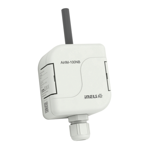
  9. Elko AirMD-100NB User manual

Elko AirMD-100NB User manual

+
+
SENS
1 / 4
AirMD-100
AirKey
5
02-104/2017 Rev.: 0
2
7
1
3
2
105°
12°
0 2 4 6 8 10 12 m
max.
2.2 m
4
ON
1 2 3
AirKey
AirMD-100
6
9
8
10
AirKey
1
2
3
9
9
ELKO EP, s.r.o.
Palackého 493
769 01 Holešov, Všetuly
Czech Republic
Tel.: +420 573 514 211
e-mail: [email protected]
www.elkoep.com
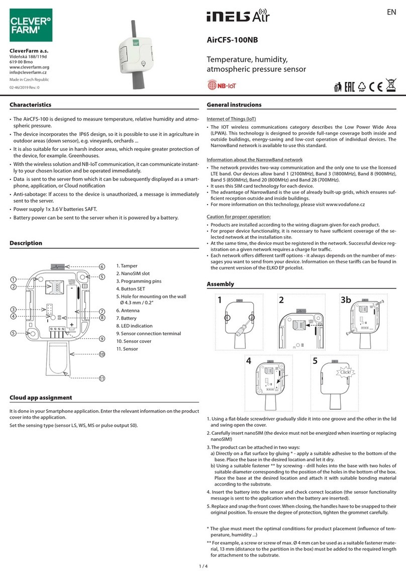
Characteristics
Description
EN
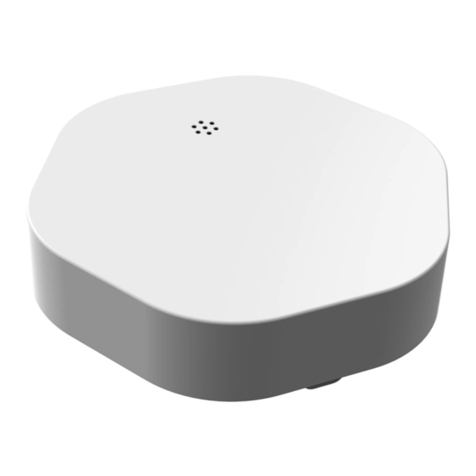
Motion detector
Key chain iNELS Air
AirMD-100
• The PIR motion detector is used to detect people moving in the interior.
• PIR sensitivity settings to eliminate unwanted switching.
• The detector oers a quick and comfortable solution for detecting motion in an
object. It’s just a simple installation at the location.
• The Sigfox, LoRa or NB-IoT network can be used for message transmission.
• Anti-sabotage function (tamper): When unauthorized interference with the detec-
tor occurs (disassembly) it sends an information message to the server.
• Data is sent to the server from which it can be subsequently displayed as a smart-
phone, application, or Cloud notication.
• Battery status information is sent as a message to the server.
• Power supply: battery 2x 1.5 V AA.
• The Disarm is done either with a message from the server or by using the AirKey
key fob that communicates with the detector wirelessly.
AirKey
• It is used to activate and deactivate the motion detector when you enter or leave
the monitored area.
• One detector can be matched up to 32 key fobs. The key fob can be paired with any
number of detectors.
• Designed in black and white with laser printing.
• Battery power supply (3V/CR2032 - included in the supply) with battery life of
around 5 years based on frequency of use.
Detection field
1. Antenna
2. Battery
3. Blue LED
4. DIP Switch
- DIP1: no function
- DIP2: no function
- DIP3: programming / deleting the
detector memory
5. Tamper
6. Motion sensor
7. Setting SENS component- sensitivity
adjustment of the PIR sensor
Top view Side view
The detection area is covered by three cones
8. Transmitter indication
9. Control button
10. Control button DISARM
Internet of Things (IoT)
• The IOT wireless communications category describes the Low Power Wide Area
(LPWA). This technology is designed to provide full-range coverage both inside and
outside buildings, energy-saving and low-cost operation of individual devices. Indivi-
dual networks - Sigfox, LoRa, NarrowBand - are available to use this standard.
Sigfox network information
• The network supports bidirectional communication but with a limited number of feed-
backs. It uses the free frequency band divided by Radio Frequency Zones (RCZ).
• RCZ1 (868 MHz) Europe, Oman, South Africa
• RCZ2 (902 MHz) North America
• RCZ3 (923 MHz) Japan
• RCZ4 (920 MHz) South America, Australia, New Zealand, Singapore, Taiwan
• Sigfox has more coverage across countries, so it is better suited for long distance mo-
nitoring.
• For more information on this technology, please visit www.sigfox.com.
LoRa network information
• The network is bidirectional and its communication uses free frequency band.
• 865 - 867 MHz India
• 867 - 869 MHz Europe
• 902 - 928 MHz North America, Japan, Korea
• The advantage of this network is the possibility of freely deploying individual stations
in local locations, thus strengthening their signal. It can therefore be used eciently in
company premises or, for example, in local parts of cities.
• For more information on this technology, please visit www.lora-alliance.org.
Information about the NarrowBand network
• The network provides two-way communication and the only one to use the licensed
LTE band. Our devices allow band 1 (2100MHz), Band 3 (1800MHz), Band 8 (900MHz),
Band 5 (850MHz), Band 20 (800MHz) and Band 28 (700MHz).
• It uses this SIM card technology for each device.
• The advantage of NarrowBand is the use of already built-up grids, which ensures su-
cient reception outside and inside buildings.
• For more information on this technology, please visit www.vodafone.cz
Caution for proper operation:
• Products are installed according to the wiring diagram given for each product.
• For proper device functionality, it is necessary to have sucient coverage of the selec-
ted network at the installation site.
• At the same time, the device must be registered in the network. Successful device re-
gistration on a given network requires a charge for trac.
• Each network oers dierent tari options - it always depends on the number of me-
ssages you want to send from your device. Information on these taris can be found in
the current version of the ELKO EP pricelist.
Cloud app assignment
It is done in your Smartphone application. Enter the relevant information on the product
cover into the application.
General instrucions
Made in Czech Republic
1
ON
1 2 3
+
+
+
-
+
-
Click!
9
ON
1 2 3
+
+
7
Click!
6a) b) c)
RF
Base Transceiver
Station
AirKey AirMD-100
AirKey
1
2
3
4
ON
1 2 3
+
+
5a) b)
ON
1 2 3
+
+
2a) AirMD-100NB 2b) AirMD-100NB
ON
1 2 3
+
+
8
+
-
+
-
Assembly AirMD-100
Recommendations for installation
• When installing the detector, consider the handling area above the detector (to replace
the batteries, etc.). Do not exceed the maximum recommended height for placement.
• The detector is intended for indoor use.
• After inserting the battery, the time delay is 15 seconds to stabilize the PIR detector, and
then the motion detection function is activated.
* The glue must meet the optimal conditions for product placement (inuence of tem-
perature, humidity ...)
** For example, a countersunk head screw can be used as a suitable fastener, screw of
max. Ø 3 mm.
When handling a device unboxed it is important to avoid contact with
liquids. avoid unnecessary contact with the components of the device. Do
not touch the metal objects inside the unit.
Safe handling
Function
If no movement is detected by the motion detector for 15 minutes, the guard will be
activated automatically.
Data status report sent at a max of four-hour intervals (You can edit the message from
the server).
Disarm (DISARM)
When capturing motion in the guard state, the blue LED lights up and an uninterrupted
beep sounds at the same time. Press the button on the AirKey Controller. The audible
alarm is switched o and the transition to the DISARM status is conrmed by a short
beep.
If the guard is not switched o within 5 seconds, the audible alarm turns o and the
detector sends the alarm to the user.
If the detector is deactivated by the AirKey controller, it does not transmit the motion
detection information to the user.
1. Push the screwdriver into the opening at the top of the detector and open the device
cover.
2. Only with AirMD-100NB: Push the beaks (mouldings) on the setting component down
and remove the component from the base. Carefully insert nanoSIM (the device must
not be energized when inserting or replacing nanoSIM!)
3. You can attach the product either by sticking * on a at surface - apply a suitable adhe-
sive to the outside of the base. Place the base in the desired location and let it dry.
4. Or using a suitable fastener ** by screwing. Push the beaks (mouldings) on the setting
component down and remove the component from the base.
5. Depending on the required location, remove the screw plugs from the base (e.g. with
a screwdriver).
a) To place on a at surface.
b) To place in a corner.
6. Place the base at the desired location and attach it with suitable bonding material accor-
ding to the substrate**.
a) On a at surface.
b), c) into a corner.
7. Insert the component into the base and snap into place with pressure, gently.
8. Program the instrument (see chapter Programming the controller) and adjust the sen-
sitivity of the PIR sensor.
9. Replace and snap the front cover.
3 / 4
1
ON
1 2 3
+
+
ON
1 2 3
2
ON
1 2 3
+
+
4
ON
1 2 3
+
+
+
-
+
-
ON
1 2 3
6
ON
1 2 3
+
+
+
-
+
-
ON
1 2 3
ON
1 2 3
3
ON
1 2 3
+
+
+
-
+
-
4
ON
1 2 3
+
+
+
-
+
-
ON
1 2 3
6
ON
1 2 3
+
+
+
-
+
-
ON
1 2 3
ON
1 2 3
1
ON
1 2 3
+
+
ON
1 2 3
+
-
+
-
a
b
c2
ON
1 2 3
+
+
+
-
+
-
1 x / 1 s
3
ON
1 2 3
+
+
+
-
+
-
4 x / 1 s
5
ON
1 2 3
+
+
+
-
+
-
ON
1 2 3
ON
1 2 3
1
ON
1 2 3
+
+
ON
1 2 3
+
-
+
-
a
b
c2
ON
1 2 3
+
+
+
-
+
-
1 x / 1 s
3
ON
1 2 3
+
+
+
-
+
-
4 x / 1 s
4
ON
1 2 3
+
+
+
-
+
-
1 x / 1 s
1 2
ON
1 2 3
+
+
+
-
+
-
3
ON
1 2 3
+
+
+
-
+
-
Click!
3
+
CR2032
2 41
5
ON
1 2 3
+
+
+
-
+
-


5
ON
1 2 3
+
+
+
-
+
-


AirMD-100 |
AirKey |
Programming the controller for the detector
1. Switch DIP3 switch to ON.
2. Press the TAMPER button several times (to discharge the capacitors in the device).
3. Insert the batteries (observe the polarity). The blue LED flashes once every second, the
detector enters the programming mode.
4. Switch the DIP3 switch to OFF - this will lock the detector in the programming mode.
5. Press one of the control button DISARM ( ) on the controller, the LED on the detector
indicates blue LEDs with a long flash. This way you can program the desired number
of controllers.
6. To quit the programming mode, turn the DIP3 switch to ON and then back to OFF.
The blue LED on the detector will flash a long time. The detector will restart and go
into operating mode. After approx. 15 seconds (required to stabilize the PIR sensor), it
detects movement.
Deleting one controller from the detector
1. Remove one of the batteries (a). Turn the DIP3 switch to ON (b). Press the TAMPER
button (c) several times.
2. Return the battery. The blue LED flashes once every second, the detector enters the
programming mode.
3. Wait for the detector to enter the set up mode, which is indicated by blinking blue LED
at 4x per second.
4. Switch the DIP3 switch to OFF - this will lock the detector in the set up mode.
5. Press one of the control button DISARM ( ) on the controller, the LED on the detector
indicates blue LEDs with a long flash. The controller is erased from the detector me-
mory.
6. To exit the set up mode, turn the DIP3 switch to the ON position and then back to the
OFF position. The blue LED on the detector will flash a long time. The detector will
restart and go into operating mode. After approx. 15 seconds (required to stabilize the
PIR sensor), it detects movement.
Deleting all the controllers from the detector
1. Remove one of the batteries (a). Turn the DIP3 switch to ON (b). Press the TAMPER
button (c) several times.
2. Return the battery. The blue LED flashes once every second, the detector enters the
programming mode.
3. Wait for the detector to enter the set up mode, which is indicated by blinking blue LED
at 4x per second.
4. Wait until the detector returns to the programming mode, the blue LED blinks once
every second. This will erase all the controllers from the detector memory.
5. Next, you can start programming or return to the programming mode (see chapter
Programming the controller).
Replacing batteries
1. Push the screwdriver into the opening at the top of the detector and open the device
cover.
2. Remove the original battery and insert new batteries into the battery holder. Beware
of polarity. The blue LED on the detector will blink.
3. Replace and snap the front cover.
Insertion and replacement of a battery
1. Using a Phillips head screwdriver, remove the screw on the back of the transmitter.
Remove the rear cover.
2. Carefully remove the device from the box.
3. Slide the CR2032 battery into the battery holder. Observe the polarity.
4. Insert the device into the housing so that it clicks onto the tabs and to the stops inside
the housing.
5. Replace the rear cover and replace the screw.
AirMD-100S AirMD-100L AirMD-100NB
4 / 4
AirKey/W AirKey/B
Technical parameters
Power supply
Battery power:
Battery life by frequency *:
1x 10 minutes
1x 60 minutes
1x 12 hours
1x 24 hours
Setting
Alarm Detection:
Battery status view:
Indication
- blue LED:
Programming:
Detection angle:
Detection distance:
Recommended working height:
Communication
Protocol:
Transmitter frequency:
Range in open space:
Protocol:
Transmitter frequency:
Range in open space:
Transmission power (max.):
Other parameters
Working temperature:
Storage temperature:
Operating position:
Mounting:
Protection degree:
Color:
Dimension:
Weight:
battery 2x 1.5V AA
0.3 year 1.4 year 1.2 year
1.1 years 2 years 1.1 years
1.6 year 2 years 1.9 year
2 years 2 years 2 years
message to the server, audible alarm
only when the battery is powered by a message on the server
motion detected
DIP Switch 3
105°
max. 12 m
max. 2.2 m
iNELS RF Control
868 MHz
up to 100m
Sigfox LoRa NB-IoT
RCZ1 868 MHz 868 MHz LTE Cat NB1**
Approx. 50 km*** Approx. 10 km*** Approx. 30 km***
25 mW / 14 dBm 25 mW / 14 dBm 200 mW / 23 dBm
0…+50°C (Pay attention to the operating
temperature of batteries)
-30…+70°C
vertical
glue / screws
IP20
white
46 x 105 x 43 mm
62 g (without battery)
* Values are calculated without activating the alarm, which is energy intensive
** Multiple frequency bands of B1 / B3 / B5 / B8 / B20 / B28
*** Depending on network coverage
Warning
Read the operating instructions before installing the device and putting it into opera-
tion. Instruction manual is designated for mounting and also for user of the device. It is
always a part of its packing. Installation and connection can be carried out only by a per-
son with adequate professional qualication upon understanding this instruction man-
ual and functions of the device, and while observing all valid regulations. Trouble-free
function of the device also depends on transportation, storing and handling. In case you
notice any sign of damage, deformation, malfunction or missing part, do not install this
device and return it to its seller. It is necessary to treat this product and its parts as elec-
tronic waste after its lifetime is terminated. Before starting installation, make sure that all
wires, connected parts or terminals are de-energized. While mounting and servicing ob-
serve safety regulations, norms, directives and professional, and export regulations for
working with electrical devices. Do not touch parts of the device that are energized – life
threat. To ensure the transmission of the radio signal, make sure that the devices in the
building where the installation is installed are correctly located. Unless otherwise stated,
the devices are not intended for installation in outdoor and damp areas, they must not
be installed in metal switchboards or in plastic cabinets with metal doors - this prevents
transmission of the radio frequency signal. iNELS Air is not recommended for control-
ling life-saving instruments or for controlling hazardous devices such as pumps, heaters
without thermostat, lifts, hoists, etc. - radio frequency transmission may be overshad-
owed by obstruction, interference, transmitter battery may be discharged etc., thereby
disabling the remote control.
Supply voltage:
Transmission indication:
Number of buttons:
Communication
Protocol:
Transmitter frequency:
Range in open space:
Signal transmission method:
Other parameters
Operating temperature:
Operating position:
Color:
Protection:
Contamination degree:
Dimensions:
Weight:
3 V battery CR 2032
red LED
4
iNELS RF Control RFIO
868 MHz
up to 100 m
unidirectionally addressed message
-10 ... +50 °C
any
white black
IP20
2
64 x 25 x 10 mm
10 g (without battery)
Notice:
Only use batteries designed for this product correctly inserted in the device! Immediately replace
weak batteries with new ones. Do not use new and used batteries together. If necessary, clean the
battery and contacts prior to using. Avoid the shorting of batteries! Do not dismantle batteries, do
not charge them and protect them from extreme heating - danger of leakage! Upon contact with acid,
immediately rinse the aected area with a stream of water and seek medical attention. Keep batteries
out of the reach of children. Batteries must be recycled or returned to an appropriate location (e.g.
collection container) in accordance with local legal provisions.

Other manuals for AirMD-100NB

1

This manual suits for next models

8

Other Elko Accessories manuals

Elko iNels RFDSC-71N User manual

Elko

Elko iNels RFDSC-71N User manual

Elko SmartSensor Leakage Wireless User manual

Elko

Elko SmartSensor Leakage Wireless User manual

Elko Inels RFDSC-11 User manual

Elko

Elko Inels RFDSC-11 User manual

Elko iNELS RFDSC-71 User manual

Elko

Elko iNELS RFDSC-71 User manual

Elko iNELS Air AirIM-100NB User manual

Elko

Elko iNELS Air AirIM-100NB User manual

Elko iNels RFSC-61N User manual

Elko

Elko iNels RFSC-61N User manual

Elko iNels RFDSC-71N User manual

Elko

Elko iNels RFDSC-71N User manual

Elko inelsAir AirSOU-100NB User manual

Elko

Elko inelsAir AirSOU-100NB User manual

Elko Inels RFDSC-71 User manual

Elko

Elko Inels RFDSC-71 User manual

Elko iNels RFSC-11 User manual

Elko

Elko iNels RFSC-11 User manual

Elko inels RFDSC-71 User manual

Elko

Elko inels RFDSC-71 User manual

Elko iNELS Air AirCFS-100NB User manual

Elko

Elko iNELS Air AirCFS-100NB User manual

Elko Inels AirQS-101S User manual

Elko

Elko Inels AirQS-101S User manual

Elko iNels RFDSC-71N User manual

Elko

Elko iNels RFDSC-71N User manual

Elko RFWB-20/G User manual

Elko

Elko RFWB-20/G User manual

Elko Inels Air AirQS-101NB User manual

Elko

Elko Inels Air AirQS-101NB User manual

Elko SmartDim Puck Uni User manual

Elko

Elko SmartDim Puck Uni User manual

Elko iNELS RFDSC-71 User manual

Elko

Elko iNELS RFDSC-71 User manual

Elko SmartSensor User manual

Elko

Elko SmartSensor User manual

Elko INELS Air Series User manual

Elko

Elko INELS Air Series User manual

Elko Inels RFSC-11 User manual

Elko

Elko Inels RFSC-11 User manual

Elko Inels Air AirQS-100NB User manual

Elko

Elko Inels Air AirQS-100NB User manual

Elko DCL User manual

Elko

Elko DCL User manual

Elko inels RFDSC-11 User manual

Elko

Elko inels RFDSC-11 User manual

Popular Accessories manuals by other brands

fontastic FontaHome quick guide

fontastic

fontastic FontaHome quick guide

Honeywell DC311 FB Series quick start guide

Honeywell

Honeywell DC311 FB Series quick start guide

LifeShield SDC1001 manual

LifeShield

LifeShield SDC1001 manual

OLEI LR-1F Series user manual

OLEI

OLEI LR-1F Series user manual

Sport-thieme 113 6526 Assembly instruction

Sport-thieme

Sport-thieme 113 6526 Assembly instruction

AirTest TR-5200 Operation & maintenance manual

AirTest

AirTest TR-5200 Operation & maintenance manual

Thermo Scientific invitrogen EVOS OSI-2 user guide

Thermo Scientific

Thermo Scientific invitrogen EVOS OSI-2 user guide

Peavey 4000F Specifications

Peavey

Peavey 4000F Specifications

Hytronik HMW31 manual

Hytronik

Hytronik HMW31 manual

Showlite LF-5 user manual

Showlite

Showlite LF-5 user manual

Tobii Pro Chin Rest user manual

Tobii Pro

Tobii Pro Chin Rest user manual

Banner Q4X Series instruction manual

Banner

Banner Q4X Series instruction manual

Titan 110 Installation, maintenance & parts manual

Titan

Titan 110 Installation, maintenance & parts manual

Monoprice 13086 user manual

Monoprice

Monoprice 13086 user manual

Dräger Medical 8000 SC Periodic Maintenance Procedure

Dräger Medical

Dräger Medical 8000 SC Periodic Maintenance Procedure

LEGRAND 6 540 07 manual

LEGRAND

LEGRAND 6 540 07 manual

STAUFF OCS I quick start guide

STAUFF

STAUFF OCS I quick start guide

Panasonic EX-FC1 instruction manual

Panasonic

Panasonic EX-FC1 instruction manual

manuals.online logo
manuals.online logoBrands
  • About & Mission
  • Contact us
  • Privacy Policy
  • Terms and Conditions

Copyright 2025 Manuals.Online. All Rights Reserved.