manuals.online logo
Brands
  1. Home
  2. •
  3. Brands
  4. •
  5. Elko
  6. •
  7. Accessories
  8. •
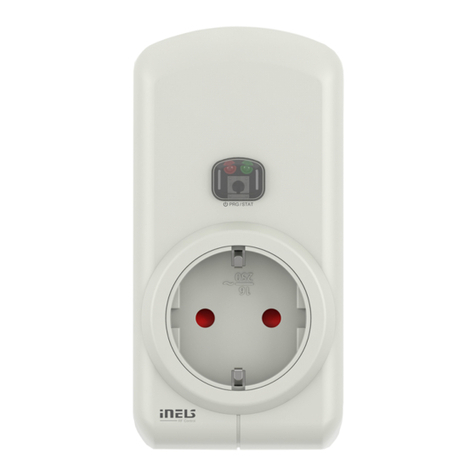
  9. Elko iNels RFSC-61N User manual

Elko iNels RFSC-61N User manual

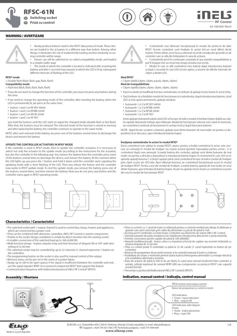
02-158/2021 Rev.0
RFSC-61N
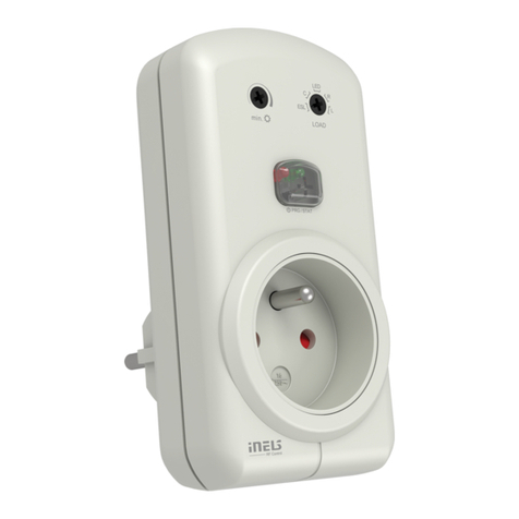
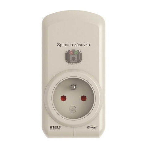
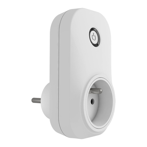
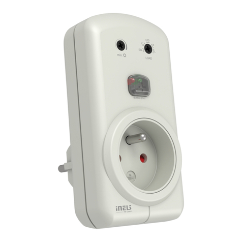
Switching socket
EN
Made in Czech Republic
Characteristics /
• The switched socket with 1 output channel is used to control fans, lamps, heaters and appliances,
which are connected by a power cord.
• They can be combined with detectors, controllers, iNELS RF Control or system components.
• Thanks to the socket design, installation is simple by direct insertion into the existing socket.
• It enables connection of the switched load up to 16A (4.000 W).
• Multi-function design - button, impulse relay and time function of delayed ON or OFF with time
setting of 2s-60 min.
• The switched socket may be controlled by up to 32 channels (1 channel represents 1 button on
the controller).
• The programming button on the socket is also used for manual control of the output.
• Memory status can be pre-set in the event of a power failure.
• Range up to 200 m (in open space), if the signal is insufficient between the controller and unit,
use the signal repeater RFRP-20 or protocol component RFIO2that support this feature.
• Communication frequency with bidirectional protocol iNELS RF Control2(RFIO2).
Assembly / Indication, manual control /
1/6
PROG button and output control
LED indication
• Green - input indication
• Red - output ON
WARNING /
• Newly produced drivers work in the RFIO2data protocol mode. These driv-
ers are loaded in the actuators in a different way than before. Among other
things, it eliminates the risk of inadvertently loading another randomly occur-
ring controller within range.
• Drivers can still be switched to so-called compatibility mode, and loaded
in a simpler (older way)
• The mode in which the controller is located is indicated after inserting the
battery and after 5 seconds have passed, at which the LED is lit by subsequent
different intervals of flashing of the LED.
RFIO2mode
= Double flash (flash, flash, gap, flash, flash)
Compatibility mode
= Flash fast (flash, flash, flash, flash, flash)
• If you do not want to change the function of the controller, you must not press any buttons during
this time.
• If we need to change the operating mode of the controller, after inserting the battery, when the
LED is permanently lit, we press at the same time:
• button 1 and 3 on RF KEY-40/60
• button 1 and 2 on RFWB-20/40
• button 1 and 2 on RFGB-20/40
• button 1 and 2 on RF KEY
you hold the buttons until the LED starts to signal the changed mode (double flash or fast flash).
After that, the buttons must be released. The selected mode of the function is stored in memory
and after replacing the battery, the controller continues to operate in the same mode.
NOTE: after each removal of the battery, we press one of the buttons several times to discharge the
device and reinsert the battery
UPDATE THE CONTROLLER ACTUATORS IN RFIO2MODE
If the controller is used in RFIO2mode, then to update the controller actuators, it is necessary to
switch not only the actuator to the update mode (according to the instructions for the actuator),
but also the controller in the following way: You remove the battery from the controller, press some
of the buttons several times to discharge the device, and reinsert the battery. At the moment when
the LED lights up, you press the 1 button and hold it down until the controller starts signaling the
updating mode with a short flashing of the LED. Then you release the button and the controller
now works in RFIO2update mode. To end the update mode, you remove the battery, press one of
the buttons several times, and then reinsert the battery. Now you do not press any button and the
controller starts again in RFIO2operating mode,
!
!
11 111 11
22 22
33 2
Enchufe conmutable
ES
ELKO EP, s.r.o. | Palackého 493 | 769 01 Holešov, Všetuly | Czech Republic | e-mail: [email protected] | Support: +420 778 427 366
ELKO EP ESPAÑA, S.L. | C/ Josep Martinez 15a, bj | 07007 Palma de Mallorca | e-mail: [email protected] | Tel.: +34 971 751 425 | Fax: +34 971 428 076
www.elkoep.com / www.elkoep.es
Indicación, control manual
Característica
• Enchufe conmutable con 1 canal de salida se utiliza para controlar los ventiladores, lámparas,
calentadores y aparatos que se conectan con su cable de alimentación.
• Se puede combinar con Detectores, Controladores o Unidades del sistema iNELS RF Control.
• Gracias a su diseño enchufe, la instalación es fácil y directa de conectarlo a un enchufe ya existente.
• Permite la conexión de cargas de hasta 16A (4000W).
• Versión multifunción - botón, relé de impulso y retardo de tiempo a la conexión o desconexión
con tiempo ajustable de 2s-60 min.
• Enchufe conmutable se puede controlar con hasta 32 canales (1 canal presenta un botón en el
controlador).
• Botón de programación en la unidad también sirve como control manual de salida.
• Posibilidad de ajustar el estado de la memoria en corte de energía.
• Alcance de hasta 200 mts (al aire libre), en caso de señal insuficiente entre controlador y la unidad se
puede utilizar el repetidor RFRP-20 o unidades con protocolo RFIO2, las cuales tienen esta función.
• Frecuencia de comunicación con protocolo bidireccional iNELS RF Control2(RFIO2).
• Se fabrica en 5 versiones del enchufe.
Montaje
botón PROG
LED Indicación
• Verde - indicador de alimentación
• Rojo - salida ON
• Los mandos de fabricación reciente trabajan en el modo de protocolo de datos
RFIO2 . Estos mandos se sincronizan con los actores de manera diferente a la que
se utilizaba hasta ahora. Con ello se eliminó, entre otras cosas, el riesgo de la sin-
cronización indeseada de otro mando que se encuentre de forma fortuita al alcance.
• Sigue existiendo la posibilidad de cambiar los mandos al modo de la llamada
compatibilidad y sincronizarlos de manera más sencilla (manera más antigua)
• El modo en el cual se encuentra el mando se indica tras introducir la pila y una
vez transcurridos los 5 segundos durante los cuales el diodo led está encendido re-
alizando el parpadeo con los siguientes intervalos diferentes.
Modo RFIO2
= Doble parpadeo (parpadeo, parpadeo, pausa, parpadeo, parpadeo)
Modo de Compatibilidad
= Parpadeo rápido (parpadeo, parpadeo, parpadeo, parpadeo)
• En el caso de que no queremos cambiar la función del mando, no debemos pulsar ningún botón durante
este tiempo.
• En el caso de que necesitamos cambiar el modo de operación del mando, tras insertar la pila, cuando el
LED está encendido permanentemente, pulsamos a la vez:
• el botón 1 y 3 en RF KEY-40/60
• botón 1 y 2 en RFWB-20/40
• botón 1 y 2 en RFGB-20/40
• botón 1 y 2 en RF KEY
aguantamos los botones hasta que el LED no empiece a señalizan el cambio del modo (doble parpadeo o
parpadeo rápido). Después hay que soltar los botones. El modo elegido de la función se guarda en la memo-
ria y tras cambiar la pila el mando sigue trabajando en el mismo modo.
NOTA: tras cada extracción de la pila pulsamos varias veces alguno de los botones para que el aparato se
descargue y volvemos a introducir la pila
SINCRONIZACIÓN DE LOS MANDOS CON LOS ACTORES EN EL MODO RFIO2
En el caso de que el mando se utilice en el modo RFIO2será necesario cambiar al modo de sincronización
no solo al actor (según el manual para el actor), sino también al mando, para poder sincronizar los mandos
con los actores, realizando los siguientes pasos: Extraemos la pila del mando, pulsamos varias veces alguno
de los botones para que el aparato se descargue y volvemos a introducir la pila. En el momento cuando se
enciende el LED pulsamos el botón 1 y lo mantenemos pulsado hasta que el mando no empiece a señalizar
el modo de sincronización mediante un parpadeo breve del LED. Luego soltamos el botón y el mando ahora
trabaja en el modo de sincronización RFIO2. Tras finalizar el modo de sincronización extraemos la pila, pul-
samos varias veces alguno de los botones y luego volvemos a introducir la pila. Ahora no pulsamos ningún
botón y el mando volverá a iniciarse en el modo RFIO2.
02-158/2021 Rev.0
RFSC-61N
Switching socket
EN
Made in Czech Republic
PROG > 1s
1 x PROG < 1s
1 x
Functions and programming with RF transmitters /
12 3
Select and press one button
on wireless switch, to this but-
ton will be assigned function
Button.
Press of programming button
on receiver RFSC-61N shorter
then 1 second will finish pro-
gramming mode. The LED
lights up according to the pre-
set memory function.
Press of programming but-
ton on receiver RFSC-61N for
1 second will activate receiver
RFSC-61N into programming
mode. LED is flashing in 1s
interval.
Programming /
Function button /
Description of button /

1 x

1 x
13
Two presses of your selected
button on the RF transmitter
assigns the function switch on
(must be a lapse of 1s between
individual presses).
Press of programming button
on receiver RFSC-61N shorter
then 1 second will finish pro-
gramming mode. The LED
lights up according to the pre-
set memory function.
Press of programming but-
ton on receiver RFSC-61N for
1 second will activate receiver
RFSC-61N into programming
mode. LED is flashing in 1s
interval.
Programming /
PROG > 1s
1 x PROG < 1s
1 x
Function switch on /
Description of switch on /

1 x
The output contact will be closed by pressing the button.
2

2 x
2/6
The output contact will be closed by pressing the button and opened by releasing
the button.
For the correct execution of individual commands (press = closing / releasing the
button = opening), the time delay between these commands must be a min of .
1s (press - delay 1s - release).




Compatibility /
The device can be combined with all system components, controls and devices of iNELS RF
Control and iNELS RF Control2.
The detector can be assigned an iNELS RF Control2(RFIO2) communication protocol.
Radio frequency signal penetration through various construction materials /





RFRP-20N
60 - 90 % 80 - 95 % 20 - 60 % 0 - 10 % 80- 90 %
brick walls wooden structures
with plaster boards
reinforced
concrete metal partitions common glass
Enchufe conmutable
ES
ELKO EP, s.r.o. | Palackého 493 | 769 01 Holešov, Všetuly | Czech Republic | e-mail: [email protected] | Support: +420 778 427 366
ELKO EP ESPAÑA, S.L. | C/ Josep Martinez 15a, bj | 07007 Palma de Mallorca | e-mail: [email protected] | Tel.: +34 971 751 425 | Fax: +34 971 428 076
www.elkoep.com / www.elkoep.es
Funciones y programación con RF controlador
Función botón
Descripción de función botón
Programación
Pulsando el botón de progra-
mación del enchufe RFSC-61N
durante más de 1 segundo,
entra al modo de la progra-
mación. LED parpadea en in-
tervalo de 1 segundo.
Pulsación al botón seleccionado
del RF controlador se asigna la
función botón. Pulsando el botón de progra-
mación del enchufe RFSC-61N
durante menos de 1 segundo,
terminará el modo de pro-
gramación. LED se ilumina
según la función de memoria
ajustada.
Programación
Pulsando el botón de progra-
mación del enchufe RFSC-61N
durante más de 1 segundo,
entra al modo de la progra-
mación. LED parpadea en in-
tervalo de 1 segundo.
2x pulsaciones al botón selec-
cionado del RF controlador asig-
na la función encender, entre los
pulsos hay que cumplir retardo
de 1s.
Pulsando el botón de progra-
mación del enchufe RFSC-61N
durante menos de 1 segundo,
terminará el modo de pro-
gramación. LED se ilumina
según la función de memoria
ajustada.
Función encender
Descripción de función encender
Pulsando el botón del pulsador el contacto de salida se activa.
Pulsando un botón del pulsador el contacto de salida se activa, al soltar el botón
la salida se desactiva.
Para la correcta ejecución de las órdenes (pulso = conexión / suelto del botón =
desconexión), el tiempo de demora entre estas órdenes debe ser min. 1s (pulso
- demora 1s - suelto).
Compatibilidad
El elemento se puede combinar con todos las unidades del sistema, controlado-
res y unidades del sistema iNELS RF Control y iNELS RF Control2.
A la unidad tambien se pueden agregar los detectores denominados con protó-
colo iNELS RF Control2(RFIO2).
pared de ladrillo
estructuras de
madera con placas
de yeso
hormigón armado chapas
metálicas vidrio normal
Transmisión de señales de radiofrecuencia en varios materiales de la construcción
02-158/2021 Rev.0
RFSC-61N
Switching socket
EN
Made in Czech Republic
Press of programming button
on receiver RFSC-61N shorter
then 1 second will finish pro-
gramming mode. The LED
lights up according to the pre-
set memory function.
1
3/6
3
Four presses of your selected
button on the RF transmitter as-
signs the function impulse relay
(must be a lapse of 1s between
individual presses).
Press of programming but-
ton on receiver RFSC-61N for
1 second will activate receiver
RFSC-61N into programming
mode. LED is flashing in 1s
interval.
Programming /
Function impulse relay /
Description of impulse relay /

1 x
PROG > 1s
1 x PROG < 1s
1 x
The output contact will be switched to the opposite position by each press of the
button. If the contact was closed, it will be opened and vice versa.
2

4 x
setting time delay 2s ... 60min. /
3
Assignment of the delayed off
function is performed by five
presses of the selected button
on the RF transmitter (must be
a lapse of 1s between individual
presses).
Press of programming button
longer then 5 seconds, will
activate actuator into timing
mode. LED flashs 2x in each
1s interval. Upon releasing the
button, the delayed return
time starts counting.
Press of programming but-
ton on receiver RFSC-61N for
1 second will activate receiver
RFSC-61N into programming
mode. Red LED is flashing in
1s interval.
Programming /
1
PROG > 1s
1 x PROG > 5s
1 x
Funcion delayed off /
Description of delayed o /

1 x
The output contact will be closed by pressing the button and opened after the set
time interval has elapsed.
2

5 x




3
Three presses of your selected
button on the RF transmitter
assigns the function switch off
(must be a lapse of 1s between
individual presses).
Press of programming button
on receiver RFSC-61N shorter
then 1 second will finish pro-
gramming mode. The LED
lights up according to the pre-
set memory function.
Press of programming but-
ton on receiver RFSC-61N for
1 second will activate receiver
RFSC-61N into programming
mode. LED is flashing in 1s
interval.
Programming /
Function switch off /
Description of switch o /

1 x
1
PROG > 1s
1 x PROG < 1s
1 x
The output contact will be opened by pressing the button.
2

3 x


Enchufe conmutable
ES
ELKO EP, s.r.o. | Palackého 493 | 769 01 Holešov, Všetuly | Czech Republic | e-mail: [email protected] | Support: +420 778 427 366
ELKO EP ESPAÑA, S.L. | C/ Josep Martinez 15a, bj | 07007 Palma de Mallorca | e-mail: [email protected] | Tel.: +34 971 751 425 | Fax: +34 971 428 076
www.elkoep.com / www.elkoep.es
Función relé de impulso-telerruptor
Descripción de función telerruptor
Con cada pulsación del botón el contacto de salida cambia la posición. Si estaba
cerrado - se abre, si estaba abierto - se cierra.
Programación
Pulsando el botón de progra-
mación del enchufe RFSC-61N
durante más de 1 segundo,
entra al modo de la progra-
mación. LED parpadea en in-
tervalo de 1 segundo.
4x pulsaciones al botón selec-
cionado del RF controlador
asigna la función telerruptor,
entre los pulsos hay que cumplir
retardo de 1s.
Pulsando el botón de progra-
mación del enchufe RFSC-61N
durante menos de 1 segundo,
terminará el modo de pro-
gramación. LED se ilumina
según la función de memoria
ajustada.
Programación
ajuste del tiempo retardo 2s ... 60min.
Pulsando el botón de progra-
mación del enchufe RFSC-61N
durante más de 1 segundo,
entra al modo de la progra-
mación. LED parpadea en in-
tervalo de 1 segundo.
5x pulsaciones al botón selec-
cionado del RF controlador
asigna la función retardo en OFF,
entre los pulsos hay que cumplir
retardo de 1s.
Pulsación al botón de progra-
mación a más de 5 segundos,
activará modo temporizador.
LED parpadea 2x en intervalos
de 1 segundo. Después de
soltar el botón comienza el
tiempo de retardo en OFF.
Función retardo a la desconexión
Descripción de función retardo en OFF
Pulsando un botón el contacto de salida se enciende y se apaga después de un
período de tiempo determinado.
Función apagar
Descripción de función apagar
Pulsando el botón del pulsador el contacto de salida se desactiva.
Programación
Pulsando el botón de progra-
mación del enchufe RFSC-61N
durante más de 1 segundo,
entra al modo de la progra-
mación. LED parpadea en in-
tervalo de 1 segundo.
3x pulsaciones al botón selec-
cionado del RF controlador
asigna la función apagar, entre
los pulsos hay que cumplir re-
tardo de 1s.
Pulsando el botón de progra-
mación del enchufe RFSC-61N
durante menos de 1 segundo,
terminará el modo de pro-
gramación. LED se ilumina
según la función de memoria
ajustada.
02-158/2021 Rev.0
RFSC-61N
Switching socket
EN
Made in Czech Republic
Pressing the PROG button for
longer than 8 seconds brings
the socket into the timing
mode. The LED will give a sin-
gle flash 3x and a double flash
3x, then goes out.
setting the number of hours of delay in hourly intervals - 1h ... 10h /
3
Assignment of the delayed off
function is performed by five
presses of the selected button
on the RF transmitter (must be
a lapse of 1s between individual
presses).
Press of programming but-
ton on receiver RFSC-61N for
1 second will activate receiver
RFSC-61N into programming
mode. Red LED is flashing in
1s interval.
1
PROG > 1s
1 x PROG > 8s
1 x
5Press of programming button
on receiver RFSC-61N shorter
then 1 second will finish pro-
gramming mode. The LED
lights up according to the pre-
set memory function.
By the number of presses of
the selected RF transmitter
button, set the required de-
lay (1 press - 1h, ... 10 presses
- 10h). Each press on the RF
transmitter is indicated by a
flash of the LED on the socket
RFSC-61N.
PROG < 1s
1 x
t = 1h. . .10h

Note: modes 2s - 60min and 1 hr up to 10 hr cannot be combined. /
4/6
2

5 x
4

X x
23
Assignment of the delayed on
function is performed by six
presses of the selected button
on the RF transmitter (must be
a lapse of 1s between individual
presses).
Press of programming button
longer then 5 seconds, will
activate actuator into timing
mode. LED flashs 2x in each
1s interval. Upon releasing the
button, the delayed return
time starts counting.
Press of programming but-
ton on receiver RFSC-61N for
1 second will activate receiver
RFSC-61N into programming
mode. LED is flashing in 1s
interval.
Programming /
PROG > 1s
1 x

6 x PROG > 5s
1 x
setting time delay 2s ... 60min. /
1
Function delayed on /
Description of delayed on /

1 x
The output contact will be opened by pressing the button and closed after the set
time interval has elapsed.





5Press of programming button
on receiver RFSC-61N shorter
then 1 second will finish pro-
gramming mode. The LED
lights up according to the pre-
set memory function.
After the desired time has
elapsed (range of 2s ... 60min),
the timing mode ends by
pressing the button on the
RF transmitter, to which the
delayed return function is
assigned. This stores the set
time interval into the actuator
memory.
t = 2s . . . 60min.
PROG < 1s
1 x

4

1 x

Enchufe conmutable
ES
ELKO EP, s.r.o. | Palackého 493 | 769 01 Holešov, Všetuly | Czech Republic | e-mail: [email protected] | Support: +420 778 427 366
ELKO EP ESPAÑA, S.L. | C/ Josep Martinez 15a, bj | 07007 Palma de Mallorca | e-mail: [email protected] | Tel.: +34 971 751 425 | Fax: +34 971 428 076
www.elkoep.com / www.elkoep.es
ajuste del tiempo retardo en intervalo por horas - 1h ... 10h
Pulsando el botón de progra-
mación del enchufe RFSC-61N
durante más de 1 segundo,
entra al modo de la progra-
mación. LED parpadea en in-
tervalo de 1 segundo.
5x pulsaciones al botón selec-
cionado del RF controlador
asigna la función retardo en OFF,
entre los pulsos hay que cumplir
retardo de 1s.
Con un largo pulso del botón
de programación del enm-
chufe durante 8 segundos en-
trara al modo de temporiza-
dor, LED parpadea tres veces,
luego se apaga de nuevo tres
veces y se apaga.
El número de pulsos al botón
seleccionado de controlador,
se ajuste el retardo deseado (1
pulso - 1h, ... 10 pulsos - 10h).
Cada pulso sobre el controla-
dor RF se indica mediante el
parpadeo del LED.
Pulsando el botón de progra-
mación del enchufe RFSC-61N
durante menos de 1 segundo,
terminará el modo de pro-
gramación. LED se ilumina
según la función de memoria
ajustada.
Nota: modos 2s - 60min y 1h - 10 h no es posible combinar.
Programación
ajuste del tiempo retardo 2s ... 60min.
Pulsando el botón de progra-
mación del enchufe RFSC-61N
durante más de 1 segundo,
entra al modo de la progra-
mación. LED parpadea en in-
tervalo de 1 segundo.
6x pulsaciones al botón selec-
cionado del RF controlador
asigna la función retardo en ON,
entre los pulsos hay que cumplir
retardo de 1s.
Pulsación al botón de progra-
mación a más de 5 segundos,
activará modo temporizador.
LED parpadea 2x en intervalos
de 1 segundo. Después de
soltar el botón comienza el
tiempo de retardo en ON.
Función retardo a la conexión
Descripción del retardo en ON
Pulsando un botón el contacto de salida se apaga y vuelve encenderse después
de un período de tiempo determinado.
Después del tiempo deseado
(a menos de 2s ... a 60min) el
modo de temporizador se ter-
mina pulsando el botón del
controlador RF, donde está
asignada la función retardo
en OFF. Tiempo establecido
se guarda en la memoria de
enchufe.
Pulsando el botón de progra-
mación del enchufe RFSC-61N
durante menos de 1 segundo,
terminará el modo de pro-
gramación. LED se ilumina
según la función de memoria
ajustada.
02-158/2021 Rev.0
RFSC-61N
Switching socket
EN
Made in Czech Republic
3Pressing the PROG button for
longer than 8 seconds brings
the socket into the timing
mode. The LED will give a sin-
gle flash 3x and a double flash
3x, then goes out.
PROG > 8s
1 x
Assignment of the delayed on
function is performed by six
presses of the selected button
on the RF transmitter (must be
a lapse of 1s between individual
presses).
Press of programming but-
ton on receiver RFSC-61N for
1 second will activate receiver
RFSC-61N into programming
mode. LED is flashing in 1s
interval.
PROG > 1s
1 x
5Press of programming button
on receiver RFSC-61N shorter
then 1 second will finish pro-
gramming mode. The LED
lights up according to the pre-
set memory function.
By the number of presses of
the selected RF transmitter
button, set the required de-
lay (1 press - 1h, ... 10 presses
- 10h). Each press on the RF
transmitter is indicated by a
flash of the LED on the socket
RFSC-61N.
PROG < 1s
1 x
setting the number of hours of delay in hourly intervals - 1h ... 10h /
t = 1h. . .10h

5/6
Note: modes 2s - 60min and 1 hr up to 10 hr cannot be combined. /
12

6 x

X x
4
Deleting one position of the transmitter /
Deleting the socket /
Deleting the entire memory /
By pressing the programming button on the actuator for 5 sec-
onds, deletion of one transmitter activates. LED flashs 4x in each
1s interval.
Pressing the required button on the transmitter deletes it from
the actuator's memory.
To confirm deletion, the LED will confirm with a flash long and the
component returns to the operating mode. The memory status
is not indicated.
Deletion does not affect the pre-set memory function.
By pressing the programming button on the actuator for 8 sec-
onds, deletion occurs of the actuator's entire memory. LED flashs
4x in each 1s interval.
The actuator goes into the programming mode, the LED flashes
in 0.5s intervals (max. 4 min.).
You can return to the operating mode by pressing the Prog but-
ton for less than 1s. The LED lights up according to the pre-set
memory function and the component returns to the operating
mode. Deletion does not affect the pre-set memory function.
PROG > 5s
1 x PROG > 8s
1 x
Programming with RF control units /
The address listed on the rear of the socket is used for programming and
controlling sockets RFSC-61N by RF control units.





5Press of programming button
on receiver RFSC-61N shorter
then 1 second will finish pro-
gramming mode. The LED
lights up according to the pre-
set memory function.
After the desired time has
elapsed (range of 2s ... 60min),
the timing mode ends by
pressing the button on the RF
transmitter, to which the de-
layed on function is assigned.
This stores the set time inter-
val into the actuator memory.
PROG < 1s
1 x
t = 2s . . . 60min.


1 x
4

Enchufe conmutable
ES
ELKO EP, s.r.o. | Palackého 493 | 769 01 Holešov, Všetuly | Czech Republic | e-mail: [email protected] | Support: +420 778 427 366
ELKO EP ESPAÑA, S.L. | C/ Josep Martinez 15a, bj | 07007 Palma de Mallorca | e-mail: [email protected] | Tel.: +34 971 751 425 | Fax: +34 971 428 076
www.elkoep.com / www.elkoep.es
ajuste del tiempo retardo en intervalo por horas - 1h ... 10h
Pulsando el botón de progra-
mación del enchufe RFSC-61N
durante más de 1 segundo,
entra al modo de la progra-
mación. LED parpadea en in-
tervalo de 1 segundo.
6x pulsaciones al botón selec-
cionado del RF controlador
asigna la función retardo en ON,
entre los pulsos hay que cumplir
retardo de 1s.
Con un largo pulso del botón
de programación del enm-
chufe durante 8 segundos en-
trara al modo de temporiza-
dor, LED parpadea tres veces,
luego se apaga de nuevo tres
veces y se apaga.
El número de pulsos al botón
seleccionado de controlador,
se ajuste el retardo deseado
(1 pulso - 1h, ... 10 pulsos - 10h).
Cada pulso sobre el controla-
dor RF se indica mediante el
parpadeo del LED.
Pulsando el botón de progra-
mación del enchufe RFSC-61N
durante menos de 1 segundo,
terminará el modo de pro-
gramación. LED se ilumina
según la función de memoria
ajustada.
Nota: modos 2s - 60min y 1h - 10 h no es posible combinar.
Borrar enchufe
Borrar una posición del controlador
Con un largo pulso al botón de programación del enchufe RF
por un período de 5 segundos se activará modo "borrar" un solo
transmisor. LED 4x parpadeará en intervalo de un segundo.
Al pulsar el botón del controlador se elimina de memoria de la
unidad.
Para confirmar la eliminación, el LED parpadeará durante un mo-
mento largo y la unidad volverá al modo de funcionamiento. El
estado de la memoria no está indicado.
Borrar no afecta a la función de memoria ajustada.
Borrar toda memoria
Con un largo pulso del botón de programación del enchufe du-
rante 8 segundos se borrará toda memoria de la unidad. LED 4x
parpadeará en intervalo de un segundo.
Unidad entra al modo de programación, el LED parpadea en in-
tervalos de 0.5s (máx. 4 min.).
Para volver al modo operativo, pulse el botón Prog por menos de
1 segundo. LED se enciende de acuerdo con la función de me-
moria de ajuste y la unidad vuelve al modo de funcionamiento.
Borrar no afecta a la función de memoria ajustada.
Programación con Unidades del sistema RF
Para la programación y control de enchufes RFSC-61N mediante Unidades
de sistema RF sirve la dirección indicada en la parte trasera del enchufe.
Después del tiempo deseado
(a menos de 2s ... a 60min) el
modo de temporizador se ter-
mina pulsando el botón del
controlador RF, donde está
asignada la función retardo
en ON. Tiempo establecido
se guarda en la memoria de
enchufe.
Pulsando el botón de progra-
mación del enchufe RFSC-61N
durante menos de 1 segundo,
terminará el modo de pro-
gramación. LED se ilumina
según la función de memoria
ajustada.
Technical parameters /
Supply voltage:
Supply voltage frequency:
Apparent power:
Dissipated power:
Supply voltage tolerance:
Output
Number of contacts:
Rated current:
Switching power:
Peak current:
Switching voltage:
Min. switching power DC:
Mechanical service life:
Electrical service life (AC1):
Control
Wirelessly:
Communication protocol:
Frequency:
Function repeater:
Manual control:
Range:
Other data
Operating temperature:
Working position:
Mounting:
Protection:
Overvoltage category:
Contamination degree:
Dimensions:
Weight:
Related standards:
Attention:
When you instal iNELS RF Control system, you have to keep minimal
distance 1 cm between each units.
Between the individual commands must be an interval of at least 1s.
Instruction manual is designated for mounting and also for user of the device. It is always a part of its packing. Instal-
lation and connection can be carried out only by a person with adequate professional qualification upon under-
standing this instruction manual and functions of the device, and while observing all valid regulations. Trouble-free
function of the device also depends on transportation, storing and handling. In case you notice any sign of damage,
deformation, malfunction or missing part, do not install this device and return it to its seller. It is necessary to treat
this product and its parts as electronic waste after its lifetime is terminated. Before starting installation, make sure
that all wires, connected parts or terminals are de-energized. While mounting and servicing observe safety regula-
tions, norms, directives and professional, and export regulations for working with electrical devices. Do not touch
parts of the device that are energized – life threat. Due to transmissivity of RF signal, observe correct location of
RF components in a building where the installation is taking place. RF Control is designated only for mounting in
interiors. Devices are not designated for installation into exteriors and humid spaces. The must not be installed into
metal switchboards and into plastic switchboards with metal door – transmissivity of RF signal is then impossible.
RF Control is not recommended for pulleys etc. – radiofrequency signal can be shielded by an obstruction, inter-
fered, battery of the transceiver can get flat etc. and thus disable remote control.
Warning
6/6
• Memory function on:
- For functions 1-4, these are used to store the last state of the relay output before the supply
voltage drops, the change of state of the output to the memory is recorded 15 seconds after
the change.
- For functions 5-6, the target state of the relay is immediately entered into the memory after the
delay, after re-connecting the power, the relay is set to the target state.
• Memory function off:
When the power supply is reconnected, the relay remains off.
Selecting the memory function /
12
Press of programming button on receiver RFSC-61N for 1 second
will activate receiver RFSC-61N into programming mode. LED is
flashing in 1s interval.
Pressing the programming button on the RFSC-61N receiver for
less than 1 second will finish the programming mode, this will
reverse the memory function. The LED lights up according to the
current pre-set memory function. The set memory function is
saved. Every other change is made in the same way.
PROG > 1s
1 x PROG < 1s
1 x


Especificaciones técnicas
Tensión de alimentacion:
Frecuencia de la tensión de alimentación:
Consumo aparente:
Consumo de perdida:
Tolerancia de alimentación:
Salida
Número de contactos:
Corriente nominal:
Potencia de conmutación:
Pico de corriente:
Tensión de conmutación:
Conmutación de potencia min.DC:
Vida mecánica:
Vida eléctrica (AC1):
Control
Inalámbrico:
Protocolo de comunicación:
Frecuencia:
Función repeater:
Control manual:
Rango al aire libre:
Más información
Temperatura de funcionamiento:
Posición de funcionamiento:
Montaje:
Protección:
Categoría de sobretensión:
Grado de contaminación:
Dimensiones:
Peso:
Normas conexas:
Advertencia:
En la instalación de iNELS RF Control debe haber una distancia mínima
entre las diferentes unidades de un centímetro.
Entre los diferentes ordenes debe pasar al menos 1s.
El manual de uso está dirigido para la instalación y el usuario del dispositivo. Manual siempre está incluido en
embalaje. La instalación y conexión puede realizar sólo personal con adecuadas cualificaciones profesionales, de
conformidad con todas las regulaciones aplicadas, y que está perfectamente familiarizado con estas instrucciones
y funciones del dispositivo. Función del dispositivo también depende del transporte, almacenamiento y la manipu-
lación. Si se observa cualquier signo de daño, deformación, mal funcionamiento o pieza que falta, no instale este
producto y devolvelo al vendedor. Con el producto y sus componentes debe ser tratado después de su vida útil
como con residuos electrónicos. Antes de iniciar la instalación, asegúrese de que todos los cables, partes o termi-
nales conectados están sin la conexión a la red. En el montaje y el mantenimiento se deben observar las normas de
seguridad, normas, directivas y reglamentos para trabajar con equipos eléctricos. No toque las partes del dispositivo
que están conectadas en la red - puede producir peligro de vida. Debido a la transmisibilidad de la señal RF, observe
la correcta ubicación de los componentes RF en un edificio donde la instalación se lleva a cabo. RF Control está
diseñado para montaje en interiores, las unidades no están diseñados para la instalación en exteriores y espacios
húmedos, no se pueden instalar en cuadros eléctricos de metal y en cuadros eléctricos plásticos con puerta de
metal - lo que empeora transmisividad de la señal RF. RF Control no se recomienda para el control de dispositivos
que ofrecen funciones vitales o para controlar dispositivos tales como bombas, el. calentadores sin termostato,
ascensores, montacargas, etc. - Señal de radiofrecuencia puede estar bloqueado por una obstrucción, interferida,
la batería del controlador puede estar ya sin energía, etc. y por lo tanto el control remoto puede ser incapacitado.
Advertencia
• Función de memoria activada:
- Para las funciones 1-4, se utiliza para almacenar el último estado de la salida de relé antes de
perder la tensión de alimentación, el cambio de estado de la salida se memorizará después de
15 segundos del cambio.
- En la función 5-6, inmediatamente se introduce a la memoria del relé su estado que debe tener
después de la temporización, después de volver la tensión de alimentación, el relé se establece
al último estado ajustado.
• Función de memoria desactivada:
Cuando vuelve la conexión de la fuente de alimentación, el relé permanece apagado.
230 V AC
50-60 Hz
7 VA / cos φ = 0.1
0.7 W
+10 %; -15 %
1x switching / NA (AgSnO2)
16 A/ AC1
4000 VA / AC1
30 A/ <3 s
250 VAC1
500 mW
10x106
0.7x10⁵
32 chanels (buttons) / hasta 32 canales (botones)
RFIO2
866–922 MHz
no / no
button / botón PROG (ON/OFF)
up to / hasta 200 m
-15...+ 50 °C
any / cualquiera
plug into a socket / en toma de unchufe
IP30
III.
2
63 x 110 x 74 mm
129 g
EN 60730, EN 63044, EN 300 220, EN 301 489
Elegir función de memoria
Pulsando el botón de programación de la unidad RFSC-61N du-
rante más de 1 segundo, entra al modo de la programación. LED
parpadea en intervalo de 1 segundo. Presionando el botón de programación en la unidad RFSC-61N a
menos de 1s se finaliza el modo de programación, esto cambiará
la función de memoria al contrario. El LED se enciende de acuerdo
con la función de memoria actualmente configurada. Se guarda
la función de memoria ajustada. Cada otro cambio de la progra-
mación se hace de la misma manera.

Other Elko Accessories manuals

Elko iNels RFSC-11 User manual

Elko

Elko iNels RFSC-11 User manual

Elko Inels RFSC-11 User manual

Elko

Elko Inels RFSC-11 User manual

Elko RFWB-20/G User manual

Elko

Elko RFWB-20/G User manual

Elko Inels AirQS-101S User manual

Elko

Elko Inels AirQS-101S User manual

Elko inelsAir AirSOU-100NB User manual

Elko

Elko inelsAir AirSOU-100NB User manual

Elko iNELS Air AirCFS-100NB User manual

Elko

Elko iNELS Air AirCFS-100NB User manual

Elko iNels RFSC-61N User manual

Elko

Elko iNels RFSC-61N User manual

Elko iNELS Air AirIM-100NB User manual

Elko

Elko iNELS Air AirIM-100NB User manual

Elko iNels RFDSC-71N User manual

Elko

Elko iNels RFDSC-71N User manual

Elko Inels RFDSC-11 User manual

Elko

Elko Inels RFDSC-11 User manual

Elko Inels RFDSC-71 User manual

Elko

Elko Inels RFDSC-71 User manual

Elko iNels RFDSC-71N User manual

Elko

Elko iNels RFDSC-71N User manual

Elko iNELS Air AirQS-101 User manual

Elko

Elko iNELS Air AirQS-101 User manual

Elko DCL User manual

Elko

Elko DCL User manual

Elko iNELS RFDSC-71 User manual

Elko

Elko iNELS RFDSC-71 User manual

Elko INELS Air Series User manual

Elko

Elko INELS Air Series User manual

Elko SmartSensor User manual

Elko

Elko SmartSensor User manual

Elko iNELS RFDSC-71 User manual

Elko

Elko iNELS RFDSC-71 User manual

Elko iNels RFDSC-71N User manual

Elko

Elko iNels RFDSC-71N User manual

Elko Inels Air AirQS-100NB User manual

Elko

Elko Inels Air AirQS-100NB User manual

Elko AirMD-100NB User manual

Elko

Elko AirMD-100NB User manual

Elko inels RFDSC-11 User manual

Elko

Elko inels RFDSC-11 User manual

Elko SmartDim Puck Uni User manual

Elko

Elko SmartDim Puck Uni User manual

Elko INELS RF Control RFSC-61 User manual

Elko

Elko INELS RF Control RFSC-61 User manual

Popular Accessories manuals by other brands

IFM Electronic LR7300 operating manual

IFM Electronic

IFM Electronic LR7300 operating manual

ORION TELESCOPES & BINOCULARS TD-1 instruction manual

ORION TELESCOPES & BINOCULARS

ORION TELESCOPES & BINOCULARS TD-1 instruction manual

Frigidaire GLMB209D installation instructions

Frigidaire

Frigidaire GLMB209D installation instructions

Holz-Hoerz pedalo- Rola-Bola Fun user manual

Holz-Hoerz

Holz-Hoerz pedalo- Rola-Bola Fun user manual

Omron ZX2-LDA instruction sheet

Omron

Omron ZX2-LDA instruction sheet

Logitech Harmony Link user manual

Logitech

Logitech Harmony Link user manual

Tekscan FlexiForce quick start guide

Tekscan

Tekscan FlexiForce quick start guide

HQ EL-ES02FHQ manual

HQ

HQ EL-ES02FHQ manual

Lucky Reptile Thermo Socket PRO operating instructions

Lucky Reptile

Lucky Reptile Thermo Socket PRO operating instructions

Zenoah T3002-95911 installation manual

Zenoah

Zenoah T3002-95911 installation manual

Omron ZX-GT - user manual

Omron

Omron ZX-GT - user manual

Woody Valley Wani light 2 owner's manual

Woody Valley

Woody Valley Wani light 2 owner's manual

Julabo FT200 operating manual

Julabo

Julabo FT200 operating manual

Vanderbilt IMKW6-10 Installation instruction

Vanderbilt

Vanderbilt IMKW6-10 Installation instruction

Foxpro X2S Series instruction manual

Foxpro

Foxpro X2S Series instruction manual

Imetec SCALDALETTO Instructions for use

Imetec

Imetec SCALDALETTO Instructions for use

Chauvin Arnoux AmpFlex A100 manual

Chauvin Arnoux

Chauvin Arnoux AmpFlex A100 manual

ROSE DISPLAYS ECONOFRAME WITH CABLE CLIP AND LOOP AND... instruction sheet

ROSE DISPLAYS

ROSE DISPLAYS ECONOFRAME WITH CABLE CLIP AND LOOP AND... instruction sheet

manuals.online logo
manuals.online logoBrands
  • About & Mission
  • Contact us
  • Privacy Policy
  • Terms and Conditions

Copyright 2025 Manuals.Online. All Rights Reserved.