Elmdene SI500 User manual

1
Technical Support: 023 9269 6638 PAK200838_03A Feb 2019 ©2019 ELMDENE INTERNATIONAL LTD
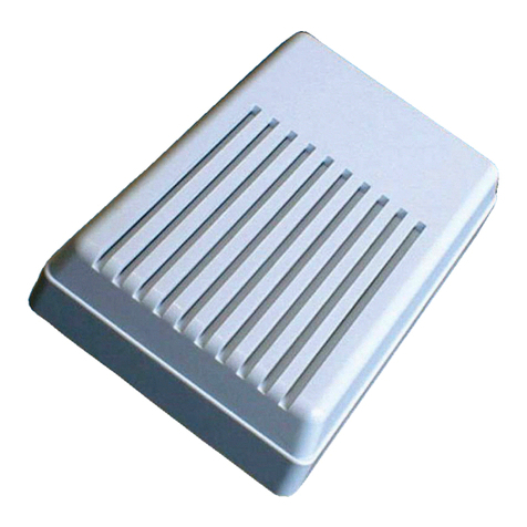
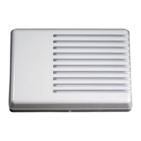
SI500
Indoor Siren NF & A2P EN Grade 2
FEATURES
-High Efficiency Operation
-Silent Start-up
-Selectable sound cut off timer
-Front Tamper
-Max sound output 113 dBA at 1m
-Battery protected via resettable fuse
-Microprocessor controller
-Enclosed electronics module
Compliant with NF EN50131-4:2009, RTC50131-4:2011.
Note: For security reasons the tamper output of the siren is triggered when the siren detects:
- Removal of + ALIM (+ charging supply);
- Removal 0V supply;
Attention: Do not connect + ALIM (14.3V) to the positive output of a power supply which will be
absent during (mains) power failure. ALIM+ must be connected to a permanent power supply.
Elmdene International Ltd Tel. : +44(0)23 9269 6638
3 Keel Close, Interchange Park, Fax : +44(0)23 9266 0483
Portsmouth, Hampshire, PO3 5QD, UK Web : www.elmdene.co.uk

2
Technical Support: 023 9269 6638 PAK200838_03A Feb 2019 ©2019 ELMDENE INTERNATIONAL LTD
OPERATION
The SI500 sounder is used for notification of an alarm condition as generated within an intruder, hold-up
or other alarm system. In response to commands from the alarm system control panel, the SI500 will
emit a high intensity sound.
The SI500 will detect any attempt to gain unauthorised access to the sounder by removal of the cover.
This will generate a tamper signal* which is normally fed back to the alarm control panel.
The SI500 is classified as a self-powered sounder and has an on-board battery which is recharged via the
external power source. This battery is used to operate the sounder if the external power is removed.
The SI500 is designed to sound when the BL+ (Blocage) input is removed or connected to 0V.
* The SI500 is a Security Grade 2 product –loss of ALIM/Hold-off (charging supply) will cause the sounder to self-activate, but a tamper
signal is not generated. A tamper signal is only generated in the event that the cover is unscrewed/removed.
FUNCTIONAL INFORMATION
Tamper Circuit
The SI500 sounder is provided with a tamper output to detect opening of the cover.
(See figure 2 for details of tamper connections.)
TIMER OPTIONS SELECTION
Table 1: Timer Duration Selection Links
KEY
Link FITTED
Link NOT FITTED
Sound Cut-Off Timer
T2
T1
5 sec.*
90 sec.
3 min.
15 min.**
* This cut-off time option intended for installation purposes only.
** Factory default setting.
Response to a fault in the primary power supply (ALIM +/-)
If the primary power supply develops a fault or is deliberately disconnected, the siren is activated for a
time depending on the setting of the ringing time
Sound Cut-off Timer
The SI500 sounder will automatically stop sounding after the time period selected by the Sound Cut-off
Timer link, Table 1, irrespective of the status of the sound trigger (BL+) input. The 5s option is provided
to reduce nuisance noise during testing

3
Technical Support: 023 9269 6638 PAK200838_03A Feb 2019 ©2019 ELMDENE INTERNATIONAL LTD
Fig. 1: SI500 Timer Setting Link Locations and General Connection Information
CONNECTIONS
B+ Positive connection to battery.
B- Negative battery connection. Connect black battery lead after (ALIM) supply is applied.
HP Speaker connections.
ALIM+ Permanent positive hold-off supply
ALIM- Permanent negative hold-off supply.
AP Tamper output - return connections to control panel. (See Figure 2)
BL+ Negative siren trigger, must be held to ALIM+ in standby mode.
Fig. 2: SI500 Connections
Generic control panel
SI500 Siren
AP (Tamper)
BLACK
RED
Tamper Input
0V (ALIM-)
Bell trigger
+14.3V (ALIM+)
B+
B-
AP
AP
BL+
ALIM+
ALIM-
Tamper Input
T2
T1
|+ | + 0v
AP | BL | ALIM

4
Technical Support: 023 9269 6638 PAK200838_03A Feb 2019 ©2019 ELMDENE INTERNATIONAL LTD
INSTALLATION AND CONFIGURATION
1) Select a suitable mounting position for the SI500 sounder.
2) Drill holes as required for fixing the backplate to the wall and for cable entry to the rear of the unit.
3) Route cable from control panel through cable entry aperture.
4) Fit backplate to wall using 4 x M5 fixing screws suitable for material of mounting surface.
Fig. 3: Mounting Diagram

5
Technical Support: 023 9269 6638 PAK200838_03A Feb 2019 ©2019 ELMDENE INTERNATIONAL LTD
1) Fit Timer Option Links - Sounder cut-off timer : T1 & T2 (see table 1).
2) Connect AP (Tamper outputs) as required (see Fig 2)
3) Connect ALIM+ & ALIM-.
4) Apply power to the sounder via ALIM + and ALIM - from control panel.
5) Connect the red and black battery leads to correct terminals of battery.
(NOTE 1: The battery must be installed to permit activation of the siren.
There may be a delay of up to 10s before a valid battery is accepted.
NOTE 2: The SI500 is specified to operate with a Powersonic PS-1221 battery, and it is
recommended to use this battery for optimal performance.)
6) Fully test sounder functionality.
7) Close the sounder cover and check that the AP (tamper) outputs, if used, are closed.
8) Commissioning is complete.
The SI500 sounder should be tested for correct operation on a periodic basis. A minimum of one check
every 12 months is recommended. The following features should be verified on each maintenance visit:
1) Correct operation of sounder from control panel signal
2) Correct operation of cover and rear tampers.
3) Remove the ALIM+ supply from the control panel and check that the internal battery voltage as
measured between B+ and B- is greater than 12V dc. If the battery voltage is less than this value
replace the battery and re-connect observing CORRECT polarity.
BATTERY REMOVAL
The battery may be removed for disposal at end Of product life or if it is detected faulty by the sounder
self-test. To remove, disconnect red and black leads from the battery terminals, unclip rubber retaining
band, and withdraw the battery from its holder. To fit a new battery, insert into holder, and reconnect
positive (RED) and negative (BLACK) leads to correct positive and negative battery terminals.
Refit rubber retaining band.
IMPORTANT: Ensure correct polarity of connections. If either battery lead has become detached from
the terminal block, ensure that exposed battery leads DO NOT accidentally cause a short circuit, then
secure positive (RED) lead to BT+ and negative (BLACK) lead to BT-.
Dispose of used batteries in accordance
with all national and local regulations
COMMISSIONING
MAINTENANCE

6
Technical Support: 023 9269 6638 PAK200838_03A Feb 2019 ©2019 ELMDENE INTERNATIONAL LTD
Table 2: Summary of symptoms and possible faults
Symptom
Fault
Action
Sounder cannot be silenced
BL+ holdoff input is not > 7V
Verify that the control panel is biasing BL+ to
>7V in standby mode.
Holdoff supply (ALIM) is disconnected
or very low
Check integrity of holdoff (ALIM) supply
Sounder stops after 5s
Incorrect timer link setting
Set correct timer jumper links.
Tamper condition indicated
at control panel or cannot
SET control panel
(due to sounder tamper)
Tamper outputs (AP) not connected
correctly to panel.
Refer to connection diagram Figure 2
Tamper switch not closed
Check cover
No response to BL+ input
Battery not connected
Check battery connections to terminal block
Battery faulty or voltage low
Replace battery
Battery charger faulty
Return unit to manufacturer
Audible alarm stops before
timeout.
Battery level very low
Recharge battery
DISPOSAL OF PRODUCT AT END OF LIFE
This product falls within the scope of EU Directives 2012/19/EU Waste Electrical and Electronic Equipment
(WEEE) and 2013/56/EU (Battery). At the end of life, the product must be separated from the domestic
waste stream and disposed via an appropriate approved WEEE disposal route in accordance with all national
and local regulations.
Before disposal of the product, the battery must be removed, and disposed of separately via an appropriate
approved battery disposal route in accordance with all national and local regulations. Package used batteries
safely for onward transport to your supplier, collection point or disposal facility.
Caution: Risk of fire or explosion
if exposed battery wires are allowed to touch.
See Specification for battery type information. The battery is marked with the crossed out wheelie bin
symbol, which may include lettering to indicate cadmium (Cd), lead (Pb), or mercury (Hg).
The packaging supplied with this product may be recycled.
Please dispose of the packaging appropriately.
For more information see: www.recyclethis.info
FAULT FINDING

7
Technical Support: 023 9269 6638 PAK200838_03A Feb 2019 ©2019 ELMDENE INTERNATIONAL LTD
SPECIFICATION
Sound Output > 113 dBA @ 1m
Frequency range ~ 2430 - 3250 Hz
Power Supply 9.0 –15.0Vdc, 14.3Vdc optimal charge
Current Consumption 10mA at 14.3Vdc (quiescent/battery charged)
Battery charging ~100mA when charging fully discharged batteries
Sounding 1.55A max from battery
Cut-off Timer Selectable 5 seconds, 90 seconds, 3 minutes, 15 minutes.
(5 seconds only for installation –not a certified duration)
Batterie 12V 2.1Ah SLA - Battery recharge in less than 24 hours
(Following 10 x 3 minute soundings)
NOTE: The SI500 siren is specified for operation with a
Powersonic PS-1221 battery and it is recommended to use this battery.
Battery Low Voltage Detection 10.9V nominally
Battery Deep DIscharge Protection 9.5V nominal (resulting in de-activation of sounder)
Battery autonomy duration 36h
Tamper detection Cover switch
Tamper Output Max 2A / 30Vdc rated
Sound Trigger Input BL+ < 2.9Vdc.
Dimension / Weight 193mm H x 184mm W x 70mm D / 1.4kg without battery
Fixings M5 self-tapping screws (4-off)
Cover Material Steel
Backplate Material Steel
Protection level IP31 & IK08
Operating Temperature - 10oC to +55oC
Storage Temperature - 10oC to +55oC
COMPLIANCE
This product meets the essential requirements of the following EU Directives:
EMC : 2014/30/EU
RoHS : 2011/65/EU
WEEE : 2012/19/EU
Batteries : 2013/56/EU
LVD : 2014/35/EU
EN50131-4:2009 Security Grade 2, Environmental Class II
RTC50131-4:2011 Security Grade 2, Environmental Class II
CERTIFICATION BODIES
AFNOR Certification CNPP Certification
Tél. : + 33 (0) 1.41.62.80 00 Tél. :+33 (0) 2.32.53.63.63
www.marque-nf.com www.cnpp.com
Certification reference: NF324-H58
Certificate No.: 3130000410
Table of contents
Other Elmdene Marine Equipment manuals