Elmdene INT500 User manual

INT500/INT500S Internal Sounder
with Strobe & Hi/Lo Feature
Note: This unit NOT suitable for external installation
EN50131
-
4: 2009
INT
5
00
INT
5
00S
Po er Source
Remote
Self Po ered
Security Grade
3
2
Environmental Class
II
II
F
EATURES
-
11
0
dB(A) siren output
-Independent lo volume (80dB) output.
-T o selectable tones (fast hoop / arble).
-1W 1Hz Xenon strobe flash.
-12V dc voltage operation
-Polycarbonate cover and backplate
-
2 ay tamper protection: cover, rear
-Negative Tamper return
-Hold-off supply failure detection
-Selectable sound auto cut-off timer
-Full SAB using internal battery (INT500S)
O
PERATION
The INT500 sounder is used for notification of an alarm condition as generated ithin an intruder, hold-up
or other alarm system. In response to commands from the alarm system control panel, the INT500 ill
emit a high intensity sound and/or operate a visual flash.
The INT500 ill detect any attempt to gain unauthorised access to the sounder by removal of the cover, or
any attempt to remove it a ay from its mounting surface. This ill generate a tamper signal hich is
normally fed back to the alarm control panel
The INT500 is classified as an internal remote po ered sounder and is po ered via an external po er
source.
The INT500S is classified as an internal self po ered sounder and has an on-board battery hich is
recharged via the external po er source. This battery is used to operate the sounder if the external po er
to the sounder is removed.
F
UN TIONAL
I
NFORMATION
T
AMPER
IR UIT
Tamper state of the INT500(S) becomes ACTIVE hen front or rear tamper s itch is open, or on loss of H+
or H-.
Elmdene International Ltd
Tel: +44(0)23 9269 6638
3 Keel Close, Interchange Park, Fax: +44(0)23 9266 0483
Portsmouth, Hampshire, PO3 5QD, UK
Web: www.elmdene.co.uk

2
Technical Support: +44(0)23 9269 6638 (option 3) PAK200033_05A Jan 2012 ©2012 ELMDENE INTERNATIONAL LTD
The tamper return output to the control may be configured using link JP1 jumper for either:
-S itched output: Tied to 0V in tamper non-active condition.
HIGH (6.0 - 7.5V) in tamper active condition
-Open collector output: Pulled to 0V hen in non-tamper state
M
ODE
S
ELE TION
JP1 Negative tamper enable.
Link pins 1 & 2 for s itched output (default).
Link pins 2 & 3 for open collector o/p
JP2 Cut-off timer.
Link = no cut-off (default)
No link = sounder cut-off after 15 minutes
JP3 Siren tone.
Link = fast hoop (default)
No link = arble
Figure 1.0 onnections and Jumper Link Options
S
OUND
UT
-O
FF
T
IMER
With the cut-off timer link NOT fitted, the INT500(S) sounder ill automatically stop sounding after 15
minutes, irrespective of the status of the sound trigger (R-) input.
SAB
M
ODE
(INT500S
O
NLY
)
SAB mode is enabled if the internal battery is connected. The siren ill self-activate if either of the
tampers are activated. The INT500S ill also self-activate if the supply lines are cut.
ONNE TIONS
R- Negative siren trigger. Apply 0V to activate sounder
M- Negative lo volume siren trigger (keypad). Apply 0V to activate.
ST- Negative strobe trigger. Apply 0V to activate strobe.
H+ Permanent positive hold-off supply, +12Vdc nominal
H- Permanent negative hold-off supply
RTN Negative tamper return.
BAT- SAB Battery negative
BAT+ SAB Battery positive
OMMISSIONING
1)
Remov
e cover.
2)
Offer backplate to desired position on
mounting surface and drill holes to match
chosen fixing centres.
3)
Fix backplate to mounting surface using
appropriate fixings for the mounting surface.
4)
Set the req
uired Cut
-
off Timer
,
Tamper Return options
and Siren Tone
using JP1
,
JP2
and JP3
.
5)
Loop the connection cable three times through the supplied ferrite as sho n.
6
)
Connect +12V dc and 0V supply from the control panel to H+ and H
-
respectively.
JP3
JP2
JP1
VR1
R- M- ST- H+ H- RTN
BAT+ BAT
-
. .
. .
. . .

3
Technical Support: +44(0)23 9269 6638 (option 3) PAK200033_05A Jan 2012 ©2012 ELMDENE INTERNATIONAL LTD
7)
Conn
ect R
-
to Ring or Bell output of the control panel
and ST
-
to Strobe output (if required)
.
8)
I
f Negative Tamper Return is used, connect RTN to Negative Tamper return on the control panel.
9)
If Lo facility is used, connect M
-
to Keypad Follo or a pro
grammable output from
the
control panel
10
)
For SAB facility (INT
5
00S only) connect the battery ires to BAT+ and BAT
-
, ensuring correct polarity.
NOTE: The unit ill sound until the cover is replaced.
T
ESTING
WARNING:
HIGH
VOLTAGE
–
D
O
NOT
TOU H THE
P B
OMPONENTS WHILE THE STROBE IS
OPERATING
(
OR FOR AT LEAST
1
MINUTE AFTER STROBE SUPPLY IS REMOVED
).
1)
Activate bell or ring output from control panel (R
-
to 0V). Check high volume sound activates.
2)
Activate strobe output from control panel (ST
-
to 0V). Check the strobe activates.
3)
If Lo facility is used, activate keypad on control panel and check lo volume from sounder.
Adjust VR1
for desired Lo volume level.
4)
Remove cover and check high volume from sounder.
(Tamper activation)
5)
If Neg
ative Tamper Return connection is made to the control panel, check that the panel has detected
a tamper condition from step 2)
6)
Replace the cover. Check that the sounder s itches off and the tamper output has cleared.
7)
INT5
00S: Remove H+ supply conne
ction at the control panel. Check high volume from sounder and
tamper or bell failure is detected at the control panel.
8)
INT500S: Replace H+ supply. Check that the sounder s itches off and the tamper output has cleared.
9)
Fasten the cover to the backp
late using the fixing scre supplied.
M
AINTENAN E
This sounder should be tested for correct operation on a periodic basis. A minimum of one check every 12
months is recommended. The follo ing features should be verified on each maintenance visit:
1)
Correct operation of sounder from control panel signals
2)
Correct operation of cover and rear tampers.
3)
Remove the +ve po er supply from the control panel and check internal battery voltage as
measured bet een BAT+ and BAT- is greater than 4.5V dc. If the battery voltage is less than this
value replace internal battery ith similar of 6V 170mAh rating.
4)
Check for signs of significant dust ingress. Clean as necessary.
SAB
B
ATTERY
R
EMOVAL
The SAB battery may be removed for disposal at end of product life. To remove the battery, disconnect
red and black leads from BAT+ and BAT- and unclip battery from holder. To fit a ne battery, clip into
holder and reconnect positive (RED) lead to BAT+ and negative (BLACK) lead to BAT-.
IMPORTANT: Ensure correct polarity of connections and that exposed battery leads DO NOT accidentally
touch.
Dispose of used batteries in accordance with all national and local regulations

4
Technical Support: +44(0)23 9269 6638 (option 3) PAK200033_05A Jan 2012 ©2012 ELMDENE INTERNATIONAL LTD
F
AULT
F
INDING
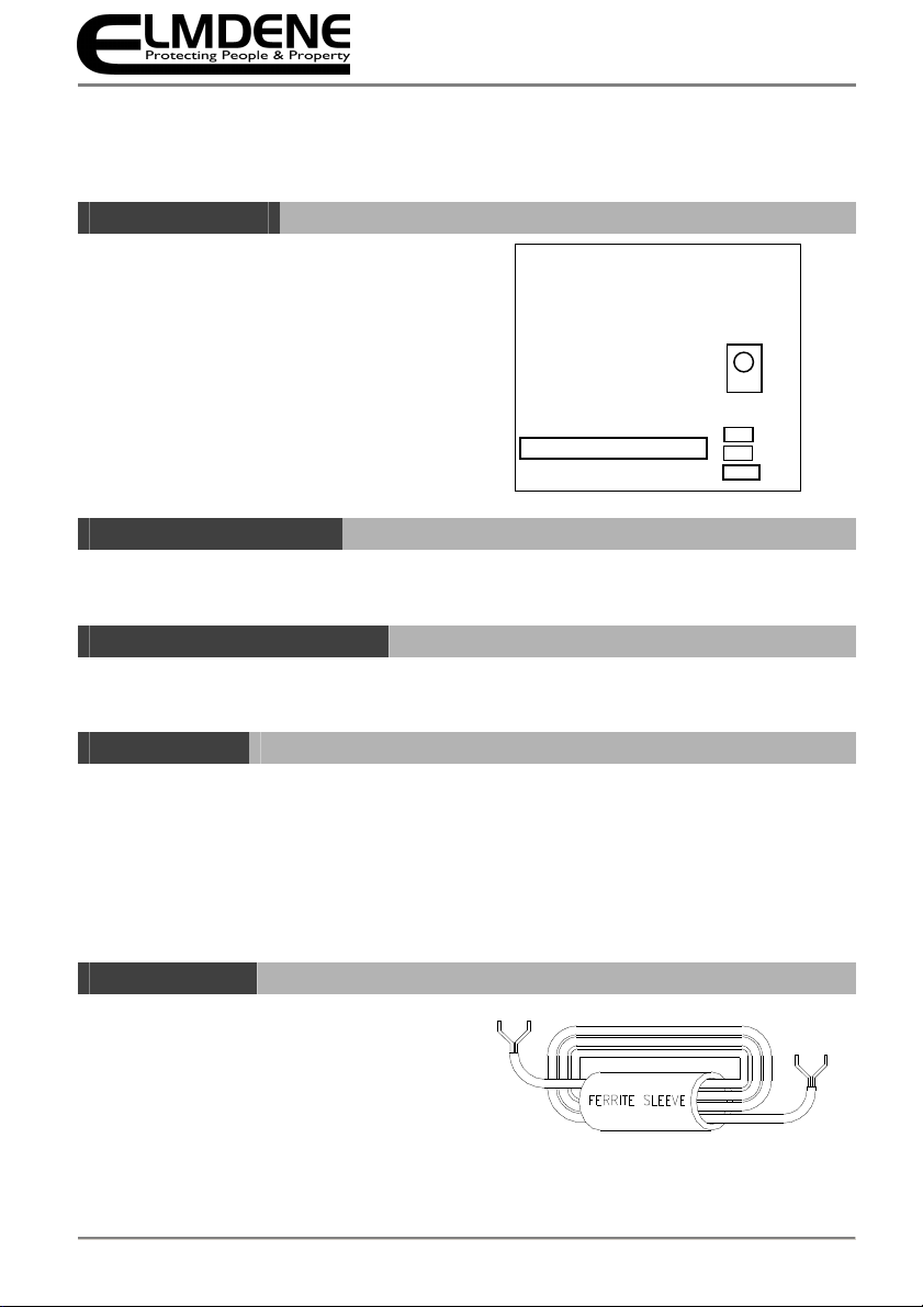
Symptom Fault Action
Sounder activated in non-alarm condition
and tamper sho s at panel
Cover not closed correctly.
Check cover closed and scre secure.
Cannot SET control panel
(due to sounder tamper)
Cover or Rear tamper s itch not
closed. Check cover and rear tamper s itches fully closed.
No H+/H- connection Check po er available on H+/H- connections
D
ISPOSAL OF
P
RODU T AT
E
ND OF
L
IFE
This product falls ithin the scope of EU Directives 2002/96/EC Waste Electrical and Electronic Equipment (WEEE) and 2006/66/CE
(Battery). At the end of life, the product must be separated from the domestic aste stream and disposed via an appropriate approved
WEEE disposal route in accordance ith all national and local regulations.
Before disposal of the product, the SAB battery must be removed and disposed of separately via an appropriate approved battery disposal
route in accordance ith all national and local regulations. Package used batteries safely for on ard transport to your supplier, collection
point or disposal facility.
Caution risk of fire or explosion if bare battery wires are allowed to touch.
See Specification for battery type information. The battery is marked ith the crossed out heelie bin symbol, hich may include lettering
to indicate cadmium (Cd), lead (Pb), or mercury (Hg).
For more information see: .recyclethis.info
S
PE IFI ATION
Siren Output 110dBA peak @ 1m.
Po er supply 10.0 – 14.0V dc, 12V dc nominal
Current Consumption 15mA standby
220mA maximum hen sounding.
65mA maximum hen strobing.
Cut-off Timer Selectable 15 minutes or no cut-off.
SAB Facility 1 x 6V 170mAh NiCd battery, trickle charged from H+ supply
Case Dimensions 160mm x 110mm x 40mm.
OMPLIAN E
This product meets the essential requirements of the follo ing EU Directives:
EMC: 2004/108/EC
RoHS: 2002/95/EC
WEEE: 2002/96/EC
Battery: 2006/66/EC
EN50131-4:2009 INT500 Security Grade 3
INT500S Security Grade 2
Environmental Class II
This product is suitable for use in systems designed to comply ith PD6662:2010 at:
Grade 2 (INT500S) or Grade 3 (INT500) and Environmental lass II.
The packaging supplied with this product may be recycled.
Please dispose o packaging accordingly.
This manual suits for next models
1
Other Elmdene Marine Equipment manuals
Popular Marine Equipment manuals by other brands

Konsberg
Konsberg AIS 200 installation manual

Dometic
Dometic Xtreme NFB SHX7606 Installation and user manual

Federal Signal Corporation
Federal Signal Corporation G-SND instruction manual

CDI
CDI 174-5456 Installation and troubleshooting guide

Garmin
Garmin GC 12 installation instructions

CDI
CDI 113-4985 Installation and troubleshooting guide