Elmdene SABRE 5000 User manual

1
Technical Support: +44(0)23 9269 6638 (option 3) PAK200386_01 March 2019 ©2019 ELMDENE INTERNATIONAL LTD
SABRE 5000 External Sounder
-High Integrity Polished Stainless Steel Cover,
Inner Cover and Backplate
-High Output Siren – 120dB(A) peak
-Integral Strobe – 1 Watt Xenon tube
-High Security Electronics Module Cover
-Microprocessor Controlled
-Active Inrush Current Limit on Strobe, with
Power Save
-Time out of 8 minutes, with 5 seconds
Test Facility
-2-Way Tamper – Cover and Rear
-Conformal Coated Board
-3mm Polycarbonate Lens
-Recharge 2.1 or 7 Ah Battery (Not
included)
Elmdene International Ltd
Tel: +44(0)23 9269 6638
3 Keel Close, Interchange Park, Fax: +44(0)23 9266 0483
Portsmouth, Hampshire, PO3 5QD, UK
Web: www.elmdene.co.uk

2
Technical Support: +44(0)23 9269 6638 (option 3) PAK200386_01 March 2019 ©2019 ELMDENE INTERNATIONAL LTD
The Sabre 5000 sounder is a high specification warning device designed for use in
installations requiring the highest levels of security protection. With its high quality
stainless steel cover the Sabre 5000 is ideal where product integrity is fundamental. The
contemporary appearance of the highly polished cover delivers an aesthetically pleasing
look in every installation.
The Sabre 5000 fully meets the requirements of EN50131-4:2009 as a self-powered
warning device for external applications at Security Grade 2 and Environmental Class IV.
M
OUNTING
Installation should be carried out in accordance with current regulations.
Mounting
Select a suitable position for the siren.
•Find a prominent position to maximise deterrence
•Suitable for cable access and for safe access by ladder for installation
•High enough to deter vandalism and tampering
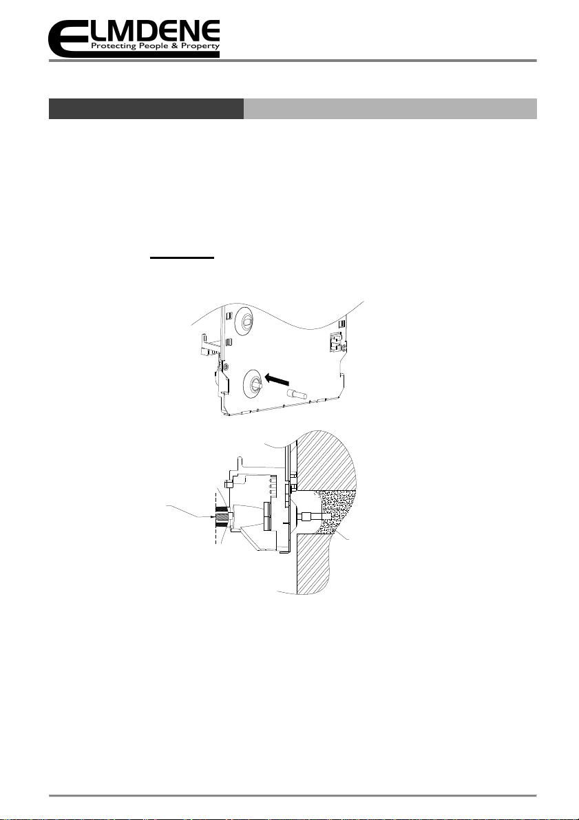
1. Screws holes are provided for wall fixing. The top central hole is a keyhole to
ease mounting and to allow the unit to be levelled before the other holes are
drilled.
2. Drill holes as required for fixing the backplate to the wall and for cable entry to
the rear of the unit.
3. Fit tamper extender (if required) and trim to desired length. See Page 6.
4. Route cable through the entry hole.
5. Elmdene recommends 3 fixings using No. 10 steel screws or as required by
relevant standards.
6. Ensure that the backplate is fixed securely to the wall.
C
OMMISSIONING
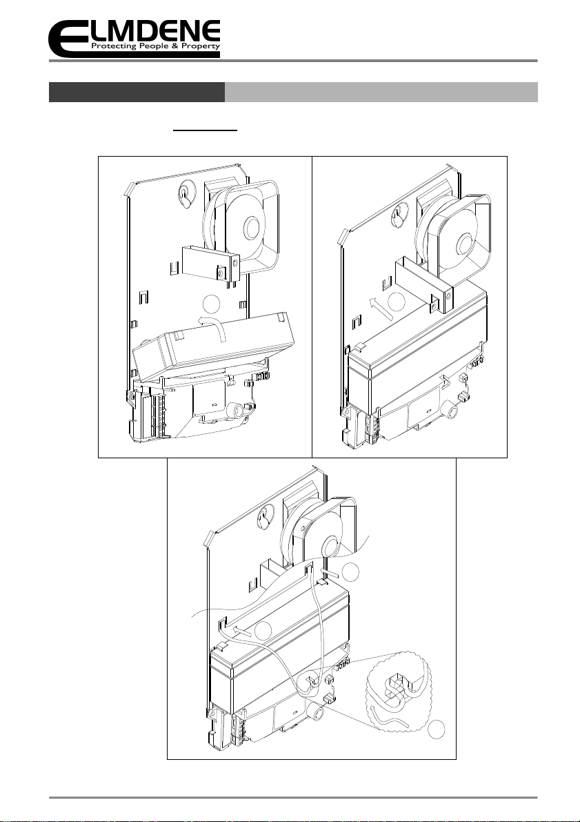
WARNING: Siren may produce high sound pressure levels during
commissioning. Wear hearing protection.
1. Close the 5-second link.
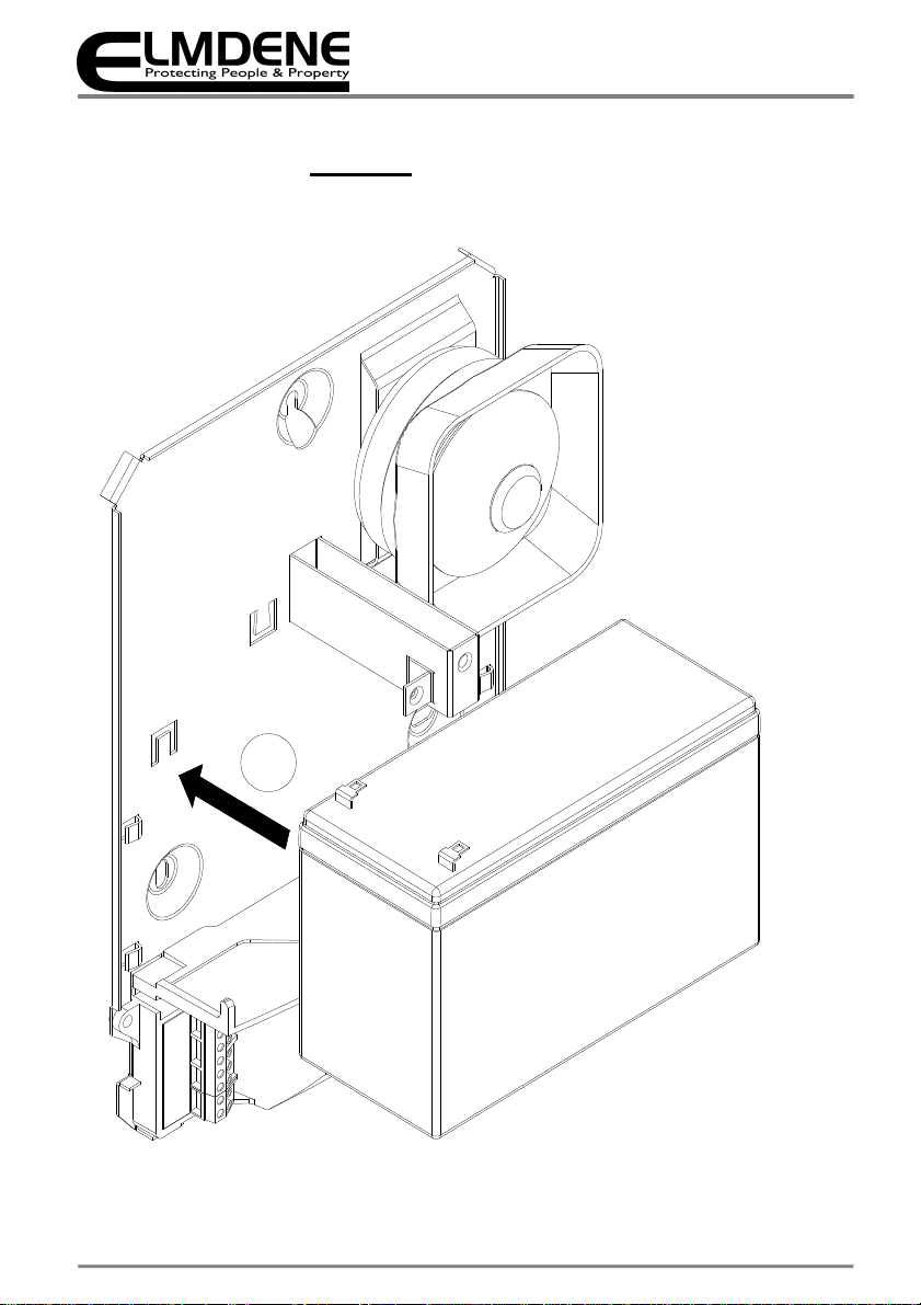
2. Fit “Batt Not Fit” Link OR Connect the Battery: ensure correct polarity.
3. Apply power to Siren via H+ and H- from Control Panel.
4. Strobe will flash until ST– is pulled up to H+
5. The tamper pin may be extended by adding the extender provided on the
module cover.
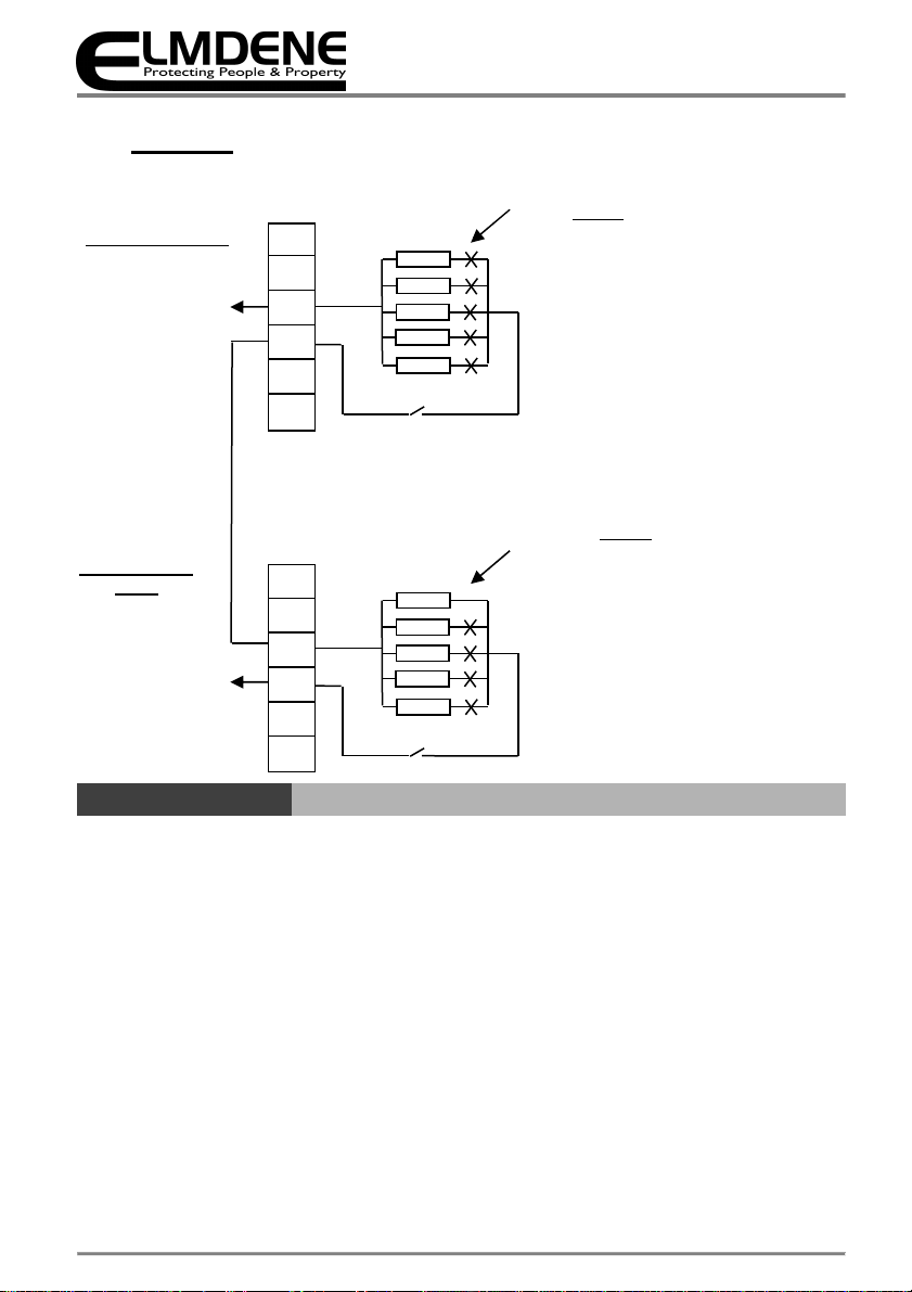
6. Select correct end of line resistor value by cutting all except the resistor value
required.
7. Test sounder by triggering R-.
8. The siren will sound for 5 seconds.
9. Remove 5 second link.
10. Fit the cover.

3
Technical Support: +44(0)23 9269 6638 (option 3) PAK200386_01 March 2019 ©2019 ELMDENE INTERNATIONAL LTD
C
ONNECTION
1. Batt Not Fitted: Fit this link if siren is to be used WITHOUT an internal lead acid
battery. Prevents excessive current draw from the panel.
2. 5 Sec: Fit this link to change the standard 8 minute timeout to 5 seconds for
engineering test.
For End of Line resistor configuration - cut all of the wire links except the link required for
your required resistor value
J
UMPER
S
ETTINGS
W
IRE
L
INK
S
ETTINGS
J9
8 MINS
5 SECS
TIMER
J8
BATT FITTED
BATT
NOT FITTED
BATTERY
J8
J9
SPEAKER
4K7
Ω
-
Green
3K3
Ω
-
Yellow
2K2
Ω
- Red
1K
O - Brown
0O -
Black
ST-
R-
TR
TS
H-
H+
Figure 1 (Connections)
Fit Ferrite loop into all wires
Figure 2—Single Siren Tamper Connection
H+
H
-
TR
TS
R-
ST-
To Control Panel
Tamper I/P
Cut ALL EXCEPT
required terminating
0 R
1K0
2K2
3K3
4K7
Tamper Switch

4
Technical Support: +44(0)23 9269 6638 (option 3) PAK200386_01 March 2019 ©2019 ELMDENE INTERNATIONAL LTD
_ _ _ _ _ _ _ _ _ _ _ _ _ _ _ _ _ _ _ _ _ _ _ _
T
ERMINATIONS
Tamper Switch
End of Line Siren
Cut ALL EXCEPT
0R resistor
0 R
1K0
2K2
3K3
4K7
Tamper Switch
H+
H-
TR
TS
R-
ST-
To Control Panel
Tamper I/P
Cut ALL EXCEPT required
terminating resistor
0 R
1K0
2K2
3K3
4K7
H+
H-
TR
TS
R-
ST-
To Control Panel
Tamper I/P
Figure 3—Multiple Cascade Siren Tamper Connection
First Cascade
Siren
1K0
2K2
3K3
4K7
0 R
H+ Permanent Positive Hold off Supply
H- Permanent Negative Hold off Supply
TS Tamper select. Connect to H- for single unit or last in line.
Connect to TR of next unit for multiple unit installation
TR Tamper return output connection to control panel
R- Negative Ring Trigger
ST- Negative Strobe Trigger
Flying Leads for Battery connection—Ensure correct polarity. Red = +Ve
Black = - Ve

5
Technical Support: +44(0)23 9269 6638 (option 3) PAK200386_01 March 2019 ©2019 ELMDENE INTERNATIONAL LTD
R
EAR
T
AMPER
A
JUSTMENT
1. Hold backplate assembly to wall
2. Push cover tamper pin in until level with bottom of chamfer
3. Lift backplate until tamper ‘clicks’. Rear tamper must activate with 2-3mm of travel
4. Attach tamper extender to rear tamper pin if required
5. Trim rear tamper extender and repeat steps 2-5 until correct operation achieved
Push pin into
moulding (using
finger)
TrimPin To
Correct Length
Attach Tamper
Extender
Figure 4—Rear Tamper Adjustment

6
Technical Support: +44(0)23 9269 6638 (option 3) PAK200386_01 March 2019 ©2019 ELMDENE INTERNATIONAL LTD
B
ATTERY
I
NSTALLATION
2
4
3
5
1
Figure 5—Fitting 2.1AH Battery

7
Technical Support: +44(0)23 9269 6638 (option 3) PAK200386_01 March 2019 ©2019 ELMDENE INTERNATIONAL LTD
1
Figure 6 - Fitting 7AH Battery

8
Technical Support: +44(0)23 9269 6638 (option 3) PAK200386_01 March 2019 ©2019 ELMDENE INTERNATIONAL LTD
M
AINTENANCE
1
2
5
3
Disconnect
Disconnect
4
Figure 7 - Electronics Module Removal

9
Technical Support: +44(0)23 9269 6638 (option 3) PAK200386_01 March 2019 ©2019 ELMDENE INTERNATIONAL LTD
2
5
4
1
3
6
7
Figure 8—Loud Speaker Removal

10
Technical Support: +44(0)23 9269 6638 (option 3) PAK200386_01 March 2019 ©2019 ELMDENE INTERNATIONAL LTD
T
ECHNICAL
S
PECIFICATION
Parameter
Typical Values
Environmental
Sounder Volume 120 dB(A) peak
Cut off Timer 8 minutes ma (5 second test)
Waterproofing All electronics conformal coated
Operating Temp -25 to + 55 °C
Storage Temp -25 to + 70 °C
Electrical
Supply Voltage 9—15V d.c. (13.8 –14.2V for optimal battery charging)
Current 17 mA quiescent
Sounder 400 mA Sounder Ma
Strobe 100 mA
Battery Type Sealed Lead Acid
Battery Voltage 12.0V
Battery Capacity 2.1 or 7 Ah
Strobe Rating 1 Watt
Strobe Flash Rate 1 Hz reduces to 1/2 Hz after 15 mins.
Stops after 24 hours
Physical
Material Stainless Steel Backplate, cover and inner cover.
3mm Polycarbonate— lens and module cover
Tamper Detection
Cover and Rear
Kinetic Protection IK08
Size 260 185 90
Weight 2.3Kg
Ingress Protection IP35

11
Technical Support: +44(0)23 9269 6638 (option 3) PAK200386_01 March 2019 ©2019 ELMDENE INTERNATIONAL LTD
C
OMPLIANCE
This product meets the essential requirements of the following EU Directives:
EMC: 2014/30/EU
RoHS: 2011/65/EU
WEEE: 2012/19/EU
Battery: 2013/56/EU
EN50131-4:2009 Security Grade 2
Environmental Class IV
This product is suitable for use in systems designed to comply with PD6662:2017 at:
Grade 2 and Environmental Class IV.
The packaging supplied with this product may be recycled.
Please dispose of packaging accordingly.
Table of contents
Other Elmdene Marine Equipment manuals