Elmdene VERTEC-3000-G3 User manual

Technical Support Line +44 (0)23 9269 6638 (Option 3) PAK200218 ss 05B Oct 2012 ©2012 ELMDENE NTERNAT ONAL LTD
VERTEC-3000-G3 External Grade 3 Sounder
F
EATURES
-
105
dB(A) siren output
-12v dc voltage operation
-ntegral 1.0 Watt Xenon tube strobe (with
active inrush current limit)
-3 way tamper protection: cover, rear & module
-Separate sound and strobe trigger inputs
-Hold-off supply failure detection
-Battery and piezo test with fault output
-Remote test input facility
-Selectable sound auto cut-off timer: no cut-off,
5s (for test), 3, 10, 15 minutes
-
Full SAB using internal batt
ery
-Twin Comfort LEDs selectable on, off, alternate
flash
-4 selectable sound tones
-Audible Tamper to assist commissioning
-Ring Line Monitoring
-Fully enclosed electronics module
-Engineer Mode for quiet installation and
maintenance
-Polycarbonate cover and backplate
-Microprocessor controlled
Elmdene International Ltd
Tel: +44(0)23 9269 6638
3 Keel Close, Interchange Park, Fax: +44(0)23 9266 0483
Portsmouth, Hampshire, PO3 5QD, UK
Web: www.elmdene.co.uk
Figure 1:
Vertec 3000
Module

Technical Support Line +44 (0)23 9269 6638 (Option 3) PAK200218 ss 05B Oct 2012 ©2012 ELMDENE NTERNAT ONAL LTD
O
PERATION
The Vertec 3000 is used for notification of an alarm condition as generated within an intruder, hold-up or other alarm
system. n response to commands from the alarm system control panel, the sounder will emit a high intensity sound
and/or operate a visual flash.
The sounder will detect any attempt to gain unauthorised access to the sounder by removal of the cover, or any attempt
to remove it away from its mounting surface. This will generate a tamper signal which is normally fed back to the alarm
control panel. ntegrity of the Trigger Command (Ring Line) connection is constantly monitored and will cause the unit to
self activate if loss of connection is detected.
These sounders are classified as self powered sounders and have an on-board battery which is recharged via the external
power source. This battery is used to operate the sounder if the external power is removed. The sounders will self actuate
in the event that a tamper condition is detected or the external power to the sounder is removed.
Every 24 hours the sounder performs a self test to check the integrity of its on-board battery, its battery charging circuit
and its piezo transducers. f an error condition is detected, a fault signal is generated. This is normally connected back to
the control panel. This self-test can be triggered at any time by a Remote Test command sent from the control panel.
To assist with commissioning, the sounders have an Engineer Mode to provide silent start-up and Tamper Tones that
indicate the correct closure of the tamper detection switches.
Two Comfort LEDs are used to provide a heart-beat type visual indication when the sounder is not sounding. These may
be disabled.
F
UNCTIONAL
I
NFORMATION
Tam er Circuit for Single or Multi le Cascade Installations
For a single siren installation, link TS to H- and connect TR to the control panel Tamper return input. n cascade
installations with two or more sounders, the TS (Tamper Source) will normally be connected to the TR (Tamper Return) of
the next sounder, except for the last unit which will have TS linked to H- .
Engineer Mode
This selects silent start-up and silent maintenance. The ENG input may be brought back to the control panel and
connected to a programmable output. Switching this control panel output high when maintenance is required will prevent
the sounder from self activating when the cover is removed or R- activated. The Tamper output is open when ENG is high;
this prevents inadvertent system setting with the sounder left in Engineer Mode.
Self Test and Fault Out ut
The sounder performs a self test every 24 hours. This function tests the condition of the battery and piezo sounders. f a
fault is found the Healthy/Fault output will open.
The Fault output will be cleared (output closed) when:
- the fault has been cleared, e.g. battery (re)connection
- the fault has been cleared and the sounder performs its next 24hour self test
- the fault has been cleared and a self test is triggered using the Engineering Remote Test input
- the fault has been cleared and the sounder has been disconnected from H+ AND the SAB battery has been disconnected
(hardware reset)
Remote Test
Taking the Engineer/Remote Test input high will force a self test. The Healthy/Fault output is immediately opened to
acknowledge receipt of the Remote Test instruction. The condition of the piezos and battery is immediately tested. Any
fault found will be indicated by the Healthy/Fault output remaining open after 10s. The Healthy/Fault output will remain
open until the fault has been cleared and another Self Test or Remote Test has been performed. f the self test has passed,
the Healthy/Fault output will close after 10s of starting the Remote Test.
2

Technical Support Line +44 (0)23 9269 6638 (Option 3) PAK200218 ss 05B Oct 2012 ©2012 ELMDENE NTERNAT ONAL LTD
O
PTIONS
S
ELECTION
Figure 1: Connections and Jumper Link Options
Note: Factory Default is 15 minute Cut-off, flashing LED’s, SAB Mode, Tone 4
Sound Cut-off Timer
The sounder will automatically stop sounding after the time period selected by the Sound Cut-off Timer links, J1/J6,
irrespective of the status of the sound trigger (R-) input. The 5s option is provided to reduce nuisance noise during testing.
Comfort LEDs
Twin comfort LEDs may be configured for alternate flashing, permanently on or permanently off by selection of J2/J7. When
enabled, the LEDs flash at a rate of approximately 1Hz.
SAB Mode
n SAB mode the sounder can draw current from both the control panel and the battery. The siren will self-activate if either of
the tampers are activated.
n SCB mode the sounder draws the majority of its current from the battery to minimise drain on the control panel. This allows
the user to connect multiple units to a control panel without overloading it. Select SCB mode using the J8 link (Figure 2.0). n
this mode the sounder will NOT self activate under a tamper condition but the tamper condition will still be signalled back to
the control panel. The control panel can then trigger the siren using the R– line.
Note: The siren will self-activate if the supply lines are cut in either mode.
T ME
R
LEDS
J1
J6
J2
J7
EN
G
HEALTHY
SAB
S
C
B
J4 J5
TONES
J8
H+
H
-
R
-
ST-
TS
TR
BAT+
BAT
-
3
J1
2
TONES (J4/J5)
3 41
J6
TIMER
LEDS
10m
3m
5s
J2 J7
15m ON
OFF
FLASH
OFF

Technical Support Line +44 (0)23 9269 6638 (Option 3) PAK200218 ss 05B Oct 2012 ©2012 ELMDENE NTERNAT ONAL LTD
C
ONNECTIONS
ENG Optional engineer input for quiet operation
during installation/ maintenance.
HEALTHY
(x2)
Volts free siren Healthy/Fault output - normally closed (Healthy)
H+ Permanent Positive Hold off Supply TS Tamper select. Connect to H- for single unit or last in line. Connect
to TR of next unit for multiple unit installation (see Figure 4.0)
H- Permanent Negative Hold off Supply TR Tamper return connection to control panel
R- Negative Siren Trigger BAT+ Positive connection to battery
ST- Negative strobe Trigger and Supply BAT- Negative battery connection. Connect black battery lead after
applying power.
Panel First /Only unit Last unit
(Furthest from panel)
0V Strobe
Trigger
Fault i/p
Fault i/p
+12V
0V
Tamper
Return
0V Siren
Trigger
Prog o/p
H+
H-
TS
TR
R-
ST-
ENG
Healthy
Healthy
H+
H-
TS
TR
R-
ST-
ENG
Healthy
Healthy
Figure 3: Multiple cascade siren connections
0V Strobe
Trigger
Fault i/p
Fault i/p
H+
H-
TS
TR
+12V
0V
Tamper
Return
0V Siren
Trigger
Prog o/p
R-
ST-
ENG
Healthy
Healthy
Figure 2: Single siren connections
Note 1:
Where the siren Trigger is not pulled up to > +8.5V by the
control panel when in standby mode, or is operated via
volt free contacts, it will be necessary to fit a pull up
resistor (1k0) as shown, at the control panel to enable
monitoring of the Trigger connection.
4
See Note 1
See Note 1

Technical Support Line +44 (0)23 9269 6638 (Option 3) PAK200218 ss 05B Oct 2012 ©2012 ELMDENE NTERNAT ONAL LTD
I
NSTALLATION AND
S
ET
-U
P
1. Remove cover, undo module fixing screw and swing electronics module away from backplate. Module will self support
when pivots are pushed back in their pivot slots
2. Offer backplate to desired position on mounting surface and drill holes to match chosen fixing centres and rear tamper
insert. A minimum of three fixings should be used.
3. Pierce cable grommet (supplied) to match diameter of control panel cable. Grommet must be used to prevent water
ingress via cable.
4. Fix grommet to backplate and pass control cable through grommet.
5. Fix backplate to mounting surface using appropriate fixings for the mounting
surface.
6.
Fix tamper insert to mounting surface using an appropriate fixing for the
mounting surface
7. Swing electronics module onto backplate and verify that rear tamper pin is
depressed when in contact with the tamper insert.
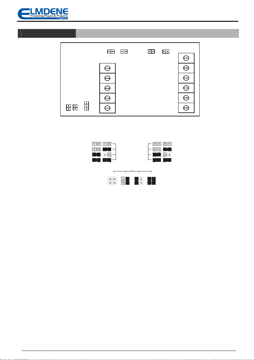
8. Set the required Cut-off Timer (J1 & J6), LED option (J2 & J7), Tone options
(J4 & J5) and SAB/SCB option (J8).
9. Connect ENG input to H+ or to a switched output of control panel set high.
10. Make remaining connections to control panel in the following order:
sounder activate, strobe activate, tamper return, negative power supply,
positive supply.
11. Connect the black battery lead to BAT-.
12. Disconnect ENG from H+.
13. Lower inner cover and fix using self tapping screw supplied.
14. Replace cover temporarily. Sounder should stop when cover completely replaced.
T
ESTING
1. Activate bell or ring output from control panel. Check sounder activates.
2. Activate strobe output from control panel. Check strobe flashes.
3. Ensure control panel bell and strobe outputs are switched off. Remove cover and check sounder operates due to top
tamper.
4. f a Tamper Return connection is made to the control panel, check that the panel detects a tamper active condition.
5. Temporarily replace cover. Check that sounder switches off. Check that the tamper active condition has cleared at the
control panel.
6. Unfasten inner cover fixing screw so that module sits away from wall mounting and rear tamper is activated. Temporarily
replace cover and check that sounder activates. Check that a tamper active condition is detected at the control panel.
7. Push cover and module into its fully seated position closing the rear tamper pin. Check that sounder switches off and that
the tamper condition is cleared at the control panel.
8. Securely fasten inner cover retaining screw.
9. Remove +ve sounder power supply connection at control panel. Check sounder activates and a tamper active condition is
detected at the control panel.
10. Replace +ve sounder power supply. Check tamper active condition is cleared at control panel.
11. Remove -ve sounder power supply connection at control panel. Check sounder activates and a tamper active condition is
detected at the control panel.
12. Replace -ve sounder power supply. Check tamper active condition is cleared at control panel.
13. Disconnect R- at control panel, check that the siren activates
14. Check correct operation of comfort LEDS.
15. Fasten cover to backplate using two fixing screws supplied. Fit screw covers.
16. Testing complete.
M
AINTENANCE
1. The sounder should be tested for correct operation on a periodic basis. A minimum of one check every 12 months is
recommended. The following features should be verified on each maintenance visit:
2. Correct operation of sounder and strobe from control panel signals
3. Correct operation of cover and rear tampers.
5
Figure 4: Tamper insert
mounting
Table of contents
Other Elmdene Marine Equipment manuals