manuals.online logo
Brands
  1. Home
  2. •
  3. Brands
  4. •
  5. Elmdene
  6. •
  7. Power Supply
  8. •
  9. Elmdene 2402STE User manual

Elmdene 2402STE User manual

Technical Support Line +44 (0)23 9269 6638 2402STE PAK200480 Issue 01H May 2016 Page 1 of 4
ELMDENE INTERNATIONAL LIMITED
3 KEEL CLOSE
INTERCHANGE PARK
PORTSMOUTH
HAMPSHIRE
PO3 5QD, UK
TEL: +44 (0) 23 9269 6638
FAX: +44 (0) 23 9266 0483
www.elmdene.co.uk
2402STE Intelligent Switch Mode Powe
r Supply: EN54
-
4 Certified
27.6Vdc 2A PSU with Intelligent Battery Charging, Monitoring and Remote Fault Signalling
O
VERVIEW
The 2402STE is a fully featured EN54-4 approved power supply ideal for use in Fire Systems and Access control applications. Its
regulated 27.6V dc output will supply up to 2A continuous into the load, in addition to providing up to 0.8A for charging the standby
batteries. The power supply output features electronic short circuit protection under both mains and standby battery operation.
Maximum battery life is assured through continuous active battery monitoring and the use of a three stage charger, comprising bulk,
absorb and temperature compensated final float phase depending upon battery condition. Deep discharge protection prevents
premature battery failure when operating from standby for extended periods. Two sets of volt free solid state relay fault output signal (i)
loss of mains and (ii) battery fault, charger fault and loss of output.
•Certified by VdS to EN54-4:1997 +A1: 2002 + A2: 2006
•2A current to load at 27.6V dc nominal regulated output
•Electronic overload protection shuts down output until overload or short circuit is removed
•Battery Monitor detects battery missing, low battery, short-circuit or reverse connection
•Battery charging circuit is energised only when a battery is correctly connected and the battery voltage is greater than 14V
•No loss of output during automatic connection of battery to load on loss of mains
•Deep discharge protection disconnects battery from load when battery voltage falls to 21V
•Automatic start-up on battery only
•Fault indicator LED (Red) flashes on detection of output fault, battery fault, charger fault and mains failure
•Mains indicator LED (green) showing mains present
C
OMPLIANCE
This power supply unit complies with the following European Directives:
Low Voltage 2014/35/EU EMC 2014/30/EU WEEE 2012/19/EU RoHS2 2011/65/EU CPR305/2011 EU
S
PECIFICATION
Input
Voltage 93Vac minimum, 264Vac maximum
Frequency 45Hz – 65Hz
Current 1.25A maximum for a 2A load and 0.8A battery charging
Inrush current 30A maximum @ 25
O
C, 110Vac for 10ms
Mains input fuse T3.15A 20mm, 250Vac HBC
Output
Voltage 26.0Vdc – 28vdc on mains power / 18Vdc – 26Vdc on battery standby
Load Current 0 - 2A
Ripple 100mV max over full rated mains voltage
Load output fuse T2A 20mm, 250Vac glass
Overload Electronic shutdown at 4.5A until overload or short circuit removed
Standby Battery
Battery Capacity 2 x 17Ah maximum (e.g. Yuasa NP17-12) series connected
Battery fuse protection T2A 20mm glass
Battery Charging Constant current (0.8A) bulk charging to 80% within 24 hours, float charging to 100% within 48
hours
Low Battery Threshold Voltage 23V nominal
Deep discharge protection Battery disconnect at 21V nominal
Quiescent current - no load 25mA nominal
Quiescent current - battery cut off <70µA
Mechanical
Case material 1.2mm steel, white powder coated
Size 400mm W x 420mm H x 80mm D
Weight 6.2kg (excluding batteries)
Environmental
Temperature -10 to +40
O
C (operating) 95% RH non-condensing
-20 to +80
O
C (storage)
C
ONNECTIONS
O/P + and - Voltage output to load
PSU Fault Solid State Relay output contacts
EPS fault Solid State Relay output contacts
Temp sensor Connection to battery temperature sensor
BATT + and - Connections to standby batteries
FAN + and - No Connection
VdS
G209142
09
0786
-
CPD
-
20787
Technical Support Line +44 (0)23 9269 6638 2402STE PAK200480 Issue 01H May 2016 Page 2 of 4
F
EATURES
Loss of Mains and Brown-out compensation
If the mains input has been lost for greater than 10s, a Loss of Mains condition is detected, an EPS Fault is signalled and the green Mains LED is
extinguished. Short duration mains “brown-out” conditions are not signalled thus reducing nuisance alarms. The red Fault LED will show a heart-
beat pulse indicating that the PSU is operating correctly in standby mode.
Standby Operation
When the mains input is lost, the power supply will automatically switch to the standby batteries and provide uninterrupted power the connected
load whilst there is capacity in the standby batteries. The front panel Fault LED is pulsed periodically to indicate that the PSU is healthy and
operating in standby mode.
During standby operation, the standby battery voltage is continually monitored. Once this drops below the Low Battery Voltage threshold
(approximately 23V), a PSU Fault signal is generated and a Low Battery condition is signalled on the front panel LED.
Battery Management
The standby batteries are tested regularly. If a battery becomes disconnected, a PSU Fault signal will be generated within 20s of the
disconnection.
If the impedance of the battery circuit connections increases above 500mΩ, for example due to corrosion or damage to the cabling, a PSU Fault
signal will be generated within 60 minutes.
If the battery is unable to supply significant current to the load, for example due to cell degradation, a PSU Fault signal will be generated within 24
hours.
Battery Charging
The standby batteries are charged automatically when the mains is present. The PSU uses a fast bulk charge regime to quickly recharge the
batteries to approximately 80% capacity followed by a reduced charging current to reach full capacity. The batteries are held at full capacity using
a temperature compensated float regime. The battery temperature is measured at its terminals using a special sensing probe. An extended probe
may be fitted for use with an external standby battery pack.
Note: if the batteries are disconnected the battery charger is switched off and there will be NO measurable voltage at the BATT terminals.
Battery Auto-Start
The power supply will self-start if a set of charged standby batteries are connected without any mains present. An EPS Fault signal will be
generated under this condition.
Note: a pause of 5s must be observed between repeated battery connections and disconnections to guarantee an auto-start.
S
IGNALLING
Fault Outputs:
100mA @ 60Vdc solid state relay (Open indicates fault condition)
EPS Fault PSU Fault Condition Possible Cause Action
C
LOSED
C
LOSED
Normal operation Mains present
Battery fully charged
None
O
PEN
C
LOSED
Standby Mode Mains lost
Battery driving load
Investigate loss of mains
C
LOSED
O
PEN
Fault Present Blown fuses
Battery fault
Overload
Internal fault
Investigate fault source using
diagnostic LED
Rectify fault where possible
O
PEN
O
PEN
PSU Shutdown Mains lost
Standby battery exhausted
Restore mains as soon as
possible
Local Indicators – front panel
Red LED
Fault
Green LED
Mains Condition Possible Cause Action
O
FF
O
N
Normal operation Mains present
Battery fully charged None
F
LASH
C
ONTINUOUS
O
N
or
O
FF
Fault
Blown fuses
Battery fault
Overload
Internal fault
Contact service engineer
1
P
ULSE
O
FF
Standby Mode Mains lost
Battery driving load Investigate loss of mains
Diagnostic Indicator – internal
Red LED
Diagnostic
Green LED
Mains Condition Possible Cause Action
O
FF
O
N
Normal operation Mains present
Battery fully charged None
O
FF
Standby Operation Mains Lost. No faults present
Battery driving load Investigate loss of mains
O
N
C
ONTINUOUS
O
N
or O
FF
Internal Fault Software fault detected
PSU running in Safe Mode Return to manufacturer
F
LASH
C
ONTINUOUS
O
N
or O
FF
No output
Output fuse blown
Output overload
Output short circuit
Check and replace output fuse
Disconnect output load and test load
1
P
ULSE
O
N
Battery Charging
No faults active
Battery charging normally but
< 90% of full charge
None
2
P
ULSES
O
N
No Battery
Battery disconnected
Battery fuse blown
Battery heavily discharged
Check battery connections
Check and replace battery fuse
Check battery terminal voltage and replace if
battery aged
O
FF
Low Battery Volts Standby Mode
Battery almost discharged Restore mains as soon as possible
3
P
ULSES
O
N
or O
FF
Battery Fault High impedance in battery connection
Battery internal fault
Check battery connections for damage e.g.
corrosion. Replace battery if aged
4
P
ULSES
O
N
or O
FF
Charger Fault Internal failure of battery charger Return to manufacturer
5
P
ULSES
O
N
or O
FF
Battery Temperature Probe
Fault
Battery temperature monitor
disconnected or damaged
PSU running in Safe Mode
Check temperature sensor connections and
condition of sensor and cable
Replace if suspect
Technical Support Line +44 (0)23 9269 6638 2402STE PAK200480 Issue 01H May 2016 Page 3 of 4
I
NSTALLATION
This unit is only suitable for installation as permanently connected equipment. The PSU is NOT SUITABLE for external installation.
This unit must be fed from a mains power source having a separate (approved) disconnect device and fitted with a fuse or other over-current
protection device rated at 3A maximum. Ensure that the disconnect device used has appropriate earth fault protection to the applicable standard.
Where the PSU is used to provide power to a fire alarm circuit, the mains isolation and disconnect device should be provided solely for this
purpose and be suitably marked “FIRE ALARM – DO NOT TURN OFF”. All cabling should meet national and local fire system installation
regulations, e.g. FP200 type cable for high integrity installations.
Where the PSU is used for other applications, it should be installed according to all relevant safety regulations applicable to that application.
Where the PSU Fault and EPS Fault outputs are used, they should only be connected to circuits having voltages less than 60V dc.
Cable Sizing
1) Mains input cable must be to the applicable standard with a 3A or greater current capacity, i.e. 0.5mm
2
nominal conductor area, having a
minimum operating voltage of 300/500 Vac.
2) The low voltage output cable must be sized to carry the rated load current to the devices connected to the PSU.
3) Mains input and low voltage output cables should be routed to use different entry / exit holes in the case. Bushes should be used to
protect cable sheaths from chafing. Ensure that these bushings are correctly sized (i.e. close fitting with respect to cable sizing). Note
that the bushes should meet a minimum flammability specification of UL94 HB.
4) All cabling should be securely fastened in position using a cable tie through the saddles provided.
Mounting
5) Fix to wall or other support structure in correct orientation i.e. with hinge on left hand side, using screws of sufficient size and length
through the mounting holes.
6) PSU should be mounted no further than 10cm from the control and indicating equipment, close coupled by conduit.
7) Knock-outs are provided in the case for mating with external trunking or conduit.
8) Ensure that all unused holes (on the rear of the case) are sealed to prevent the ingress of damp and dust.
C
OMMISSIONING
Mains Power Up
1) With no external connections made to the PSU, connect the mains input wires to the terminal block, ensuring that the mains isolator
(disconnect device) is open. Fasten wiring in place with cable tie to saddle. Note: Equipment must be earthed.
2) Apply mains input. Ensure that the green Mains LED illuminates and that the red Fault LED flashes after approximately 20s (indicating a
disconnected battery).
3) Disconnect the mains power.
Load Output and Remote Signalling
4) Connect the EPS and PSU Fault outputs to the appropriate inputs of control equipment if remote fault monitoring is required.
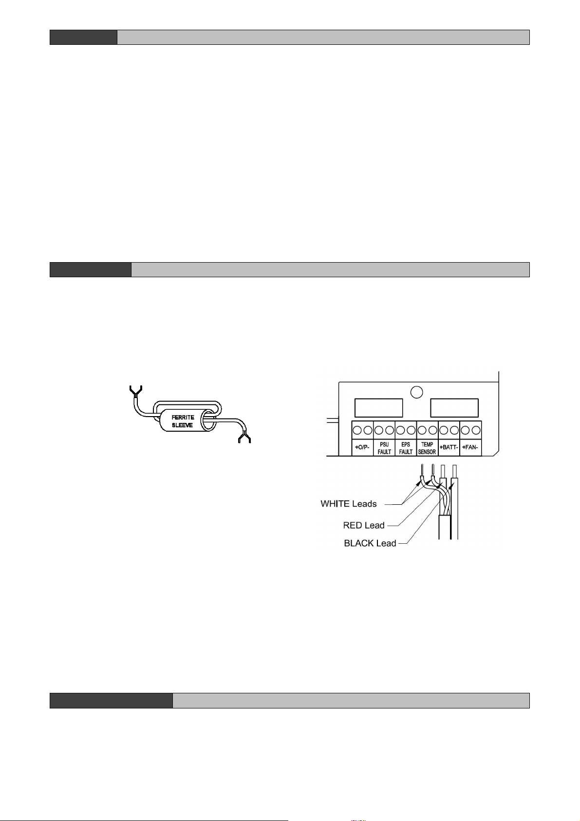
5) Loop the load (output) wiring through the supplied ferrite EMC suppressor as shown in Figure. 1. Cable tie to saddle provided (adjacent
to exit hole).
6) Re-apply mains. Verify that the green Mains LED illuminates and the red
Fault LED flashes after approximately 20s (disconnected battery).
7) If connected, verify that the EPS Fault monitor shows a closed contact
and the PSU Fault monitor shows an open contact.
8)
Perform a full functional test of system including full alarm condition
.
Standby Battery
9)
Mount two 12V 17Ah batteries in lower part of enclosure.
10) Connect the two 12V standby batteries in series using the single cable
provided. Connect the negative of one battery to the positive of the other.
DO NOT CONNECT the other two battery terminals to each other.
11) Connect the free Positive and Negative terminals of the batteries to the
PCB terminals Batt+ and Batt - using the cables provided. See Figure 2.
12) Ensure the temperature sensor and battery connections are made according to figure 2.
13) Verify that the red Fault LED stops flashing after about 20s (battery connection detected). Verify that the remote PSU Fault monitor
shows a closed contact.
14) Disconnect the mains power. Verify that the green Mains LED extinguishes and the red Fault LED starts to pulse (indicating that the
PSU is running from its standby batteries).
15) If connected, verify that the EPS Fault monitor shows an open contact and the PSU Fault monitor shows a closed contact.
16) Perform a full functional test of system including full alarm condition. Verify that the standby batteries can support the system load. Note:
ensure batteries have sufficient charge.
Final
17) Reconnect the mains. Verify that the green Mains LED illuminates and the red Fault LED extinguishes.
18) If connected, verify that the EPS Fault monitor shows a closed contact and the PSU Fault monitor shows a closed contact.
19) Close cover and secure using fastening screws provided.
O
PERATING
I
NSTRUCTIONS
This unit is intended for use by Service Personnel only. There are NO USER SERVICEABLE parts inside.
The green Mains LED will be illuminated whilst the mains supply is present. In the event of a failure, the red Fault LED will flash and the solid
state remote fault output contacts will open.
Figure 1 - Ferrite EMC suppressor
Figure 2
–
C
onnection of battery leads
and temp sensor to terminal block.
Technical Support Line +44 (0)23 9269 6638 2402STE PAK200480 Issue 01H May 2016 Page 4 of 4
Maintenance
There is no regular maintenance required of the PSU as the microcontroller performs regular health checks of the battery and output voltage.
However, reference should be made to the battery manufacturer’s documentation to determine typical / expected battery life with a
view to periodic replacement of the battery.
If the output of the PSU fails the cause of the failure should be investigated e.g. short circuit load, connection of a deeply discharged battery. The
fault should be rectified before restoring power to the PSU. The following fuses may need to be replaced. Ensure the correct fuse rating and type
is used.
Load Output Fuse T2A 20mm, 250Vac glass
Internal Mains Fuse T3.15A 20mm, 250Vac HBC
Battery Fuse T2A 20mm, 250Vac glass
CAUTION
Risk of explosion if battery is replaced by an incorrect type. Dispose of used batteries according to
the battery manufacturer’s instructions and all local and national regulations
The packaging supplied with this product may be recycled. Please dispose of packaging accordingly.

Other Elmdene Power Supply manuals

Elmdene G1380xN-y-s Series User manual

Elmdene

Elmdene G1380xN-y-s Series User manual

Elmdene 2405ST Series User manual

Elmdene

Elmdene 2405ST Series User manual

Elmdene STX2401-MOD User manual

Elmdene

Elmdene STX2401-MOD User manual

Elmdene G240 N Series User manual

Elmdene

Elmdene G240 N Series User manual

Elmdene STX2410-H User manual

Elmdene

Elmdene STX2410-H User manual

Elmdene 2401ST User manual

Elmdene

Elmdene 2401ST User manual

Elmdene GEN2-08 Series User manual

Elmdene

Elmdene GEN2-08 Series User manual

Elmdene G2410BMU User manual

Elmdene

Elmdene G2410BMU User manual

Elmdene LPS-12-G2 Instruction Manual

Elmdene

Elmdene LPS-12-G2 Instruction Manual

Elmdene G1380xBM Series User manual

Elmdene

Elmdene G1380xBM Series User manual

Elmdene STX2402-MOD User manual

Elmdene

Elmdene STX2402-MOD User manual

Elmdene UNIVERSAL-12V-5A-M User manual

Elmdene

Elmdene UNIVERSAL-12V-5A-M User manual

Elmdene STX2410-MOD User manual

Elmdene

Elmdene STX2410-MOD User manual

Elmdene POE1230-C User manual

Elmdene

Elmdene POE1230-C User manual

Elmdene 2401ST User manual

Elmdene

Elmdene 2401ST User manual

Elmdene G2410BM-E User manual

Elmdene

Elmdene G2410BM-E User manual

Elmdene G1380 BMU-y Series User manual

Elmdene

Elmdene G1380 BMU-y Series User manual

Elmdene GEN3-08-y User manual

Elmdene

Elmdene GEN3-08-y User manual

Elmdene 2405ST Series User manual

Elmdene

Elmdene 2405ST Series User manual

Elmdene STX2405-E User manual

Elmdene

Elmdene STX2405-E User manual

Elmdene EN3-34-U User manual

Elmdene

Elmdene EN3-34-U User manual

Elmdene STX2402 Series User manual

Elmdene

Elmdene STX2402 Series User manual

Elmdene 2405STE User manual

Elmdene

Elmdene 2405STE User manual

Elmdene 20182423N User manual

Elmdene

Elmdene 20182423N User manual

Popular Power Supply manuals by other brands

Niko 340-00050 quick start guide

Niko

Niko 340-00050 quick start guide

California Instruments 801RP Series User and programming manual

California Instruments

California Instruments 801RP Series User and programming manual

GAI-Tronics 12560-004 quick start guide

GAI-Tronics

GAI-Tronics 12560-004 quick start guide

Pulsar PSA12030 manual

Pulsar

Pulsar PSA12030 manual

Festo EduTrainer Compact manual

Festo

Festo EduTrainer Compact manual

Erco Minirail 48V Mounting instructions

Erco

Erco Minirail 48V Mounting instructions

Agilent Technologies U8001A Specifications

Agilent Technologies

Agilent Technologies U8001A Specifications

MARXON G1500 user manual

MARXON

MARXON G1500 user manual

TASKA Coapt Gen1, Coapt Gen2 user guide

TASKA

TASKA Coapt Gen1, Coapt Gen2 user guide

Keysight Technologies N8921A manual

Keysight Technologies

Keysight Technologies N8921A manual

Oltronix Racpac 300 Operating and service manual

Oltronix

Oltronix Racpac 300 Operating and service manual

Solo 9300 Assembly/disassembly manual

Solo

Solo 9300 Assembly/disassembly manual

Siemens SITOP PSU100S operating instructions

Siemens

Siemens SITOP PSU100S operating instructions

Avsl mercury LT-138PUK user manual

Avsl

Avsl mercury LT-138PUK user manual

Allied Telesis AT-PWR01 installation guide

Allied Telesis

Allied Telesis AT-PWR01 installation guide

Monacor PSS-600E manual

Monacor

Monacor PSS-600E manual

Insignia NS-PCW4508 user guide

Insignia

Insignia NS-PCW4508 user guide

Marshall Amplification CV-H20-PWR user manual

Marshall Amplification

Marshall Amplification CV-H20-PWR user manual

manuals.online logo
manuals.online logoBrands
  • About & Mission
  • Contact us
  • Privacy Policy
  • Terms and Conditions

Copyright 2025 Manuals.Online. All Rights Reserved.