manuals.online logo
Brands
  1. Home
  2. •
  3. Brands
  4. •
  5. Elmdene
  6. •
  7. Power Supply
  8. •
  9. Elmdene EN3-34-U User manual

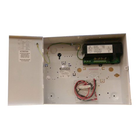
Elmdene EN3-34-U User manual

1
Technical Support: +44(0)23 9269 6638 (option 3) PAK200415 01C May 2016 ©2016 ELMDENE INTERNATIONAL LTD
EN3
-
34
-
U
13.8Vdc 3.0A with 2 x 17Ah Batteries
EN50131-6 Grade 3 P U
F
EATURE
Suitable for use in systems designed to comply with PD6662:2010 to Grade 3 and Environmental Class II. Rated to provide
continuous current to load for systems requiring 34Ah standby from two batteries. Each battery has its own independent
charger and monitoring circuits. Three independent output signals are provided for loss of mains fault (EPS), battery fault
(APS), and power supply fault (PSU). Comprehensive self-diagnostics can detect blown output and battery fuses, battery fail,
low battery voltage and low output voltage. The PSU incorporates intelligent battery management comprising active full
load battery testing, low battery voltage detection and deep discharge protection to ensure that the batteries are not
permanently damaged through excessive discharge. A brownout filter ensures that short mains voltage dips do not create a
false loss of mains alarm. Diagnostic LEDs assist with quick and easy installation by showing presence of mains, correct
individual battery charging or a fault condition. Comprehensive protection is built-in as standard including mains transient
filtering, transformer thermal fuse, electronic output overload protection and fuses on the load and battery outputs.
•EN50131-6:2008 Grade 3 Type A PSU
*
•EN50131-1 Environmental Class II
*
•Independent Intelligent Active Battery Monitoring on each battery
•Low quiescent battery monitoring current during standby operation
•Fault signals for loss of mains, battery fail and power supply fault
•Battery Deep Discharge Protection.
•Protection against reverse battery connection.
•Electronic overload protection shuts down output until overload or short circuit is removed (while on mains power).
•Transformer thermal fuse
•Mains transient suppression and brown-out filter
*
When installed in an enclosure that provides the required tamper arrangement and EMC shielding.
C
OMPLIANCE
*
This power supply unit complies with the following European Directives:
Low Voltage 2014/35/EU EMC 2014/30/EU WEEE 2012/19/EU
*
When installed in an enclosure that provides the required tamper arrangement and EMC shielding.
PECIFICATION
Input
Voltage 230Vac (+10% / -15%), 50Hz nominal
Current 640mA (Nominal at full load)
Mains input fuse T2.0A 20mm, 250Vac HRC
Output
Voltage 13.4 - 14.0 Vdc (Mains power 230Vac +10% / -15%)
9.6 – 13.0 Vdc (13.8 Vdc nominal) (Battery Standby)
Load Current (Continuous) 3A (Mains power)
2.8A
*
(with 2 x 17Ah batteries) (12 hours)
1.4A
*
(with 2 x 17Ah batteries) (24 hours)
Elmdene International Ltd
Tel: +44(0)23 9269 6638
3 Keel Close, Interchange Park, Fax: +44(0)23 9266 0483
Portsmouth, Hampshire, PO3 5QD, UK 
Web: www.elmdene.co.uk
2
Technical Support: +44(0)23 9269 6638 (option 3) PAK200415 01C May 2016 ©2016 ELMDENE INTERNATIONAL LTD
PECIFICATION
(
CONT
.)
Load output fuse F3.15A 20mm, 250Vac glass
Battery fuses (1 & 2) 2 x F3.15A 20mm, 250Vac glass
Ripple <100mV pk – pk @ 230Vac
<200mV pk – pk @ 230Vac -15%
Mechanical
Size (w x l x h) 170mm x 310mm x 80mm
Weight 2.8kg
Environmental
Temperature - operating -10 to +40
O
C 75% RH non-condensing
Temperature - storage -20 to +80
O
C
*
As calculated according to EN50131-6: 1997 Table 2.0 with maximum battery capacity fitted.
TAND
-B
Y
B
ATTERY
M
ANAGEMENT
Warning: risk of explosion if incorrect battery type fitted
Maximum Battery Size 2 x 17Ah 12V Valve Regulated Lead Acid (not supplied with unit)
Intelligent Battery Recharge Time < 24 hours to 80%
A heavily discharged battery having a terminal voltage > 5.0V will attempt to be
charged. If battery fails to accept charge in 24 hours it will fail the active load test.
Testing Battery Not Present: <5.5v battery voltage
Low battery voltage: <11.6v (no mains present)
Active load test at full rated output current
Protection Reverse battery connection protection
Deep Discharge Protection Both batteries disconnect when both have < 10.5v battery terminal voltage
Quiescent Current 100 mA when running on battery
< 100 μA after deep discharge protection.
IGNALLING
O
UTPUT
Rating 0.10A @ 60vdc 16Ω solid state relay contacts, voltfree.
EPS Fault Open if Loss of mains for >8s
APS Fault Open if for either battery:
Battery terminal voltage < 11.6v (with mains off), or
Active Battery Monitoring detects a failed battery
PSU Fault Open if Output voltage < 9.0v, or
Output short circuit, or
Output fuse blown
L
OCAL
D
IAGNO TIC
Green LED On = Mains Present
2 x Red LED’s (Bat1 & Bat2) Individual battery Diagnostics according to table:
Green LED (mains) Red LED (Bat1 & Bat2) tatus
ON OFF Normal. Battery fully charged
ON One short flash Normal. Battery charging
ON Two short flashes Fault. Battery self test (load test) fail.
ON Three short flashes Fault. No Battery or battery fuse failed)
ON Both Flashing: 1 second on 1 second off Fault. No Output (Fuse blown or short circuit)
OFF OFF Fault. No mains. No output. Batteries
disconnected or fully discharged
OFF One short flash Normal. tandby Mode. Battery present,
healthy and supplying load.
OFF Two short flashes Fault. Battery low voltage (<11.5v).
3
Technical Support: +44(0)23 9269 6638 (option 3) PAK200415 01C May 2016 ©2016 ELMDENE INTERNATIONAL LTD
C
ONNECTION
LOAD +, - Connection to equipment to be powered (Observe polarity)
BATT1 +, - Connection to standby battery 1. Use cables provided (Observe polarity)
BATT2 +, - Connection to standby battery 2. Use cables provided (Observe polarity)
APS FAULT Relay output for battery fail. Open if battery fail or open for low output.
EPS FAULT Relay output for mains fail. Open if loss of mains.
PSU FAULT Relay output for General Fault. Open in fault condition
I
N TALLATION
&
C
OMMI IONING
This unit is only suitable for installation as permanently connected equipment and must be used with DC appliances only.
The PSU is NOT SUITABLE for external installation. The PSU should be installed according to all relevant safety regulations
applicable to the application.
This unit must be fed from a mains power source having a separate (approved) disconnect device and fitted with a fuse or
other over-current protection device rated at 3A maximum. Ensure that the disconnect device used has appropriate earth
fault protection to the applicable standard.
Mounting
1) Mount securely into host enclosure allowing minimum clearance around chassis plate - see Fig. 1.0.
Mains Power Up
2) Attach correctly rated mains cable and fasten using cable ties.
3) Apply mains power. Check for 13.8v (nominal) on load outputs. Check green Mains LED is on.
4) Disconnect mains power.
Load Output
5) Attach correctly rated load cable(s) and fasten using cable ties and adhesive saddles.
6) Attach correctly rated fault signalling cable(s) and fasten using cable ties and adhesive saddles.
7) Attach supplied battery cables to terminal block and battery. NOTE: ensure correct polarity of battery connections:
+ve use red lead, -ve use black lead.
8) Apply mains power. Check green Mains LED is on.
9) Check there is no fault indication on the Red LEDs. A single short flash indicates that the corresponding battery is not
fully charged and is being charged. – This is OK.
10) Disconnect mains power. Check that the batteries continue to supply voltage and current to the load. NOTE: batteries
must have sufficient charge.
11) Reconnect mains.
Fig 1.0 Mounting the Power Supply
Mains input cable rating:
>3A, 300Vac minimum
Load output cable:
Current rating to match
Maximum load.
N E L
FUSED
SPUR
3A
MIN
MINIMUM
CLEARANCE WITH
WALLS OF HOST
ENCLOSURE
CHASSIS
ENCLOSURE
4
Technical Support: +44(0)23 9269 6638 (option 3) PAK200415 01C May 2016 ©2016 ELMDENE INTERNATIONAL LTD
O
PERATING
I
N TRUCTION
In the event of loss of mains, a battery fault or a PSU fault, the corresponding Fault signal contacts will open. If the output of
the PSU fails, the cause of the failure should be investigated e.g. short circuit load, connection of a deeply discharged
battery. The fault should be rectified before restoring power to the PSU. If any of the fuses require replacing, ensure the
correct fuse rating and type is used.
P
REVENTATIVE
M
AINTENANCE
This unit is intended for use by Service Personnel only. There are NO USER SERVICEABLE parts inside.
There is no regular maintenance required of the PSU other than periodic testing, calibration check and replacement of the
standby batteries. Reference should be made to the battery manufacturer's documentation to determine
typical/expected battery life with a view to periodic replacement of the battery
C
ALIBRATION
C
HECK
This power supply does not require calibration. If it is necessary to validate the calibration to comply with system inspection
requirements then use the following procedure.
1) Set a calibrated DVM on maximum resolution range to read 6.00 Vdc.
2) Connect meter to calibration pins marked J4.
3) Verify that the meter reading is within the range 5.00 – 5.50 Vdc.
If the unit fails its calibration check, it will continue to function but with reduced accuracy of detection of Low Battery
voltage and Low output voltage. Please contact the manufacturer for recalibration options.
INGLE
B
ATTERY
O
PERATION
The unit may be operated with only one battery. To avoid generating a fault condition connect +ve (red) battery lead to
Bat1+ and Bat2+, and connect the -ve (black) Battery lead to either Bat1- or Bat2-.
CAUTION
Dispose of used batteries according to the battery manufacturer’s
instructions and all local and national regulations

Other Elmdene Power Supply manuals

Elmdene 2401ST User manual

Elmdene

Elmdene 2401ST User manual

Elmdene STX2402 Series User manual

Elmdene

Elmdene STX2402 Series User manual

Elmdene 20182423N User manual

Elmdene

Elmdene 20182423N User manual

Elmdene G2410BMU User manual

Elmdene

Elmdene G2410BMU User manual

Elmdene 2402STE User manual

Elmdene

Elmdene 2402STE User manual

Elmdene G1380xBM Series User manual

Elmdene

Elmdene G1380xBM Series User manual

Elmdene STX2402-MOD User manual

Elmdene

Elmdene STX2402-MOD User manual

Elmdene 2405ST Series User manual

Elmdene

Elmdene 2405ST Series User manual

Elmdene STX2401-C User manual

Elmdene

Elmdene STX2401-C User manual

Elmdene TR2 User manual

Elmdene

Elmdene TR2 User manual

Elmdene G1380xN-y-s Series User manual

Elmdene

Elmdene G1380xN-y-s Series User manual

Elmdene STX2401-MOD User manual

Elmdene

Elmdene STX2401-MOD User manual

Elmdene GEN2-08 Series User manual

Elmdene

Elmdene GEN2-08 Series User manual

Elmdene 2405ST Series User manual

Elmdene

Elmdene 2405ST Series User manual

Elmdene G13804NU User manual

Elmdene

Elmdene G13804NU User manual

Elmdene G240 N Series User manual

Elmdene

Elmdene G240 N Series User manual

Elmdene GEN3-08-y User manual

Elmdene

Elmdene GEN3-08-y User manual

Elmdene VRS124000-P Series User manual

Elmdene

Elmdene VRS124000-P Series User manual

Elmdene G2410BM-E User manual

Elmdene

Elmdene G2410BM-E User manual

Elmdene POE1230-C User manual

Elmdene

Elmdene POE1230-C User manual

Elmdene G240 BM Series User manual

Elmdene

Elmdene G240 BM Series User manual

Elmdene 2401ST User manual

Elmdene

Elmdene 2401ST User manual

Elmdene STX2410-MOD User manual

Elmdene

Elmdene STX2410-MOD User manual

Elmdene STX2405-MOD User manual

Elmdene

Elmdene STX2405-MOD User manual

Popular Power Supply manuals by other brands

Bosch PSU-224-DC100 installation manual

Bosch

Bosch PSU-224-DC100 installation manual

S&C IntelliRupter PulseCloser P300 Installation

S&C

S&C IntelliRupter PulseCloser P300 Installation

Delta CliQ Installation

Delta

Delta CliQ Installation

nextys NPSM501-24 instruction manual

nextys

nextys NPSM501-24 instruction manual

Calira EVS 36/20-DS/IU operating instructions

Calira

Calira EVS 36/20-DS/IU operating instructions

Elkron AS500/RPT instruction manual

Elkron

Elkron AS500/RPT instruction manual

Alternative Heating & Supplies SUREFIRE 512 STOVE SENTRY instruction manual

Alternative Heating & Supplies

Alternative Heating & Supplies SUREFIRE 512 STOVE SENTRY instruction manual

Chord CPP1 user manual

Chord

Chord CPP1 user manual

MG MDC6 instruction manual

MG

MG MDC6 instruction manual

nextys NPSM481 Series instruction manual

nextys

nextys NPSM481 Series instruction manual

Siemens SITOP PSU100C 6EP1321-5BA00 operating instructions

Siemens

Siemens SITOP PSU100C 6EP1321-5BA00 operating instructions

Osram OPTOTRONIC OTe 18/220-240/500 PC manual

Osram

Osram OPTOTRONIC OTe 18/220-240/500 PC manual

Gibson Power Supply Schematic diagram

Gibson

Gibson Power Supply Schematic diagram

Altronix WPTV244UL Series installation guide

Altronix

Altronix WPTV244UL Series installation guide

phytron phyMOTION POWM01.1 manual

phytron

phytron phyMOTION POWM01.1 manual

Ametek Sorensen XDL Series II Operation manual

Ametek

Ametek Sorensen XDL Series II Operation manual

Ever POWERLINE 31 series instruction manual

Ever

Ever POWERLINE 31 series instruction manual

Sony CP-A2L Operating lnstructions

Sony

Sony CP-A2L Operating lnstructions

manuals.online logo
manuals.online logoBrands
  • About & Mission
  • Contact us
  • Privacy Policy
  • Terms and Conditions

Copyright 2025 Manuals.Online. All Rights Reserved.