ELME Servicebox 817 INNOVATION User manual

MANUAL
Servicebox 817
INNOVATION

Thank you for purchasing this
Servicebox to your 817 INN!
This guide provides the informaon needed to service and maintain
your spreader. A spreader used and serviced properly retain their
qualies for a long and protable life in service, and you get the full
advantage of all the features.
Maintenance may only be carried out by qualied personnel.
For more detailed informaon about spare parts and service
instrucons, we refer to our manual for the specic spreader.
All informaon, illustraons and specicaons in this manual are based on the latest informaon
at the me of publicaon. The right is reserved to make changes at any me without noce.
COPYRIGHT© 2021 ELME Spreader AB.

Index
Twistlock Assembly 4-9
Wear pads 10-13
Flextrack Chain Assembly 14-15
Summary of all parts included 16
Why use Genuine Parts? 17
The twistlock is a genuine ELME part, which is cered and marked with a unique
serial number.
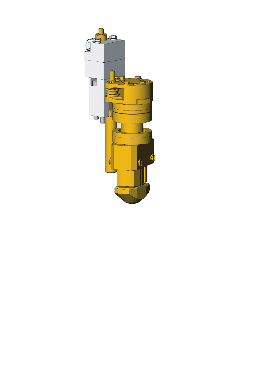
TWISTLOCK ASSEMBLY

To remove the tie-rod proceed as follows:
1 Remove the indicator assy. (item 14) or the Locked / Not locked sensor bracket
(item 1), if it is a spreader with WTP or with overheight legs.
2 Loosen one of the adjuster bolts at the twistlock cylinder, enough to give some play.
3 Loosen and remove the M8 x 80 bolts (item 2) in the top of both twistlocks in the
same end beam.*
4 Use two of the M8 x 80 bolts (item 2) as pullers by inserng them in the two th
readed holes (item 3) in each of the cranks (item 4) and ghten them alternatly
unl they li the cranks (item 4) o the top of the twistlock sha (item 5).
5 The e-rod (item 6) including both cranks (item 4) can now be removed from the
endbeam.*
To remove the twistlock and sleeve proceed as follows:
6 The key (item 7) that locates the crank (item 4) to the twistlock (item 5) is held in
place on the twistlock by a roll pin, so that it will remain in place on the twistlock
aer the crank is removed.
5
The e-rod is a xed unit and is not adjustable
(does not apply for WTP).

7 Support the twistlock (item 5) from below so that it does not drop out. Using a
screwdriver prise the collet (item 8) out of the recess in the twistlock (item 5). It is
now possible to lower the twistlock out of the end beam. The sleeve (item 9) and
lower bearing set (item 10) will in most cases accompany the twist lock as it is
removed, this is quite normal.
Inspection prior to reassembly
8 Aer removal of all twistlock parts, remove all grease and dirt from the parts and
also from the corner of the end beam. Steam clean or clean with some form of
solvent.
9 Heck the twistlock (item 5) for wear at the head and also for wear at the bushing
surfaces. Inspect the lower (item 10) and upper (item 11) bearing sets for wear
and damage, if badly worn or damaged, they should be replaced. The collets (item
8) and and the crank (item 4) should be inspected for possible wear or damage
and replaced if necessary.
It should be noted that the state of the collets (item 8) and the recess in the
twistlock (item 5) is very important as these parts are carrying the load when a
containerislied.
Replacing / Fitting twistlocks
10 Prepare the sleeve (item 9), place and grease the bushing and t the four cente-
ring springs in the sides of the sleeve.
11 Grease the upper bearing set (item 11) and place in posion on the greased top
surface of the corner plate (in the endbeam) with the convex half uppermost
(threaded holes up). Grease the lower bearing set (item 10) and place in posion
on the greased boom surface of the corner plate (in the endbeam, the grease
will hold it in place).
12 Li the sleeve assembly as assembled in point 10 and posion up through the
corner plate in the endbeam. Note the direcon of the grease nipple! Then place
the twistlock in the sleeve, ensuring that both bearings (item 10 and 11) are posi-
oned correctly around the twistlock. Support the assembly with a jack or other
means.
13 Fit the collets (item 8) with the pointed part upwards.
14 Fit the key (item 7) incl. roll pin to the keyway of the twistlock (item 5).
6

15 In order to t the e-rod (item 6) it is necessary to mount both cranks (item 4) to
the e-rod before placing it in the end beam.* Fit the ball joints, O-rings, and
plasc washers to the e-rod ends and then t the fork of the crank (item 4) over
the e-rod end. Ensure that the countersunk ends of the securing holes in the
crank are upper most. Secure the crank to the e-rod end by ng the pin (item
12) and then the ring pin and allen screw (item 13).
16 In order to simplify assembly of the crank to the twistlock it is advisable to t two
alignment pins to the assy. The pins can be made from two M8 x 75 bolts or allen
screws with the heads removed and slightly chamfered.
These pins should be screwed into the top plate of the upper bearing (item 11)
diagonally so that each pin guides one half of the collet (item 8).
17 Insert the e-rod (item 6) into the end beam and the t the cranks (item 4) onto
the alignment pins and ensure that the key and keyway line up. Fit two of the allen
securing (item 2) in the remaining two holes and screw in and ghten lightly. Re
move the alignment pins and t the other two securing screws. The securing
screws can now be ghtened to approx. 25 Nm.
18 Acvate the twistlocks to the NOT LOCKED posion and then adjust the twistlock
cylinder adjuster bolts, so that the twistlocks are posioned accurately in the NOT
LOCKED posion. Then adjust properly, see ”Twistlock angle adjustment”.
19 Grease the complete assembly with a high-pressure grease gun.
In order to test the operaon, it is necessary to land the spreader on a container
so that the seated pins are acvated.
* For spreaders with WTP (secon 3, 5 and 15 above), the removal/ng of bolts, e
rods and cranks can be done one by one.
7
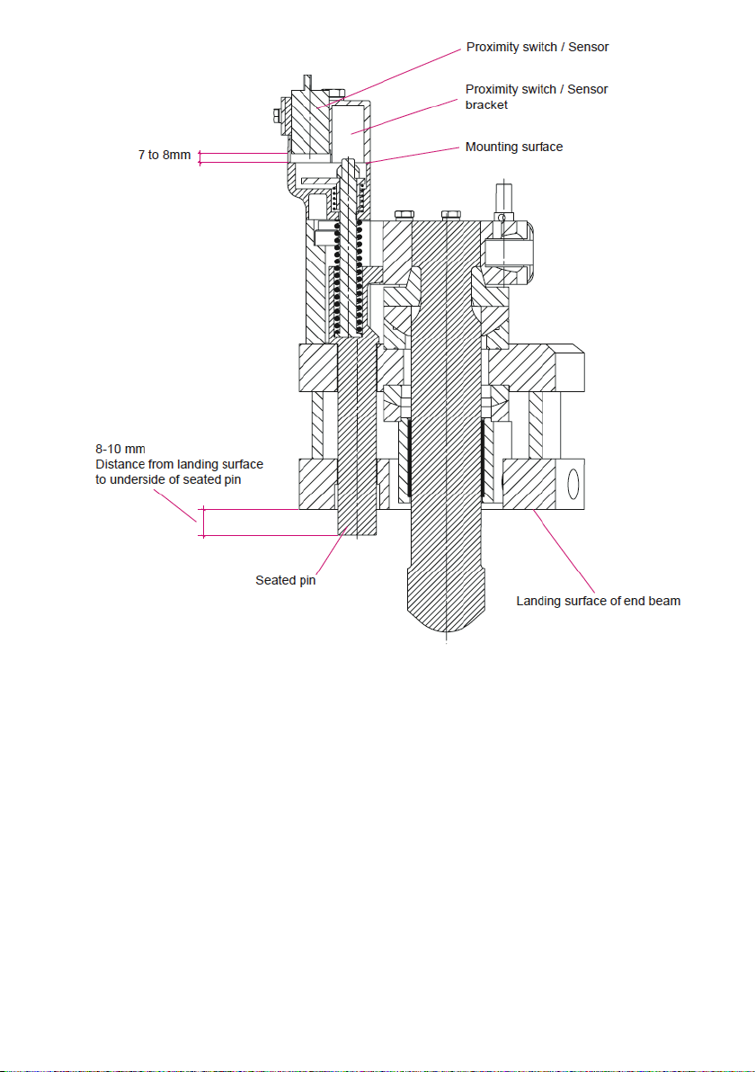
Seated / Landed signal adjustment
1 Check that the SEATED PIN can move up and down freely. The force needed to li
the pin is approx. 10 kg (20 lbs).
2 The SEATED signal should switch on with the pin protruding approx. 9 mm below
the landing surface of the end beam.
3 If adjustment of the proximity switch / sensor is necessary, remove the seated
sensor mounng bracket incl. sensor from the top of the seated tower, and adjust
the proximity switch / sensor so that the end surface is 7-8 mm above the lower
mounng surface of the bracket. This adjustment will result in the seated pin
indicaon being switched on when the underside of the seated pin is approx. 8 to
10 mm lower than the end beams landing surface. This adjustment also ensures
that the mechanical and electrical lockout is released so that the twistlocks can
be turned.
8

9
1 Turn the twistlocks (pos 1) to the fully UNLOCKED posion (as shown).
2 If the twistlock heads do not line up with the twistlock sleeve, they can be
adjusted by loosening the lock nuts (pos 5) for the adjuster bolts (pos 2).
3 Turn the twistlocks at each end of the end beam so that they line up with the
sleeves, if it is found dicult to line up the twistlocks and sleeves accurately distri-
bute the misalignment equally on both sides of the sleeve. Make sure that the
twistlock heads DO NOT protrude outside the theorecal line between the twist-
locks. If the twistlocks do protrude outside the previously menoned line bet
ween the twistlocks it can cause jamming in corner casngs as the spreader is
lied o the container.
4 Run both adjuster bolts (pos 2) up to the piston rod (pos 4) ends of the twistlock
cylinder (pos 3) by hand, making sure that neither the twistlocks nor the cylinder
are moved. Tighten the lock nut (pos 5a) of the inside adjuster (pos 2a) rst.
5 Unscrew / back o the outer adjuster bolt (pos 2b) no more than 2 ats of the
hexagan head (60°) so that there is only just enough play to allow the e rod (pos
6) to slide back and forth across the adjuster bolts when the twistlock cylinder
(pos 3) is acvated. CAUTION if the gap between the twistlock cylinder rod ends is
too large the rod ends will hammer against the adjusters and subsequent damage
will occur to the piston rod ends.
6 Tighten the lock nut (pos 5b) securely while at the same me ensuring that the
adjuster bolt (pos 2b) does not move.
7 Acvate the twistlocks to the LOCKED posion and check that the twistlock heads
are 900+/- 100 to the twistlock sleeve.
Twistlock angle adjustment
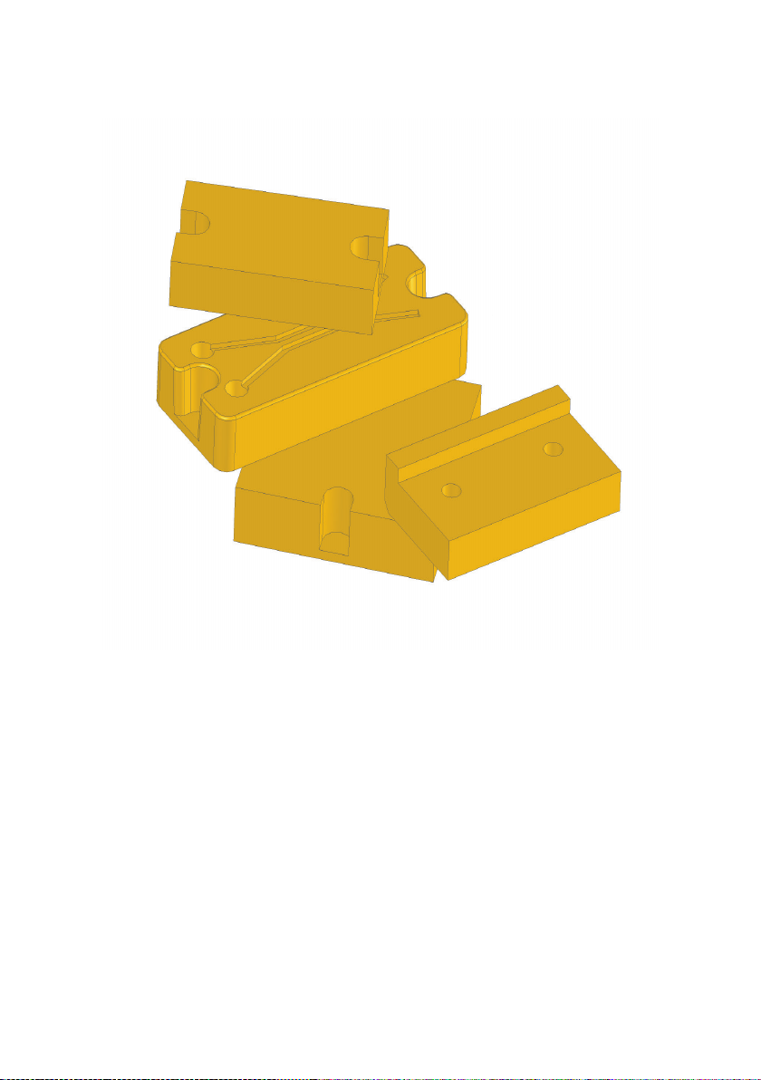
To eliminate mechanical fricon, there are plasc pads between extension beams and
main frame. The pads are posioned for support to reduce and also to absorb horizon-
tal and vercal shock loads, they are mounted in several retainers. This design makes
inspecon and replacement easy.
WEAR PADS

11
Wear pads wear limits
Below pictures and tables show the maximum wear limits for the dierent wear
pads on the spreader. Make sure to regularly inspect the wear pads and to
replace them when needed.
The nylon wear pads should be inspected for wear at the same me as their
tracks are lubricated. Replacing the wear pads can be done with ordinary hand
tools and without removing the beams.
12
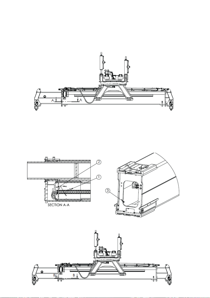
Changing wear pads
1. Extend the le extension beam ~1000 mm to make room for service on the right
beam. If the spreader has the opon hydraulic stops, disassemble the stop cylinder.
2. Use a M6S 20x90 bolt (1) to li the rear end of the extension beam ~2 mm to
make sure the extension beam does not rest on the lower wear pad. There should
be a gap le between the upper wear pads and the main frame.
Loosen the 4 bolts (2). In order to replace the side wear pads, remove the inner
bolts (3), on each side.
3. Extend the right extension beam ~400 mm. The beam will slide on (1).

13
Changing wear pads
4. Now it is possible to remove the upper wear pads by loosening bolts (4) and pull
out the wear pad retainer. *
Remove the side wear pad bolts (5) and pull out the wear pad retainer. *
5. Remove the lower wear pads (6) by pulling the retainer (7) to the posion shown
inn the below gure.*
Finish the service by retracng the extension beam and remove the M6S 20x90
bolt (1). Tighten all bolts to recommended ghtening torque, according to manual.
Reassemble the stop cylinder, if you have the opon hydraulic stop.
6. Repeat the procedure for the opposite extension beam.
*Change wear pads and reassemble in reverse order.

Included in this service box is a complete assembly of extrack chain, hydraulic hoses
and electrical cable. On the following pages, you will nd instrucons how to replace
the extrack chain assembly.
FLEXTRACK CHAIN ASSEMBLY
15
4
5
2
3
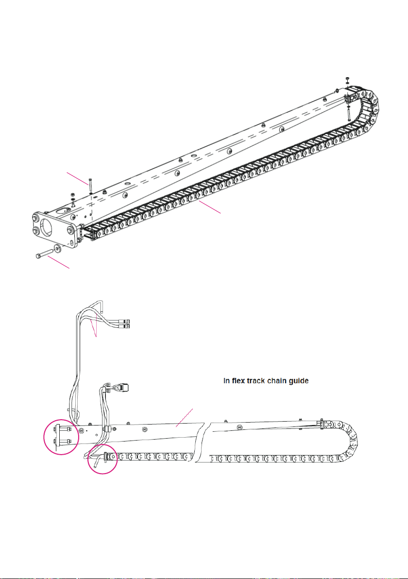
Flex track chain guide
1 Cable chain
2 Bolt
3 Bolt
4 Hydraulic hose assy.
5 Flex track chain guide
To change ex track chain, loosen and remove the circled bolts, replace the ex
track chain and reassamble in reverse order.
1

16
Summary of all parts included in the box:
Twistlock Assembly 4x Twistlock kit
4x Seated pin
4x Nut
4x Bracket
4x Indicator arm
4x Tie rod
4x Compression spring
4x Compression spring
Wear pads 12x Wear pad - Mainframe
4x Wear pad - Mainframe lower
4x Wear pad - Extension beam lower
4x Wear pad - Extension beam upper
2x Wear pad - Extension beam lower
2x Wear pad - Extension beam lower
4x Wear pad - Rotator
4x Wear pad - Rotator
4x Shims - Rotator
4x Shims - Rotator
Flextrack Chain Assembly 2x Flex track chain
4x Hydraulic hose assy.
2x Cable assy.
2x Cable assy. (work lights)

ELME GENUINE PARTS
By using ELME genuine parts, you always get parts you can rely on and true peace of
mind. If you are using non-genuine parts, you put weak links into a strong, perfectly
designed chain of interacve components. Please note that non-genuine parts are made
by factories that have not been approved by ELME and they are oen manufactured to be
as cheap as possible, using inferior materials, workmanship and by reversed engineering.
Non-genuine parts are high risk. Real cost and real risk is measured not in the price, but in
the cost of the component in the event of failure. Use of non-genuine parts may lead to
higher downme and lower producvity due to more frequent failures. For correct operaon
of the spreader, only ELME Genuine Parts and accessories which are approved by ELME should
be used. If non-genuine parts are used, the warranty is not valid. By using ELME Genuine Parts
and accessories approved by ELME, you will maintain original standard. ELME will disclaim all
responsibility if parts from third party are used.
INSPECTION/MAINTENANCE
Always inspect your spreader before using it. If any kind of damage is detected – which may af-
fect the funcon of the spreader - this must be corrected before use. If the spreader needs to be
repaired, please contact a specialist and see to that only ELME Genuine Parts are used if need of
replacement. This is to ensure that the spreader sll is reliable. Repairs made by a non-qualied
person or use of non-genuine parts may lead to increased risk of personal injuries or damages.
Service and maintenance are necessary to keep capacity and eciency of the spreader for many
years.
MODIFICATION OF THE SPREADER/PRODUCT LIABILITY/WARRANTY
For the avoidance of doubt, ELME is not liable in case of damage due to factors beyond ELME’s
control or due to a lack of maintenance or the use of non-genuine parts. The spreader should
not be modied without consultaon with ELME. If so, this means that the spreader is not CE
approved and thus ELME has no product liability.
Why use Genuine Parts?
17

HEADOFFICE
ELME Spreader AB
Älmhult, Sweden
www.elme.com
SALES AND SPARE PARTS
ELME Spreader Trading (Shanghai) Co. Ltd
Shanghai, China
SPARE PARTS
ELME Americas Inc.
Marn, TN, United States
© ELME Spreader AB • 2021 Servicebok 817 INNOVATION Manual
Other ELME Service Equipment manuals


