ElMod M16 v.2.0 Assembly instructions

!ElMod M16 v.2.0
Installation guide and user manual
Read these instructions carefully before installation! Any liability for damage caused
by improper installation or non-observance of these instructions is excluded."
Scope of delivery
•ElMod M16 board"
•2-pin cable for optional front lighting connection"
•USB dongle with matching USB cable for connection to a Windows®or Apple®
computer"
Overview of connections
1
Power terminal
9
Connector for main motor
2
Power switch
10
Connector for turret components
3
Front light connector (optional)
11
Volume control knob
4
Rear light/brake light connector
12
microSD card
5
Connector for USB dongle
13
Wires for loudspeaker
6
Connector for steering servo
7
Connector for muzzle flash
L1
Status LED (Driving functions)
8
Wires for receiver connection
L2
Status LED (Sound functions)
Page 1

Installation and connection
The board has been designed to be installed with a minimum of soldering work. The
connectors used correspond to those of the original electronics."
•Remove the original board. Be careful not to damage the sensitive connectors. "
•Place the ElMod board in the place of the original electronics and fix it with two
screws at the designated places. "
•Connect the cables for the power supply, the main motor and the steering servo to
the appropriate connectors 1, 6 and 9 (see section "Overview of connections"). $
Page 2

$
CAUTION! It is possible that the manufacturer of the vehicle may change the wiring
without notice! Make sure that the polarity of the cables for the power supply is
correct. The polarity of connector 1 (power supply) on the circuit board is clearly
marked with + and -.$
CAUTION! The ElMod M16 board features a battery protection which should be set
accordingly to the used battery type. See chapter "battery protection" for details."
•Connect the rear light to connector 4. Option: the front light is attached directly to
the drive motor in the model and lights up as soon as the vehicle moves forward. If
the supply lines for the front lighting are separated from the main motor, they can be
attached to connector 3 with the supplied 2-wires cable. This allows the front light
to be switched on and offvia the remote control. In addition, the brightness can be
changed via the ElMod App."
Page 3

•Connect a suitable 4-channel receiver to the receiver cables. The assignment of the
cables is as follows: "
•Connect the speaker (required impedance 8 Ohm) to the orange wires."
Page 4
Wire color
Channel
Control
Function
1
Right stick
Acceleration/Braking
2
Steering
3
Left stick
Gun elevation, shot function and motor ignition
4
Turret rotation
BEC
Power supply of the receiver

•Connect the 8-pin tower plug to connector 10 and the 2-pin muzzle flash plug to
connector 7. The muzzle flash plug can be aligned in any way as both contacts on
the circuit board are connected together. $
ATTENTION! The plugs are very fragile! The thin wires can easily be torn offor the
connector housings may be damaged."
•Make sure that the vehicle cannot drive away by jacking it up or pulling offthe
chains."
•Insert full charged batteries. Switch on the receiver first and then the electronics.
Both LEDs (L1 and L2) light up after a short time. If this is not the case, check all
connections and the power supply. The cause of the malfunction can be localized
using the light patterns."
•Push the left lever of your remote control all the way up to ignite the engine. If no
function or another function has been triggered, the channel assignment is incorrect
or your radio system has activated the servo reversal function. For the correct
function, all possibly set mixers must be deactivated."
•If you do not hear any sound, check that the volume control is set too low."
•The model is now ready for use."
Page 5
L1 (status of
drive
functions)
off
No voltage (check switch and battery
fast blinking
No receiver signal detected
Quick blinking
every 2 sec.
Battery discharged (L1 blinks together with the
lighting and the muzzle flash. Driving is disabled)
on
Operational
L2 (status of
Sound
functions)
off
No SD card created or damaged SD card
blinking
A possible hardware fault
on
Operational

Control and functions
!The engine is operated with the right stick of the RC radio. In the vertical axis
the drive motor is accelerated and braked, in the horizontal axis the steering servo is
controlled. The receiver signal for the servo is transmitted directly to the servo without
further processing. The acceleration information is processed in the electronics and
extended by mass inertia simulation. "
!In order for the vehicle to be moved, the engine must first be "ignited". This is
done with the left stick (briefly bring the lever down to full deflection). The acceleration
and braking power corresponds to the deflection of the right stick. During braking, the
rear light is brighter simulating a brake light."
!The left stick controls the AA gun turret and special functions. The function
assignment can be taken from the table below."
Configuration
!The ElMod M16 is already factory set for the model. With the help of the free
ElMod App it is however possible to adapt the electronics exactly to your needs. The
software is freely available for Microsoft®Windows®operating systems and MacOS®.
This can be used, for example, to set various driving parameters or the brightness of
the lighting."
!Please note that during the installation of the software it may be necessary to
ensure that virus protection software or other security settings do not prevent access
to the USB hardware or block the execution of the program. "
!Under Microsoft®Windows® it is necessary to install a driver for the USB
dongle. This driver is included in the installation package. Alternatively, the driver can
be downloaded directly from the manufacturer. The link can be found on our website.$
!Under MacOS®the driver is already integrated in the system. If you did not
download the ElMod App in the App Store®, it may be necessary to explicitly allow
the execution of the ElMod App. To do this, start "Security & Privacy" in the System
Preferences, then click on "Allow apps downloaded from: App Store and identified
developers". After the first execution of the ElMod App, return to the "Security &
Privacy" settings and click on "allow" right to the listed ElMod App. This only needs to
be done once."
Page 6
↔
Full deflection
Turret rotation
↘
Quick
movement
User sound 1
↕
Up to 2/3
deflection
Gun elevation
↗
Quick
movement
Light on/off
⬆
Full deflection
AA gun on/off
↖
Quick
movement
User sound 2
⬇
Full deflection
Engine on/off
↙
Quick
movement
User sound 3

!To connect your computer to the ElMod M16 attach the USB dongle to a free
USB plug in your computer. The dongle is connected to connector 5 of the ElMod
M16. Now switch on the ElMod M16 and start the ElMod App on your computer.
After a couple of seconds the ElMod M16 will be found and the current settings will
be transferred. "
The user interface of the ElMod App is divided into the following areas:"
•at the top there is a tab with which the available parameter categories."
•The parameters of the selected category are located in the central area. Each
parameter has a detailed description. This is displayed when you move the mouse
pointer over the parameter name and wait briefly. "
•below there are five buttons:"
•"Load profile" loads a previously saved profile or one supplied with the
configuration program from your hard disk. The values of all parameters are stored
in the setting profile. This allows you to quickly and easily switch between different
settings (e.g. for two different models)."
•"Save profile" saves all current settings on your hard disk."
•"Help" shows compact instructions for operating the configuration program."
•"Info" shows the version number of the program and legal information."
•"Exit" closes the program."
Battery protection
The ElMod M16 is equipped with a voltage monitor which protects the battery from
deep discharge. The setting of the battery type can be changed in the ElMod App.
The standard setting is 6-cell NiMH battery. With this setting any other battery type
can be used, but in this case no protection is given."
In order for the battery protection to become active, the switch-offvoltage must be
undercut for at least one second. All driving functions and sound are then disabled.
The lighting and the muzzle flash light up briefly every 2 seconds to signalise the
undervoltage state. To switch offthe active battery protection again, the electronics
must be switched offand on again."
Safety instructions
General
- Damage caused by non-observance of these operating instructions will void the warranty! We assume no liability for consequential
damages!"
- We accept no liability for damage to property or personal injury caused by improper handling or non-compliance with the safety
instructions! In such cases all warranty claims are void."
- For safety and approval reasons (CE), unauthorized modification or conversion of the device is not permitted. Only use original spare
parts or equivalent spare parts for repairs."
- Make sure that all electrical connections and connections have been made correctly and in accordance with these operating
instructions."
- If the ambient climate changes suddenly (e.g. from a cold room to a warm room), moisture can condense on the unit and possibly
destroy it. Do not operate the unit until it has been acclimatized for about 2 hours."
- Do not operate the device in the vicinity of easily inflammable objects, liquids or gases, danger of explosion!"
- Do not expose the device to high temperatures, strong vibrations, high humidity or chemically aggressive environments."
- Operate the device only in a dry environment (below 80 % humidity, non-condensing) and at normal room temperature."
- Do not operate the unit unattended."
Page 7

- If you have any questions about the operation, safety or connection of the device that are not explained in the operating instructions,
please contact your dealer's support or another specialist."
Electrical hazards
- Supply the device only with low voltage as specified in the technical data. Only use current sources approved for model making,
such as NiMh rechargeable batteries. Operation with voltages higher than 12V is not permitted. There is a fire hazard!"
- Observe the limit values for currents as specified in the technical data. Exceeding the permissible values leads to overloading and
destruction of the device and carries the risk of fire or electric shock."
- Installation and connection must only be carried out when the device is disconnected from the power supply."
- Ensure that all connecting cables have a sufficient cross-section."
Heat hazards
- Electronic components on the product can become very hot during operation."
- During installation, ensure that there is sufficient air circulation around the device to prevent overheating due to heat accumulation."
- During installation, also ensure that there is sufficient distance to heat-sensitive and flammable objects (e.g. wooden and plastic
surfaces, cable insulation)."
- Touching the device may burn the skin."
Other hazards
Children can cause all the risks described above due to carelessness or a lack of sense of responsibility. To avoid danger to life and
limb, children under the age of 14 must not install our products. Small children can swallow or inhale the sometimes very small
components with pointed ends. Danger to life! Therefore, do not allow the components to fall into the hands of small children. In
schools, educational institutions, hobby and self-help workshops, the assembly, installation and operation of components must be
supervised by trained personnel. In industrial facilities, the accident prevention regulations of the Association of Industrial Employers'
Liability Insurance Associations for electrical systems and equipment must be observed."
DECLARATION OF CONFORMITY
The product meets the requirements of EC Directive 89/336/EEC on Electromagnetic Compatibility and bears the CE marking for this
purpose."
MANUFACTURER'S NOTE
According to DIN VDE 0869, the person who makes an assembly ready for operation by extension or housing installation is regarded
as the manufacturer and is obliged to supply all accompanying documents when passing on the product and also to state his name
and address."
WARRANTY CONDITIONS
!This product is guaranteed for 2 years. The guarantee covers the free remedy of defects which can be proven to be
attributable to material used by us which is not faultless or to manufacturing faults. We guarantee that the components will function in
accordance with their characteristic values when unassembled and that the technical data of the circuit will be complied with when
installed in accordance with the instructions and with the prescribed commissioning and operating instructions. Further claims are
excluded. We assume no liability beyond the legal regulations of German law for damages or consequential damages in connection
with this product. We reserve the right to repair, repair, replace or refund the purchase price."
!In the following cases the warranty claim expires: In case of damage due to non-observance of the instructions and the
connection diagram, in case of modification and repair attempts of the circuit, in case of unauthorized modification of the circuit, in
case of improper removal of components not provided for in the construction, free wiring of components such as switches,
potentiometers, sockets etc., in the event of destruction of conductor tracks and solder lugs, incorrect assembly or incorrect polarity
of the module / components and the resulting consequential damage, damage due to overloading of the module, connection to an
incorrect voltage or type of current, damage due to intervention by third parties, persons, incorrect operation or damage due to
negligent treatment or misuse, damage due to contact with components before electrostatic discharge of the hands."
Nicht geeignet für Kinder unter 14 Jahren.
Not suitable for Children under 14 years.
Ne convient pas pour des enfants de moins de 14 ans.
Niet geschikt voor kinderen onder de 14 jaar.
ElMod Thomas Kusch
Seebuckweg 9
D-78054 Villingen-Schwenningen, Germany
ElMod Thomas Kusch
Page 8
Table of contents
Other ElMod Control Unit manuals

ElMod
ElMod Fusion ECO Operating and maintenance manual
ElMod
ElMod ThinkTank Tank Module PRO II Flex Assembly instructions
ElMod
ElMod ThinkTank Blaster 2 Installation instructions
ElMod
ElMod Famo Assembly instructions
ElMod
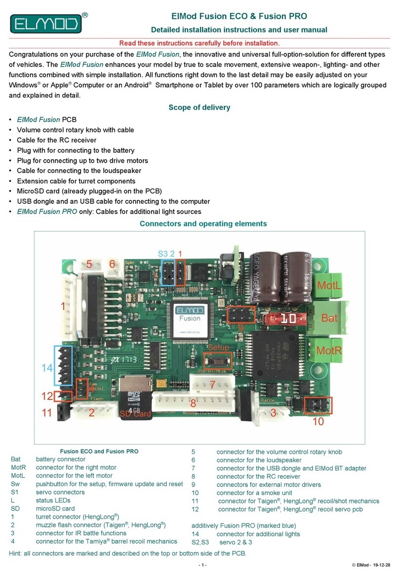
ElMod Fusion ECO Operating and maintenance manual
ElMod
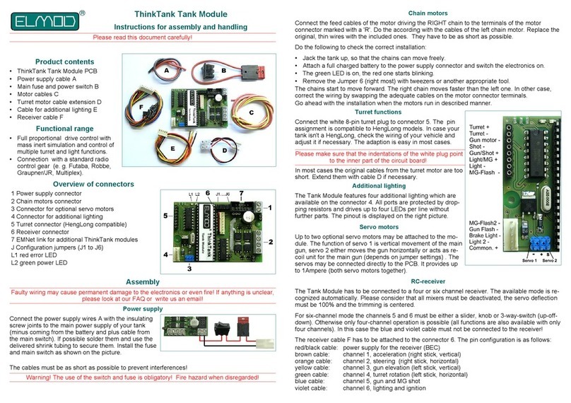
ElMod ThinkTank Tank Module Assembly instructions
ElMod
ElMod ThinkTank Pro Assembly instructions
ElMod
ElMod ThinkTank Tank Module ECO Flex Assembly instructions

ElMod
ElMod ThinkTank Tank Module ECO Assembly instructions
ElMod
ElMod ThinkTank Tank Module PRO II Assembly instructions
