manuals.online logo
Brands
  1. Home
  2. •
  3. Brands
  4. •
  5. ElMod
  6. •
  7. Control Unit
  8. •
  9. ElMod ThinkTank Tank Module Assembly instructions

ElMod ThinkTank Tank Module Assembly instructions

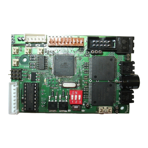
ThinkTank Tank Module
Instructions for assembly and handling
Please read this document carefully!
Product contents
•ThinkTank Tank Module PCB
•Power supply cable A
•Main fuse and power switch B
•Motor cables C
•Turret motor cable extension D
•Cable for additional lighting
•Receiver cable F
Functional range
•Full proportional drive control with
mass inert simulation and control of
multiple turret and light functions.
•Connection with a standard radio
control gear (e. g. Futaba, Robbe,
Graupner/JR, Multiplex).
Overview of connectors
1 Power supply connector
2 Chain motors connector
3 Connector for optional servo motors
4 Connector for additional lighting
5 Turret connector (HengLong compatible)
6 Receiver connector
7 MNet link for additional ThinkTank modules
J Configuration jumpers (J1 to J6)
L1 red error L D
L2 green power L D
Assembly
Faulty wiring may cause permanent damage to the electronics or even fire! If anything is unclear,
please look at our FAQ or write us an email!
Power supply
Connect the power supply wires A with the insulating
screw joints to the main power supply of your tank
(minus coming from the battery and plus cable from
the main switch). If possible solder them and use the
delivered shrink tubing to secure them. Install the fuse
and main switch as shown on the picture.
The cables must be as short as possible to prevent interferences!
Warning! The use of the switch and fuse is obligatory! Fire hazard when disregarded!
Chain motors
Connect the feed cables of the motor driving the RIGHT chain to the terminals of the motor
connector marked with a 'R'. Do the according with the cables of the left chain motor. Replace the
original, thin wires with the included ones. They have to be as short as possible.
Do the following to check the correct installation:
•Jack the tank up, so that the chains can move freely.
•Attach a full charged battery to the power supply connector and switch the electronics on.
•The green L D is on, the red one starts blinking.
•Remove the Jumper 6 (right most) with tweezers or another appropriate tool.
The chains start to move forward. The right chain moves faster than the left one. In other case,
correct the wiring by swapping the adequate cables on the motor connector terminals.
Go ahead with the installation when the motors run in described manner.
Turret functions
Connect the white 8-pin turret plug to connector 5. The pin
assignment is compatible to HengLong models. In case your
tank isn't a HengLong, check the wiring of your vehicle and
adjust it if necessary. The adaption is easy in most cases.
Please make sure that the indentations of the white plug point
to the inner part of the circuit board!
In most cases the original cables from the turret motor are too
short. xtend them with cable D if necessary.
Additional lighting
The Tank Module features four additional lighting which are
available on the connector 4. All ports are protected by drop-
ping resistors and drives up to four L Ds per line without
further parts. The pinout is displayed on the right picture.
ervo motors
Up to two optional servo motors may be attached to the mo-
dule. The function of servo 1 is vertical movement of the main
gun, servo 2 either moves the gun horizontally or acts as re-
coil unit for the main gun (depends on jumper settings) . The
servos may be connected directly to the PCB. It provides up
to 1Ampere (both servo motors together).
RC-receiver
The Tank Module has to be connected to a four or six channel receiver. The available mode is re-
cognized automatically. Please consider that all mixers must be deactivated, the servo deflection
must be 100% and the trimming is centered.
For six-channel mode the channels 5 and 6 must be either a slider, knob or 3-way-switch (up-off-
down). Otherwise only four-channel operation is possible (all functions are also available with only
four channels). In this case the blue and violet cable must not be connected to the receiver!
The receiver cable F has to be attached to the connector 6. The pin configuration is as follows:
red/black cable: power supply for the receiver (B C)
brown cable: channel 1, acceleration (right stick, vertical)
orange cable: channel 2, steering (right stick, horizontal)
yellow cable: channel 3, gun elevation (left stick, vertical)
green cable: channel 4, turret rotation (left stick, horizontal)
blue cable: channel 5, gun and MG shot
violet cable: channel 6, lighting and ignition
Connect the B C-cable and the channel lines 1 to 4 (or 1 to 6 for six-channel operation) to your
receiver. The plugs fit for most brands of receivers but they are not protected against polarity re-
versal. Check the manual for the information which pin carries the servo signal. If the plugs are
connected amissly, the receiver won't work.
Depending on the receiver it may be necessary to adjust the channel order or swap its movement
direction. Check the manual of your radio for details.
Jumper settings
The tank model is determined by the jumpers 1 to 3 (on - jumper set, off - jumper removed):
J1 J2 J3 Description
on on on User defined (only when ThinkTank Configurator is
used)
off on on German, WW2, plastic gearbox
on off on German, WW2, metal gearbox
off off on German, WW2, 3:1 reduction gearbox
on on off US, WW2 , plastic gearbox
off on off US, WW2, metal gearbox
on off off T-34
off off off Fun tank
Jumper 4 has no function yet and is reserved for future use.
Jumper 5 and 6 determine the used type of barrel recoil mechanics. Please consult our website
for detailed information about the wiring.
J5 J6 Description
on on No recoil mechanics
off on Tamiya compatible recoil mechanics
on off WSN-T34 recoil mechanics
off off Use of servo motor 2 for barrel recoil
Operation state LEDs
A red and a green L D display the current operational state of the Tank Module
Power-L D (green) on Module is operational
short blinking Stick movement detected
rror-L D (red) blinks No valid signal from receiver*
* no connection to the sender or the transmission path between sender and receiver is disturbed.
Please check the wiring and the proper function of the RC radio and receiver. If necessary check
the operability of the RC equipment with a servo.
If additional ThinkTank modules are attached via MNet-Link and the power-L D blinks per-
manently with the error-L D, the data transfer between the modules is disturbed. In this case
please contact our support for assistance.
First run
•Make sure that all connections are well fixed and that no conductive parts can touch each
other.
•Switch on the remote control and the tank in this order.
•The green power-L D lights, the red error-L D blinks 1-2 (searching for a valid receiver signal)
times and stays off.
•Move the left or right stick a little and watch the power-L D. It blinks once every time the sticks
are moved out of their neutral position. The electronics is operable now.
Normally, no parts should generate excessive heat. If you notice any abnormal overheating imme-
diately switch off the power and check the following list:
•is the wiring correct and no short circuits is detectable?
•is the gearbox smooth-running?
•Are the motors properly surpressed (two capacitors between each motor terminal and the
motor housing and a third capacitor between the motor terminals)?
Brakes
The Tank Module features several braking modes:
Motor brake Chain brake Emergency brake
Put the lever in neutral position.
Rolling out
move the stick to opposite
direction
full proportional brake
move the stick completely to
opposite direction
Immediate halt
Turret functions, 4-channel operation
The control of the light group and the tower unit is carried out as follows (left stick):
èRotate turret right éShot (maximum deflection)
çRotate turret left êMachine gun (maximum deflection)
éLift cannon (half deflection) Main light (“Light” on connector 5)
êLift cannon in opposite direction (half deflection) Auxiliary light (“Light 2” on connector 4)
ngine on/off (function requires a ThinkTank
Blaster module)
Turret functions, 6-channel operation
The control of the light group and the tower unit is carried out as follows:
Left stick Channel 5 Channel 6
èRotate turret right éShot éngine on/off (with TT Blaster)
çRotate turret left êMachine gun êMain light (full deflection)
éLift cannon êAux light (half deflection)
êLift cannon in opposite direction
Please visit our website and take a look on the FAQ for in-depth information
Nicht geeignet für Kinder unter 14 Jahren.
Not suitable for Children under 14 years.
Ne convient pas pour des enfants de moins de 14 ans.
Niet geschikt voor kinderen onder de 14 jaar.
lMod Dipl.-Inf.(FH) Thomas Kusch und Jürgen K. Huber GbR
Millotstraße 15/1
D-72622 Nürtingen
ElMod Dipl.-Inf.(FH) Th. Kusch & Jürgen K. Huber GbR
info@el-mod.de http://www.el-mod.de

Other ElMod Control Unit manuals

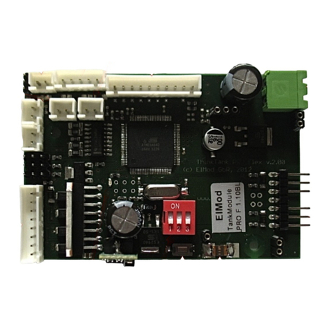
ElMod ThinkTank Pro Assembly instructions

ElMod

ElMod ThinkTank Pro Assembly instructions

ElMod ThinkTank Tank Module ECO Assembly instructions

ElMod

ElMod ThinkTank Tank Module ECO Assembly instructions

ElMod Fusion ECO Operating and maintenance manual

ElMod

ElMod Fusion ECO Operating and maintenance manual

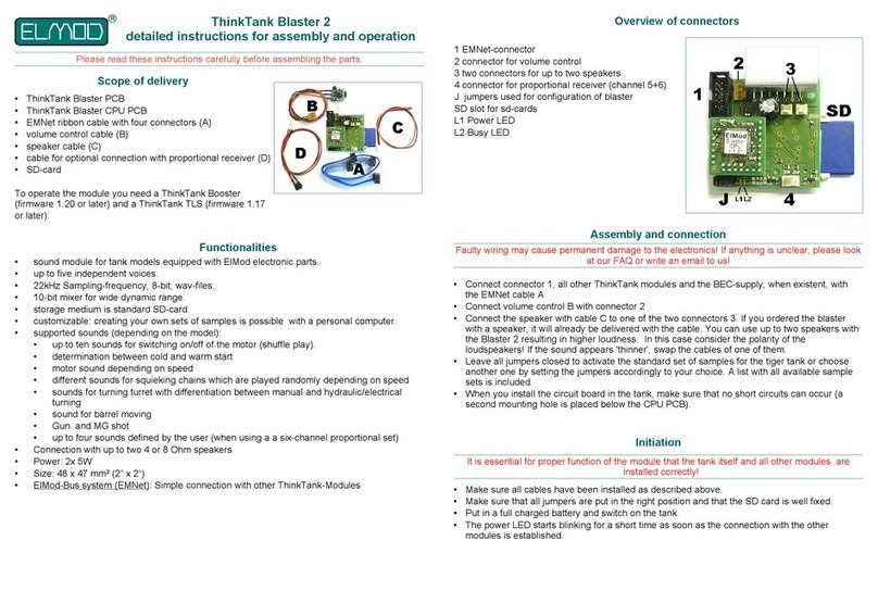
ElMod ThinkTank Blaster 2 Installation instructions

ElMod

ElMod ThinkTank Blaster 2 Installation instructions

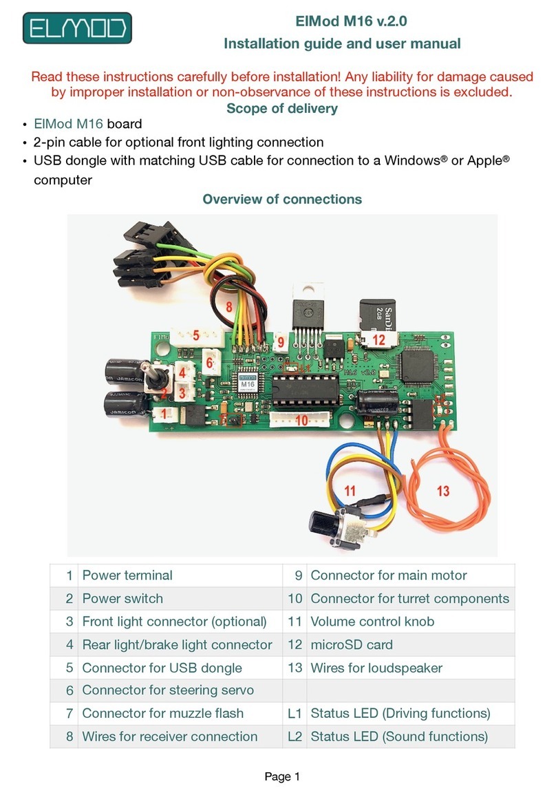
ElMod M16 v.2.0 Assembly instructions

ElMod

ElMod M16 v.2.0 Assembly instructions

ElMod Fusion ECO Operating and maintenance manual

ElMod

ElMod Fusion ECO Operating and maintenance manual

ElMod ThinkTank Tank Module ECO Flex Assembly instructions

ElMod

ElMod ThinkTank Tank Module ECO Flex Assembly instructions

ElMod ThinkTank Tank Module PRO II Flex Assembly instructions

ElMod

ElMod ThinkTank Tank Module PRO II Flex Assembly instructions

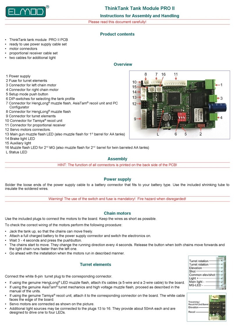
ElMod ThinkTank Tank Module PRO II Assembly instructions

ElMod

ElMod ThinkTank Tank Module PRO II Assembly instructions

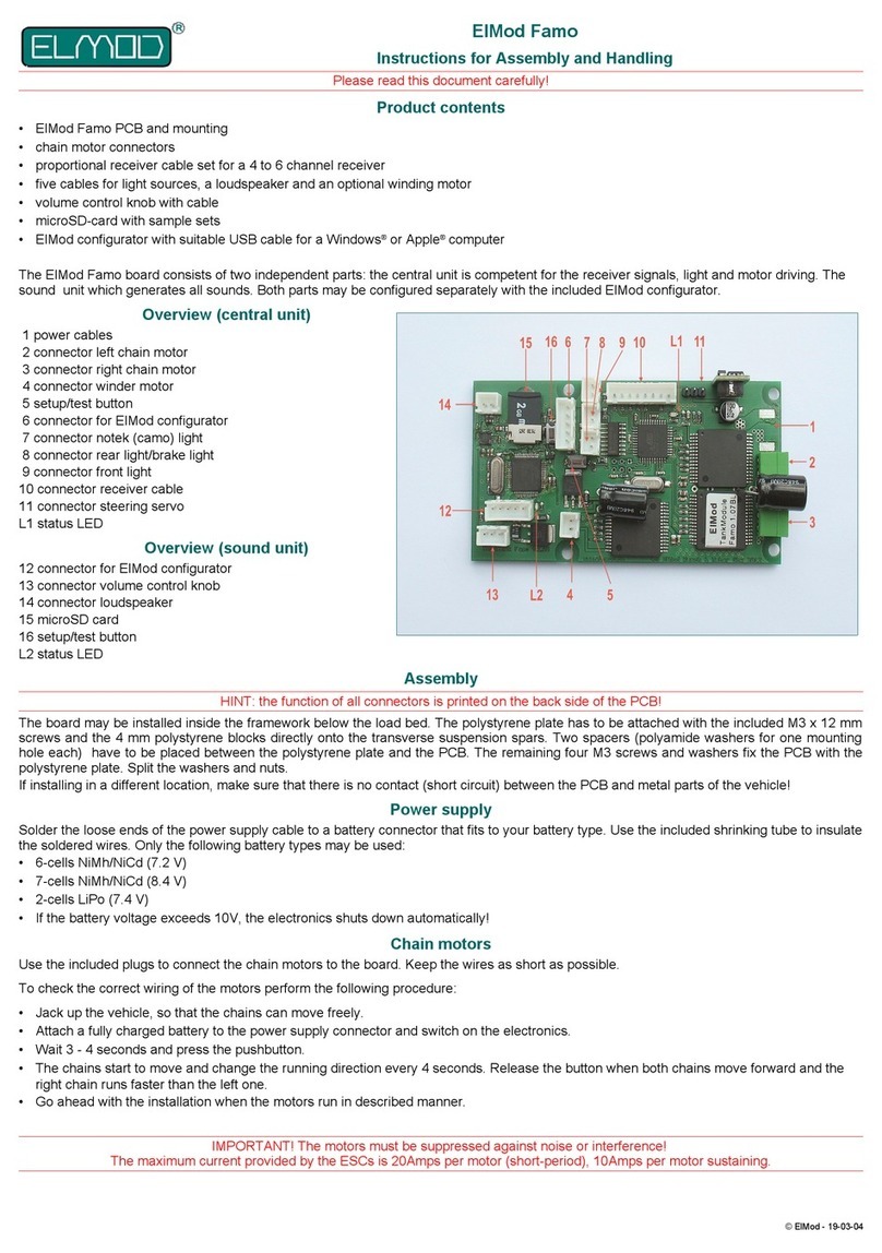
ElMod Famo Assembly instructions

ElMod

ElMod Famo Assembly instructions

Popular Control Unit manuals by other brands

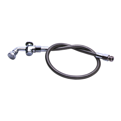
T&S B-16-K Installation and maintenance instructions

T&S

T&S B-16-K Installation and maintenance instructions

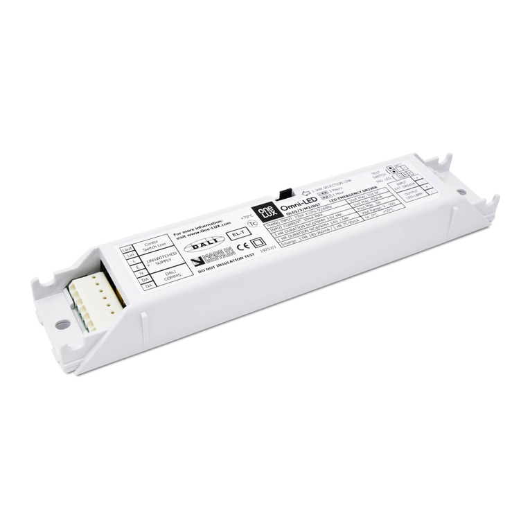
One Lux OMNI-LED DST OL12/2/M3/DST manual

One Lux

One Lux OMNI-LED DST OL12/2/M3/DST manual

National Instruments NI TB-4300B CALIBRATION PROCEDURE

National Instruments

National Instruments NI TB-4300B CALIBRATION PROCEDURE

CALEFFI 115 Series Installation and commissioning manual

CALEFFI

CALEFFI 115 Series Installation and commissioning manual

Mitsubishi Electric MELSEC iQ-RX40NC6B Application User's Manual

Mitsubishi Electric

Mitsubishi Electric MELSEC iQ-RX40NC6B Application User's Manual

BriskHeat ACR 3 MiniPRO Hot Bonder instruction manual

BriskHeat

BriskHeat ACR 3 MiniPRO Hot Bonder instruction manual

Leviton 110A00-1 Installation instructions and user guide

Leviton

Leviton 110A00-1 Installation instructions and user guide

Pixsys PLE500-6AD user manual

Pixsys

Pixsys PLE500-6AD user manual

Allmatic BIOS1 24V manual

Allmatic

Allmatic BIOS1 24V manual

Siemens SIRIUS 3RA2712 Equipment manual

Siemens

Siemens SIRIUS 3RA2712 Equipment manual

Cisco ATUC-4DMT-ISDN Installation and configuration

Cisco

Cisco ATUC-4DMT-ISDN Installation and configuration

Nice CLB207 Instructions and warnings for installation and use

Nice

Nice CLB207 Instructions and warnings for installation and use

DSC IT-100 installation instructions

DSC

DSC IT-100 installation instructions

BEKA BA3400 Series instructions

BEKA

BEKA BA3400 Series instructions

Vag GA INDUSTRIES 983-D Installation, operation and maintenance manual

Vag

Vag GA INDUSTRIES 983-D Installation, operation and maintenance manual

Freescale Semiconductor MC33696MOD Series Quick start user guide

Freescale Semiconductor

Freescale Semiconductor MC33696MOD Series Quick start user guide

cashco RANGER QCT Installation, operation & maintenance manual

cashco

cashco RANGER QCT Installation, operation & maintenance manual

Prins ValveCare user manual

Prins

Prins ValveCare user manual

manuals.online logo
manuals.online logoBrands
  • About & Mission
  • Contact us
  • Privacy Policy
  • Terms and Conditions

Copyright 2025 Manuals.Online. All Rights Reserved.