ElMod Famo Assembly instructions

ElMod Famo
Instructions for Assembly and Handling
Please read this document carefully!
Product contents
•ElMod Famo PCB and mounting
•chain motor connectors
•proportional receiver cable set for a 4 to 6 channel receiver
•five cables for light sources, a loudspea er and an optional winding motor
•volume control nob with cable
•microSD-card with sample sets
•ElMod configurator with suitable USB cable for a Windows® or Apple® computer
The ElMod Famo board consists of two independent parts: the central unit is competent for the receiver signals, light and motor driving. The
sound unit which generates all sounds. Both parts may be configured separately with the included ElMod configurator.
Overview (central unit)
1 power cables
2 connector left chain motor
3 connector right chain motor
4 connector winder motor
5 setup/test button
6 connector for ElMod configurator
7 connector note (camo) light
8 connector rear light/bra e light
9 connector front light
10 connector receiver cable
11 connector steering servo
L1 status LED
Overview (sound unit)
12 connector for ElMod configurator
13 connector volume control nob
14 connector loudspea er
15 microSD card
16 setup/test button
L2 status LED
Assembly
HINT: the function of all connectors is printed on the bac side of the PCB!
The board may be installed inside the framewor below the load bed. The polystyrene plate has to be attached with the included M3 x 12 mm
screws and the 4 mm polystyrene bloc s directly onto the transverse suspension spars. Two spacers (polyamide washers for one mounting
hole each) have to be placed between the polystyrene plate and the PCB. The remaining four M3 screws and washers fix the PCB with the
polystyrene plate. Split the washers and nuts.
If installing in a different location, ma e sure that there is no contact (short circuit) between the PCB and metal parts of the vehicle!
Power supply
Solder the loose ends of the power supply cable to a battery connector that fits to your battery type. Use the included shrin ing tube to insulate
the soldered wires. Only the following battery types may be used:
•6-cells NiMh/NiCd (7.2 V)
•7-cells NiMh/NiCd (8.4 V)
•2-cells LiPo (7.4 V)
•If the battery voltage exceeds 10V, the electronics shuts down automatically!
hain motors
Use the included plugs to connect the chain motors to the board. Keep the wires as short as possible.
To chec the correct wiring of the motors perform the following procedure:
•Jac up the vehicle, so that the chains can move freely.
•Attach a fully charged battery to the power supply connector and switch on the electronics.
•Wait 3 - 4 seconds and press the pushbutton.
•The chains start to move and change the running direction every 4 seconds. Release the button when both chains move forward and the
right chain runs faster than the left one.
•Go ahead with the installation when the motors run in described manner.
IMPORTANT! The motors must be suppressed against noise or interference!
The maximum current provided by the ESCs is 20Amps per motor (short-period), 10Amps per motor sustaining.
© ElMod - 19-03-04

Steering servo
Attach a proper steering servo to the connector 11. The ground wire shows towards the right edge of the board. It must be ensured, that the
steering servo doesn't exceed the maximum current of 1.5Amps.
Winder motor
IMPORTANT! The motors must be suppressed against noise or interference!
Solder the provided 2-wire cable to your winder motor and attach the cable to the connector 4. The motor current may not exceed 10Amps.
Light
All light connectors are equipped with a dropping resistor. It protects the light sources from overcurrent (20-50mA) and the board from
shortcuts. LEDs may be connected directly to the output. All light outputs are able to drive one or two LEDs. The brightness of each light
source may be configured individually with the ElMod configurator.
•Front light: connect one or two white LEDs parallely to the connector 9.
•Combined rear light/bra e light: attach one or two red LED serially to the connector 8.
•Note : use the connector 7 for the note blac out light.
Status LED (central unit)
The status LED L1 shows the condition of the central unit
on Tan Module is in operational state
Single short out Stic movement detected
Fast blin ing No valid signal from receiver*
Slow blin ing Faulty communication with the sound unit
Double blin ing Faulty CPU power supply**
Single triple blin ing Bootloader activated. The module is ready for firmware update.
*no connection to the sender is established or the transmission path between sender and receiver is disturbed. Please chec the wiring and the proper function
of the RC radio and receiver. If necessary chec the operability of the RC equipment with a servo.
**undervoltage on the CPU detected. Switch off the power for 10 seconds. If the error remains, assure that the ElMod configurator USB dongle is disconnected
and retry.
R receiver
The Famo module may be used with four, five or six channel receiver. The currently active mode of operation is recognized automatically.
Please consider that the radio must be setup correctly (all mixers must be deactivated, the servo deflection must be 100% and the trimming
has to be centered)
If the channels five and/or six are used, they must be equipped either with a slider, nob or a 3-way-switch (up-off-down). Otherwise only four-
channel operation is possible (no user sounds are available). For proper function the wires of unused channels may not be connected to the
receiver.
The Famo module provides the power supply for the receiver (BEC, stabilized 5V DC) via the red/blac wires which are part of the included
proportional cable set.
The receiver cable has to be attached to the receiver connector on the Famo module. The wire colors are:
hannel ontrol Function
1Right stic Acceleration
2Steering
3Left stic Light and ignition
4Winder motor (optional)
Depending on the receiver it may be necessary to adjust the channel order or swap its movement direction.
Chec the manual of your RC gear for details.
Special functions and light control ( hannels 3 and 4)
Left stick (channel 3+4)
Motor ignition
Note (camo light) on/off (half deflection)
Front light on/off (full deflection)
Optional wider motor
User defined sounds
Up to 8 user sounds may be defined and up to four user sounds may be controlled by each channel.
hannel ontrol Function
53-way switch User sound 1 (hold for 3 sec. and release for user sound 5)
User sound 2 (hold for 3 sec. and release for user sound 6)
63-way switch User sound 3 (hold for 3 sec. and release for user sound 7)
User sound 4 (hold for 3 sec. and release for user sound 8)
The playbac may be stopped by moving the switch in the opposite direction.
Undervoltage protection
The Tan Module features an under voltage protection to protect the batteries from deep discharge. On delivery the threshold voltage is set to
6 volts for 7.2V NiMh/NiCd batteries. If the voltage drops below 6 volts, the vehicle stops and the attached lights start blin ing. In this case
replace or recharge the battery.
© ElMod - 19-03-04

Overvoltage protection
If a voltage of 10V or higher is detected, the electronics shut down and the attached lights start blin ing.
Sound unit
•Connect the volume control nob to the connector 13.
•Solder a suitable 8 Ohms spea er to the included spea er cable. Plug the cable to the connector 14. The polarity (+/-) is ali e.
Status LED (sound unit)
The status LED L2 shows the condition of the sound unit
on Blaster is operational
blin ing Blaster cannot establish connection to the central unit
off SD card missing or faulty
flic ering a sound is being played
blin s exactly 3 times Bootloader active and the sound unit is ready for firmware update
First run
•Ma e sure all cables have been installed as described above.
•Ma e sure that the SD card is well fixed.
•Install a full charged battery and switch on the vehicle.
•The status LEDs L1 and L2 must be on. L1 may blin for a couple of seconds until the central unit is synced with the receiver.
•For a function test, press the pushbutton 16. A sound will be played every few seconds. If you cannot hear anything, adjust the volume with
the volume control nob.
•use the included ElMod Configurator with your Windows® or Apple® computer to fine tune the module's settings.
Motor ignition
If the power is switched on, the main engine will be off by default. Move and release the left stic (channel 3) to the upper most position to
ignite the motor. Move the stic up again to switch the motor off.
Setting up a sample set
The provided microSD card includes several ready-to-use sample sets. For activation of a particular sample set, insert the card in a suitable
card reader of your personal computer and start the program “MasterBlaster.exe” which is located in the root directory of the SD card.
The microSD card includes several third-party sample sets. We are not liable for the quality or the content of these sample sets!
onfiguration and update of the central unit
The ElMod configurator allows a very detailed configuration and setup of the central unit of the Famo module. To run the configuration
download and install the ElMod configurator software from our web site, attach the USB cable to the connector 6 and power up the module.
If a new firmware version for the Famo module is released, you will be able to upload it via the ElMod configurator. To activate the update
process download and install the current version of the ElMod configurator Software, attach the USB cable to the connector 6, press and hold
the pushbutton 5 and switch on the power. The LED L1 blin s exactly 3 times. Follow the directions shown by the ElMod configurator software.
onfiguration and update of the sound unit
The ElMod configurator allows a very detailed configuration and setup of the sound unit. To run the configuration download and install the
ElMod configurator Software from our web site, attach the USB cable to the connector 12 and power up the module.
If a new firmware version for the Famo module is released, you will be able to upload it via the ElMod configurator. To activate the update
process download and install the current version of the ElMod configurator Software, attach the USB cable to the connector 12, press and hold
the pushbutton 16 and switch on the power. The LED L2 blin s exactly 3 times. Follow the directions shown by the ElMod configurator
software.
© ElMod - 19-03-04

Dimensions
Dimensions of the P B and the polystyrene mounting plate
Nicht geeignet für Kinder unter 14 Jahren. Not suitable for hildren under 14 years.
Ne convient pas pour des enfants de moins de 14 ans. Niet geschikt voor kinderen onder de 14 jaar.
ElMod Thomas Kusch
Seebuc weg 9
D-78054 Villingen-Schwenningen, Germany
ElMod Thomas Kusch
[email protected] http://www.elmod.eu
© ElMod - 19-03-04
2 mm
67.80
46.00
48.60
102.00
54.00
Table of contents
Other ElMod Control Unit manuals

ElMod
ElMod Fusion ECO Operating and maintenance manual
ElMod
ElMod ThinkTank Tank Module ECO Flex Assembly instructions
ElMod
ElMod Fusion ECO Operating and maintenance manual
ElMod
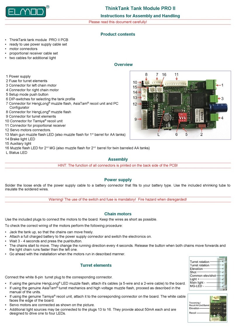
ElMod ThinkTank Tank Module PRO II Assembly instructions
ElMod
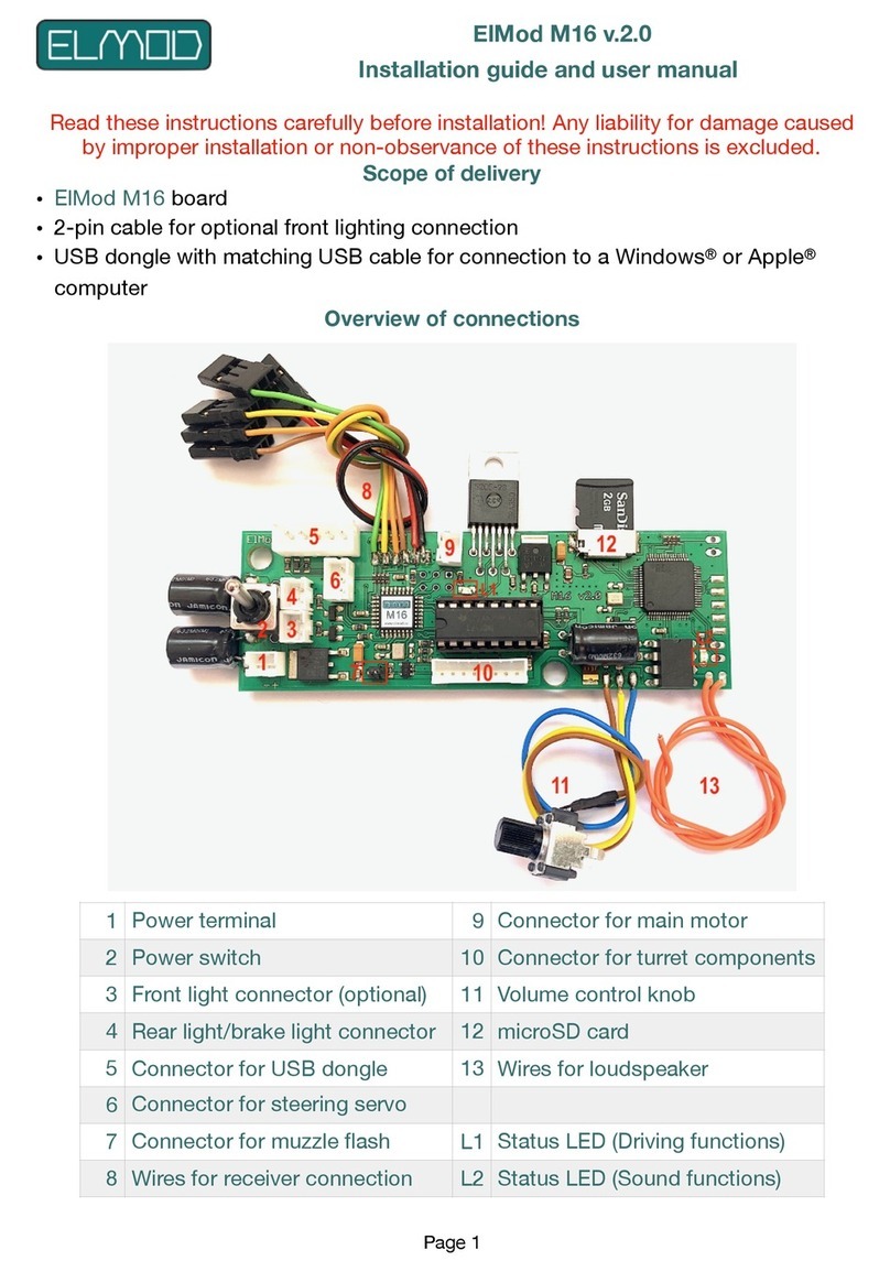
ElMod M16 v.2.0 Assembly instructions
ElMod
ElMod ThinkTank Tank Module PRO II Flex Assembly instructions
ElMod
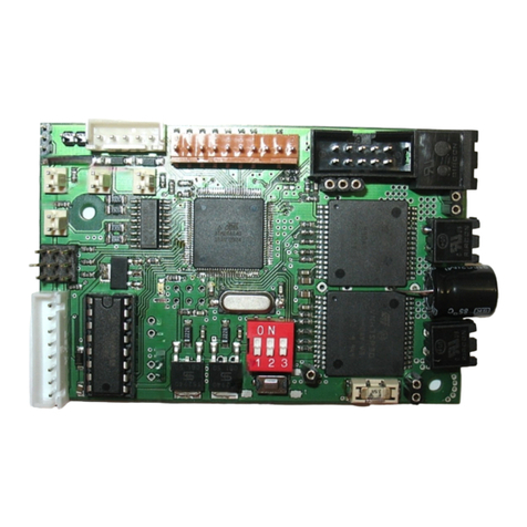
ElMod ThinkTank Pro Assembly instructions
ElMod
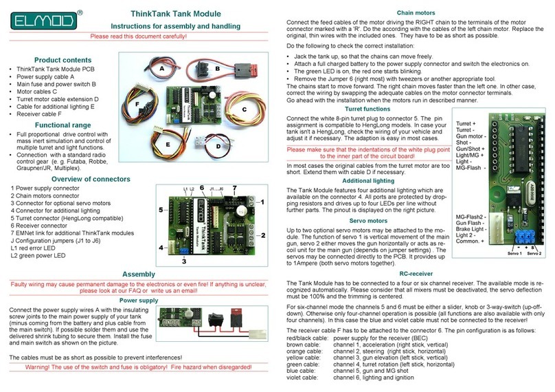
ElMod ThinkTank Tank Module Assembly instructions

ElMod
ElMod ThinkTank Tank Module ECO Assembly instructions
ElMod
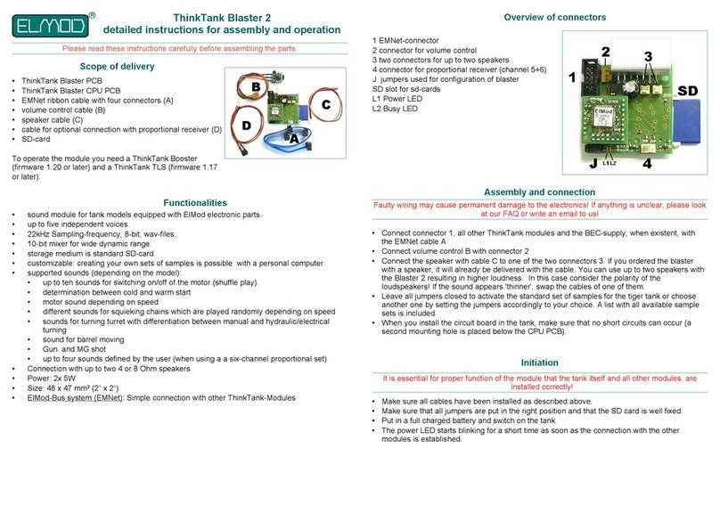
ElMod ThinkTank Blaster 2 Installation instructions
